Mold slider
Injection Mold Slider Design: Structure, Function, and Best Practices
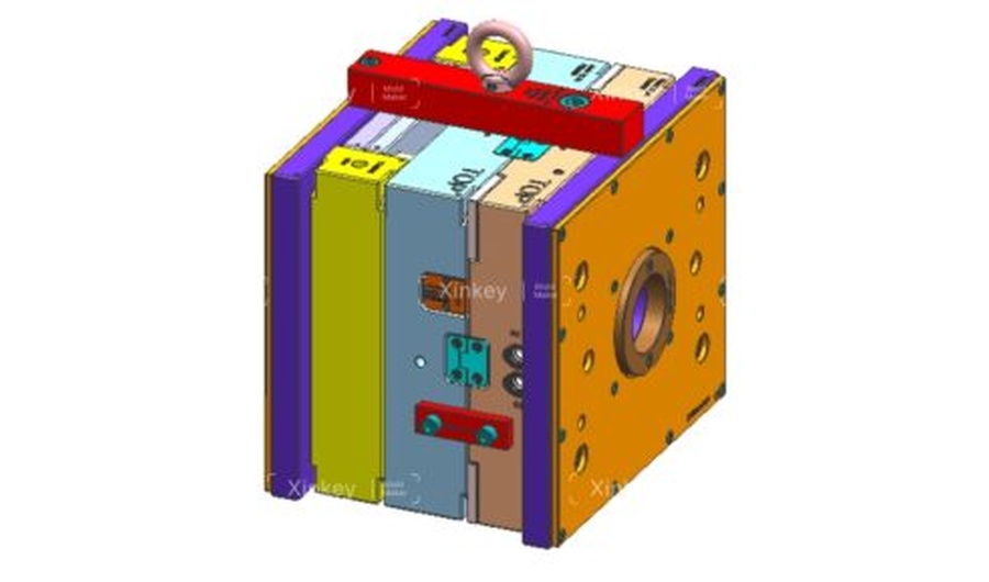
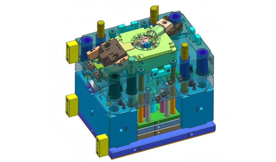
Introduction Sliders (also called side actions or side cores) are mold components that move perpendicular—or at an angle—to the mold opening direction. They are used to form and release external undercuts that would otherwise prevent straight ejection. For mold engineers working on complex plastic parts, understanding slider design is essential. What Is a Mold Slider? A slider is a movable mold component that travels sideways during the opening stroke to release external undercuts on a molded part. It is typically driven by an angle pin (also called a cam pin or horn pin) mounted on the stationary half of the mold. As the mold opens, the angle pin pushes the slider outward. During mold closing, the slider is guided back into its working position, ready for the next cycle. To ensure stability during injection, the slider is locked in place by a heel block (locking wedge). Without this support, high cavity pressure—often reaching hundreds of tons—can force the slider out of position, leading to flash or dimensional variation. For standard mold construction, pre-hardened tool steels such as P20 are commonly used for the slider body. In higher-volume applications, however, P20 alone is not sufficient. Hardened inserts or wear plates are often added in high-contact zones to reduce friction, improve wear resistance, and significantly extend tool life. The slider is guided by gibs or guide pillars to maintain alignment throughout its travel. The travel distance must be at least equal to the undercut depth plus a safety margin of 2–3 mm. Why Sliders Are Necessary Many plastic parts include features such as side holes, threads, hooks, clips, or recessed geometries on external surfaces. These features create undercuts that prevent straight-line ejection from the mold. Without a side-action system like a slider, the part would become mechanically locked in the cavity. Any attempt to eject it directly would risk part damage, mold wear, or even production stoppage. In practice, the slider acts as a required release mechanism—it must fully retract before the ejection system activates. If timing is incorrect, the part can remain trapped, leading to potential damage and unplanned downtime. Compared to internal lifters, sliders are generally more robust for external undercuts. They are driven by the mold opening motion and mechanically locked against injection pressure by the heel block, making them suitable for high-volume production environments where millions of cycles are required. A key advantage of sliders is their load distribution capability. The heel block and guide surfaces spread injection forces over a larger contact area, reducing deflection and wear compared to smaller mechanical lifting systems. Common Slider Problems 1. Galling and SeizureSlider galling occurs when sliding surfaces operate with insufficient lubrication, leading to metal pickup and eventual seizure. This is especially common in molds running abrasive materials such as glass-filled nylon or mineral-filled polypropylene. Once galling begins, it tends to accelerate quickly and can ultimately cause slider lock-up and mold disassembly for repair. 2. Excessive Angle Pin LoadWhen the angle pin exceeds approximately 25°, side loading increases significantly. This accelerates wear on gibs, heel blocks, and the angle pin itself. Steeper angles also increase the force required during mold opening, placing additional stress on the entire mechanism over time. 3. Flash on Shut-Off SurfacesFlash on the slider shut-off face indicates improper seating. Common causes include worn heel blocks, insufficient preload, or slight angle pin deformation. If not addressed early, flash buildup can accelerate wear on both the slider and mating surfaces. 4. Timing MisalignmentIncorrect slider timing can cause serious defects. If the slider moves before the part has fully released, it may drag the part laterally, resulting in surface scuffs, deformation, or dimensional distortion. Design Solutions and Best Practices Maintain angle pin geometry between 15° and 22° to balance force and reduce side loading. Machine dedicated lubrication grooves into wear plates, and ensure grease reaches all sliding interfaces. Use self-lubricating materials such as AMPCO bronze, Oilite bushings, or composite wear inserts. Implement a spring-loaded return system to guarantee full slider seating before mold closure. Design heel block locking angles 2–3° steeper than the angle pin to ensure secure shut-off under pressure. Add an early ejector return system so ejector pins retract before slider movement to avoid mechanical interference. Pro Tip A well-designed slider should feel like a precision mechanism—smooth in motion, positive in locking, and consistent from the first shot to the last. Good performance is rarely about complexity. It comes from fundamentals: selecting the right wear materials, ensuring proper lubrication delivery, and designing a reliable mechanical return system. When these basics are correct, the mold runs with minimal intervention. However, the most cost-effective slider is often the one you never build. Always evaluate whether a small part design change can eliminate the undercut entirely. Simplifying the geometry usually leads to lower cost, higher reliability, and easier maintenance.
READ MORE
Mold Cycle Time
Mold Cycle Time: The Hidden Profit Lever in Injection Molding
If you’ve spent any time around an injection molding shop floor, you’ll notice one thing pretty quickly: everyone talks about quality, but the real game is time. Cycle time isn’t just a number on the machine screen—it’s directly tied to cost, output, and ultimately, your profit margin. In many projects, cycle time doesn’t get much attention early on. By the time it becomes a concern, the mold design is already fixed and changes are costly. In this article, we’ll walk through what cycle time actually means on the shop floor, what tends to slow it down, and where you can realistically make improvements—without risking part quality. What Is Mold Cycle Time? Mold cycle time refers to the total time required to complete one full injection molding process cycle. That includes: Mold closing Injection (filling) Packing and holding Cooling Mold opening Part ejection In simple terms:Cycle time is basically the time it takes from one mold close to the next shot. At a glance, 25 seconds versus 30 seconds doesn’t raise alarms. But in continuous production, it adds up quickly. Over time, you end up with fewer cycles, which directly means less output from the same resources. That’s where cycle time starts to matter—not on paper, but on your bottom line. Machine cost per part goes up Labor and energy costs increase Delivery timelines stretch That’s why experienced mold designers don’t just design for “good parts”—they design for efficient cycles. Key Factors That Affect Mold Cycle Time Cycle time isn’t controlled by a single parameter. It’s the result of multiple design and process decisions. 1. Cooling Time (The Biggest Factor) Cooling often takes up 60–80% of the total cycle time. What influences it: Part thickness Material type Mold temperature Cooling channel design Thicker parts hold heat longer. Poor cooling layout makes it worse. 👉 If you want faster cycles, start with better cooling—not faster injection. 2. Part Design Design decisions made early on can lock in your cycle time. Key design impacts: Uniform wall thickness → faster cooling Avoiding thick ribs/bosses → less heat concentration Proper draft angles → faster ejection Bad design = longer cooling + ejection problems. 3. Material Selection Different plastics behave differently. For example: PP / PE → faster cooling PC / ABS → slower cooling Glass-filled materials → require more control Choosing material without considering cycle time is a common mistake. 4. Mold Design & Engineering A well-built mold can dramatically reduce cycle time. Critical elements: Optimized cooling channels (conformal cooling if possible) Proper gate location Efficient venting Balanced runner system An average mold “works.”A well-engineered mold prints money faster. 5. Machine Parameters Even with a perfect mold, poor machine settings can slow everything down. Key parameters: Injection speed Holding pressure/time Cooling time setting Clamp open/close speed Fine-tuning matters—but it cannot fix bad design. Practical Ways to Reduce Mold Cycle Time Here’s what actually works in real production environments: Optimize Cooling System First Add cooling channels near hot spots Use baffles or bubblers if needed Consider conformal cooling for complex parts 👉 This gives the biggest ROI. Reduce Wall Thickness (When Possible) Even a small reduction can significantly cut cooling time. Example:3.0 mm → 2.5 mm can reduce cooling time noticeably But always balance strength and function. Improve Mold Venting Better venting allows: Faster filling Reduced burn marks Lower injection pressure Which indirectly shortens cycle time. Use High-Efficiency Mold Materials Beryllium copper inserts (for hot areas) High thermal conductivity steels These help remove heat faster. Automate Where Possible Robotic part removal Faster, consistent ejection Manual handling slows cycles more than people realize. Common Mistakes That Increase Cycle Time Let’s be honest—these happen all the time: Overdesigning wall thickness “just to be safe” Ignoring cooling during mold design Poor gate placement leading to uneven filling Setting excessive cooling time as a safety buffer Trying to fix design problems with machine parameters These decisions quietly eat into your margins. Cycle Time vs. Part Quality: Finding the Balance Reducing cycle time too aggressively can backfire. You may see: Warpage Sink marks Internal stress Dimensional instability The goal is not the shortest cycle—it’s the optimal cycle. Final Thoughts Mold cycle time is one of the most underestimated factors in injection molding profitability. It’s not just a processing parameter—it’s the result of: Smart part design Thoughtful mold engineering Proper material selection Controlled processing If you think about cycle time early—while the part and mold are still being designed—you give yourself much more room to optimize. Once the tooling is finished, improving it becomes a lot harder and more expensive. FAQ Q: What is a “good” cycle time in injection molding?A: There isn’t a single benchmark. It depends on the part—its size, geometry, and material. Simple, thin-wall parts can run quite fast, often under 20 seconds. Larger or thicker parts usually need more time, sometimes 40 seconds or more. Q: What affects cooling time the most?A: Most of the time, it’s the wall thickness and the cooling layout inside the mold. Thicker areas take longer to release heat, and if the cooling channels aren’t placed well, the delay becomes even more obvious. Q: Why is my cycle time too long?A: Common causes include thick parts, poor cooling design, conservative machine settings, or inefficient mold layout.
READ MORE
Mold lifter
Why Internal Undercuts Are a Serious Problem in Injection Molding
Let’s be honest: internal undercuts are a nightmare for mold designers. Unlike external features, they can’t be handled with standard sliders. If the geometry isn’t designed correctly, the consequences are serious: Parts stuck permanently on the core Surface damage or scuffing Lifter rod breakage Costly production downtime When dealing with internal clips or bosses, the mold lifter becomes the most reliable mechanical solution. How a Mold Lifter Works: The “Side-Step” Principle A mold lifter doesn’t move like a traditional slider. Instead, it is driven by the ejector system. During the ejection cycle: The lifter moves upward with the ejector plate At the same time, it follows an angled path This creates a combined vertical + lateral motion This lateral movement—often called the “side-step”—is what releases the undercut. Key Design Rule Always allow at least 2 mm of extra travel beyond the undercut depth. Anything less increases the risk of: Drag marks Surface scratches Incomplete release The Most Common Mistake: Incorrect Lifter Angle One of the biggest design errors is pushing the lifter angle too steep to save space. Recommended Lifter Angle Optimal range: 5° – 11° Risk Zone Above 15°: High risk of binding and failure At steeper angles: Lateral force increases significantly Vertical motion becomes restricted The lifter may jam or the rod may buckle When Steep Angles Are Unavoidable If your design forces a larger angle, consider: Hinged lifter base T-slot lifter design These help reduce stress on the lifter rod and improve durability. Material Selection: Prevent Galling and Wear Lifter systems operate under: High pressure High temperature Continuous metal-to-metal contact Choosing the wrong material can lead to galling, where surfaces weld together and fail. Recommended Materials H13 tool steel 718H pre-hardened steel Hardness Guideline Target: 50–54 HRC Keep the lifter slightly harder than the core High-Performance Option For faster cycle times: Use Beryllium Copper inserts Benefits: Faster heat dissipation Reduced cooling time Increased production efficiency 3 Expert Tips for a Bulletproof Lifter Design 1. Add a “Tail” Guide Always support the bottom of the lifter rod with a guide block. Without support: The rod vibrates Vibration leads to flash and wear 2. Use Oil Grooves Friction is the enemy of any moving component. Best practice: Add lubrication grooves to sliding surfaces Exception: Medical molds → use DLC coating instead of oil 3. Control the Parting Line (PL) Fit The lifter shut-off surface must match the core perfectly. Even a 0.01 mm gap can cause: Visible witness lines Poor surface quality Lifter vs Slider: Which One Should You Use? Choosing between a lifter and a slider depends entirely on undercut location. Use a Slider When: The undercut is external There is enough space for side action Use a Lifter When: The undercut is internal Space is limited Hydraulic systems are not practical Final Thoughts A mold lifter is one of the most efficient solutions for internal undercuts—but only when designed correctly. By controlling: Angle Travel clearance Material selection Structural support You can turn a high-risk feature into a reliable, repeatable mechanism that keeps your production line running smoothly. Need help optimizing your mold design or solving complex undercuts?Visit www.xinkeymould.com to get expert support and improve your tooling performance.
READ MORE
PARTING LINE
The Parting Line: Where Your Mold Design Meets Reality
Ever run your thumb along a new plastic part and felt that sharp, ugly ridge digging into your skin? That’s the parting line. It’s supposed to be a seamless transition—but more often than not, it becomes the scar of a rushed design. On a 2D CAD screen, the parting line looks like a simple intersection. But on the shop floor, it’s a high-stakes battlefield—where the core and cavity meet. If these two halves don’t “kiss” perfectly, your part is compromised before it even leaves the press. Why the Parting Line Matters A poorly designed parting line isn’t just an eyesore—it’s a profit killer: ❌ Manual de-flashing costs ❌ Higher scrap rates ❌ Repeated DFM revisions ❌ Tool wear and maintenance 1. Stop Calling It a “Line” — It’s a Strategic Split Think of the parting line as the mechanical equator of your part. It determines whether your part can be released from the mold—or gets trapped inside it. Common Pitfalls 🔴 The “Trapped” Nightmare (Undercuts)Misplace the parting line by even 1 mm, and you create an undercut.Now your simple mold suddenly requires: Slides Lifters Complex mechanisms ➡️ Result: Tooling cost can double instantly 🔴 The “Kiss-Off” Surface ProblemThe parting line isn’t just a boundary—it’s a high-pressure seal. Complex geometries like: Zig-zags Sharp transitions Steep curves …lead to faster wear and sealing failure. ✅ Golden Rule Keep it flat. Keep it simple. Flat parting lines = easier machining Better sealing performance Longer tool life 2. The Messy Reality of Flash (And Why It’s Bleeding Your Profits) If your parts have a thin, unwanted fringe around the edges—you’re dealing with flash. In the shop, we call it “bleeding.” Why Flash Happens During injection, molten plastic is under extreme pressure and will escape through any gap. 🔧 Root Causes: • Steel Fatigue Shut-off surfaces wear down over time Edges round off after high cycle counts • Poor Alignment Core and cavity not perfectly matched Even microscopic gaps cause flash • The “Tonnage Trap”Increasing clamp force won’t fix bad design. More tonnage = more damage (vent crushing, plate deformation) ⚠️ Reality Check (New Molds) If you see flash during the first T1 trial: 👉 It’s NOT a machine issue👉 It’s a tooling problem Fix the shut-off alignment, not the press settings. 3. How to Hide the Parting Line (Designer’s Secret) The best parting line is the one no one notices. High-end brands like Apple or Dyson obsess over this detail—and you should too. Pro Techniques ✔ Follow the EdgePlace the parting line along sharp edges or corners. ✔ Use the “Step” MethodHide it inside: Grooves Decorative lines Design breaks ✔ Texture Contrast One side matte One side glossy ➡️ Turns a flaw into a design feature 4. Why Draft Angle Is Your Best Friend You can’t design a proper parting line without draft angle. Every wall must taper away from the mold. Without Draft Parts scrape during ejection Surface damage (drag marks) Galling (white scratches) ✅ Recommended Draft Angles Smooth surfaces: ≥ 0.5° Textured surfaces: ≥ 3° More draft = easier ejection + better surface finish 5. The Bottom Line: Consult Early One of the biggest mistakes designers make: Finishing the design… then “throwing it over the wall” to the mold maker. ✅ Best Practice Engage your mold maker early and ask: Where will the parting line be? Will the shut-off surfaces wear quickly? Can we move the line to a hidden area? Final Takeaway A few hours of DFM discussion today can save: Weeks of rework Thousands in scrap Endless frustration on the shop floor In Short The parting line isn’t just a line—it’s where design meets manufacturing reality.
READ MORE
mold core and cavity
Why Your Mold Core & Cavity Design is Probably Making Your Molder Grumpy
Why Your Mold Core & Cavity Design is Probably Making Your Molder Grumpy It’s Not Just “Tooling” — It’s Controlled Violence Let’s be real. In the injection molding world, we love to simplify things by calling it “the mold.” But step onto any busy shop floor—stand next to a humming 300-ton press—and you’ll quickly realize something: This isn’t just tooling.It’s a high-precision, high-force collision between two massive blocks of steel. And when the Core and Cavity fall out of sync—even slightly—you’ll pay for it immediately: Flashing Parts sticking in the wrong side Scrap piling up Cycle time going nowhere Let’s drop the textbook explanation and talk about how this actually works in the real world. A-Side vs B-Side: The Reality Behind the Names The Cavity (A-Side) — The “Showroom” The cavity is the part everyone sees—and judges. Stationary side of the mold Typically connected to the hot runner system Responsible for surface finish and appearance If your product needs: Mirror polish Texture (VDI, MT, etc.) Cosmetic perfection 👉 It all happens here. The Core (B-Side) — The Workhorse Now let’s talk about the side that actually does the heavy lifting. Moving side of the mold Houses ejector pins Forms internal features: Ribs Bosses / standoffs Clips and functional geometry This is where things get mechanical—and unforgiving. The Real Problem: Plastic Shrinkage = Core Death Grip Here’s what keeps molders up at night. The moment molten plastic hits steel, it starts to shrink.But it doesn’t shrink evenly—it grips the core. Think of it like this: The plastic is trying to “lock itself” onto every rib, pin, and detail on the B-side. If your design doesn’t account for that: Parts won’t eject Parts stick randomly Operators step in manually Cycle time collapses And yes—sometimes the part stays in the Cavity instead of the Core, which is even worse. Common Shop Floor Headaches (And How to Fix Them) 1. Draft — The Most Ignored Lifesaver No draft = no release. Simple as that. 0° draft → scuff marks, drag, sticking ≥ 1° draft → smoother release 👉 Draft isn’t optional. It’s survival. 2. The Vacuum Effect Sometimes your cavity is too perfect. A super smooth surface can create a vacuum seal that holds the part in place. Solutions: Add micro venting Use air poppets Break the seal intentionally 3. Texture Strategy (Not Just Aesthetics) Smart mold design uses texture as a tool—not decoration. Cavity → smoother (for appearance) Core → slightly rougher Why? 👉 You want the part to stick to the B-sideSo the ejector system can actually do its job. Cooling: The Silent Profit Killer Most people think cooling = drilling holes. That’s wrong. The Reality: The Core is almost always the hottest zone: Surrounded by molten plastic Poor airflow Heat gets trapped easily If cooling is poorly designed: Parts warp Dimensions drift Post-ejection deformation happens Looks fine out of the mold… turns into a potato chip 10 minutes later. Better Solutions: Bubblers Beryllium copper inserts Conformal cooling (if budget allows) Steel Selection: Where Cheap Becomes Expensive We get it—materials like S136 or NAK80 aren’t cheap. But cutting cost here is a long-term mistake. Cavity (A-Side): Needs hardness Maintains surface finish Recommended: S136 / NAK80 Core (B-Side): Needs toughness Handles mechanical stress + ejection cycles Can tolerate slightly softer but durable steels 👉 Using P20 for a high-volume, high-finish cavity?That’s not saving money—that’s delaying failure. The Takeaway Core and Cavity aren’t just components. They are a balance of physics, heat, friction, and timing. If you’re currently in the DFM stage, don’t just review the 3D model. Ask yourself: Where will the plastic shrink—and grip? Where will heat accumulate? How will this part actually release from steel? Because in real production:Good design = stable productionBad design = daily firefighting Need a Second Pair of Eyes? We’ve spent years on the shop floor solving exactly these problems—hands-on, not theoretical. If you want your tool to run clean from shot #1: 👉 Reach out to us. Let’s make sure your mold works in reality, not just on screen.
READ MORE
Mold Runner
Beyond the Part: Why the “Mold Runner” is the Secret to Your Profit Margin
It’s easy to get tunnel vision on the final product—obsessing over tolerances, surface finish, and resin types. But on the shop floor, the real deal-breaker lies in that “no-man’s land” between the nozzle and the cavity. If your runner system isn’t properly engineered, a promising project can quickly shift from a profit-maker to a costly headache. We’re talking about the mold runner system. Think of the runner as the circulatory system of your mold. When the flow is restricted or inefficient, the entire process suffers. In this guide, we break down how runner systems work—and why choosing between cold and hot runners is more than just a budget decision. 1. The Cold Runner: The Reliable Workhorse Cold runner systems are the traditional and widely used option in injection molding. After the plastic is injected, the material in the runner cools and solidifies along with the part. When the mold opens, the runner is ejected as scrap (commonly referred to as regrind). Advantages Lower tooling cost Simple design and easy maintenance Ideal for frequent material or color changes Suitable for abrasive or filled materials Limitations Material waste in every cycle Regrind may reduce mechanical properties Longer cycle times due to runner cooling Increased cost over time for high-volume production While regrinding is possible, it often comes at the expense of part performance and process consistency. 2. The Hot Runner: The High-Speed Specialist A hot runner system keeps the plastic in a molten state inside a heated manifold. Unlike cold runners, the material does not solidify and is not ejected with the part. Advantages Zero material waste (no runners, no scrap) Faster cycle times Improved efficiency in high-volume production Better part consistency Considerations Higher upfront tooling investment Requires precise temperature control More complex maintenance Downtime risk if components (heaters, thermocouples) fail For large-scale production—especially in the millions of parts—a hot runner system often pays for itself through material savings and cycle time reduction. 3. Engineering a Better Flow: Key Design Principles Regardless of the system you choose, runner design plays a critical role in performance. Here are three essential principles from real-world production experience: Balance is Everything In multi-cavity molds, the runner must be balanced so that molten plastic reaches each cavity simultaneously. Even small variations in length or diameter can cause: Short shots in some cavities Flash in others A well-balanced runner ensures uniform filling and consistent part quality. The Rounder, The Better A full-round runner cross-section is the industry gold standard. Why? Lower surface-to-volume ratio Reduced heat loss Less flow resistance While half-round runners may reduce machining cost, they often lead to higher pressure loss and reduced efficiency. Don’t Forget the Cold Slug Well For cold runner systems, always include a cold slug well at the end of the sprue. Its purpose: Capture the initial “cold” plastic from the nozzle Prevent defects and weak points in the final part This small design detail can significantly improve part integrity. 4. Which One Should You Choose? Choosing between cold and hot runners depends on your production goals. Consider these three key factors: Production Volume Under 50,000 parts → Cold runner is typically more cost-effective Over 200,000 parts → Hot runner becomes a strong investment Material Cost Low-cost materials → Cold runner is acceptable High-performance or expensive resins → Hot runner minimizes waste and saves cost Cycle Time Sensitivity If machine time is critical and billed per second,a hot runner system can significantly reduce overall production cost through faster cycles. The Bottom Line A mold runner is not just a pathway for molten plastic—it is a critical factor in both part quality and profitability. Cold runners offer simplicity and lower upfront costs Hot runners deliver efficiency, speed, and long-term savings The right choice depends on your specific production needs—but in every case, thoughtful runner design is essential. Before starting your next tooling project, take a closer look at the runner system. It may be the most important hidden factor shaping your manufacturing success.
READ MORE
Products
Contacts
WhatsApp
Email