cooling-design
The Engine of the Cycle: A No-Nonsense Guide to Mold Cooling Design
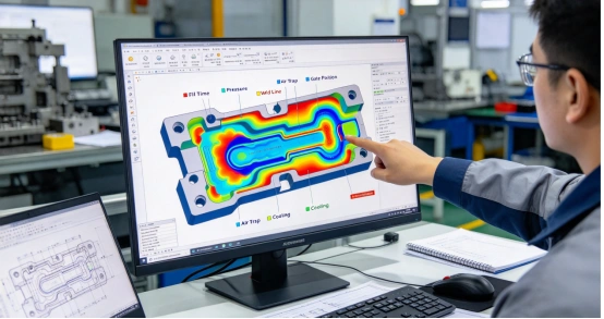
Introduction Let’s be real: cooling isn’t just a “phase” of the injection molding cycle; it is the cycle. It usually eats up 60% to 80% of your total time on the press. If your cooling system is an afterthought, you’re essentially leaving money on the table every time the mold opens. A well-engineered system is the difference between a high-speed production run and a “scrap-making machine” that produces warped, inconsistent parts. Why Cooling is the “Heartbeat” of the Tool Molds need to breathe—plain and simple. You’re forcing 250°C liquid into a tool and expecting it to become a rock-solid part almost instantly. But if that cooling isn’t perfectly balanced, you’re in for a headache. One side freezes, the other pulls, and suddenly your precision part is curling like a potato chip. If you’re chasing dimensional stability, you can’t just ‘hope’ for even cooling; you have to engineer it into the foundation of the tool. Every second you shave off that cooling cycle by optimizing your “hot spots” is a direct injection of profit into the life of the mold. Layout Strategy: Don’t Just Drill Holes The goal is simple but tricky: get the water as close to the cavity as you dare without compromising the structural integrity of the steel. The “Golden Rule” We generally try to keep the center of the cooling lines about 1.5 to 2 diameters away from the cavity surface. Too far, and the heat lingers; too close, and you risk a catastrophic “blowout” under the pressure of the injection. Contouring is King For flat panels, a basic grid works fine. But for complex 3D shapes, your cooling lines need to mimic the part’s geometry. If the part is complex, don’t be afraid to look at Conformal Cooling (3D printed inserts). Look, the upfront cost for conformal cooling is steeper, but it’s the only real way to kill those ‘unsolvable’ hot spots that a traditional drill bit just can’t touch. It’s about eliminating the bottleneck before it eats your profit. The Speed of the Flow Don’t just turn on the water and assume the tool is cooling. It’s not just about flow; it’s about turbulence. You need to hit a Reynolds number over 4,000 to actually scrub the heat off the steel. If that coolant is just ‘lazy-rivering’ through the lines, it’s not doing its job—you’re basically just circulating lukewarm water while your cycle time suffers. Getting into the “Dead Zones” Deep cores and tight pockets are a cooling nightmare because you can’t just drill a straight hole into them. You’ve got to get creative with your plumbing: Bubblers For those deep, skinny cores where a standard drill bit is useless, we rely on Bubblers. You’re basically sticking a tube up a blind hole to spray water directly at the ‘hot spot’ at the very tip. The coolant hits the top and tumbles back down around the outside of the tube. It’s the only real way to stop those narrow features from turning into heat traps that bake your plastic and ruin the cycle. Baffles Then you’ve got Baffles. These are essentially metal dividers you drop into a cooling line to stop the water from taking the ‘easy way out.’ By forcing the coolant to snake and churn around a curved blade, you’re maximizing its contact with the hot steel. It’s all about making sure the water actually spends enough time ‘scrubbing’ the heat off the mold before it heads for the exit. A Hard Truth from the Floor If you can’t pull these inserts out to clean them, you’re in trouble. Over time, mineral scale and gunk will calcify inside these lines. If you don’t design them for easy maintenance, you’ll watch your cycle times slowly creep up month after month as the ‘veins’ of your tool get clogged. Don’t wait for a total blockage to realize you should have made them easier to scrub. Optimization: Stop the Guesswork Don’t wait until the mold is on the press to find out it’s running hot. Simulate it first Use mold flow analysis to hunt for “hot spots” before you ever cut a piece of steel. It’s a lot cheaper to move a cooling line on a screen than it is to weld and re-drill a hardened cavity. Watch the “Delta T” In production, monitor the temperature difference between your inlet and outlet. If you’re seeing a jump of more than 3°C to 5°C, your circuit is unbalanced. One side of your mold is working too hard while the other is coasting. Water Quality is a Tooling Issue Scale buildup inside your lines is like high blood pressure for your mold. Use treated water to prevent algae and mineral deposits. If your lines get “clogged,” your heat transfer efficiency drops off a cliff. The Bottom Line Your cooling system is the “engine” that drives your cycle time. Treat it like a secondary plumbing job, and you’ll pay for it in long cycles and warped parts. Treat it like a precision-engineered thermal management system, and you’ll have a tool that runs fast, stays stable, and makes money. Practical Takeaway Invest in the cooling design during the CAD phase. Shaving two seconds off a 20-second cycle might not sound like much, but over a million shots, that’s 550 hours of machine time you just handed back to your bottom line.
READ MORE
XINKEY MOULD mold-1
Choosing the Right Mold Steel: A Practical Guide to Cost, Performance, and Tool Life
Choosing your mold steel isn’t just a technical box to check; it’s a high-stakes financial decision. The steel you pick dictates how long the tool lasts, how fast it cools, and—most importantly—how much you’re going to spend on maintenance down the road. You’re essentially balancing the “cost of the block” against the “cost of the millionth part.” Here is how we look at steel selection on the shop floor. 1. P20: The Industry Workhorse If you’re running a general-purpose project with a production volume under 500,000 shots, P20 is usually your best friend. The beauty of P20 (1.2311 or 1.2312) is that it comes pre-hardened. You can machine it, sink your EDM, and it’s ready to go without a trip to the heat treater. This saves you weeks in lead time and keeps your upfront costs down. It’s tough enough for most consumer goods and electronics, but don’t expect it to hold a perfect mirror finish forever. It’s also prone to rusting if you’re in a humid environment or running “sweaty” cooling lines, so keep it oiled. 2. H13: The Heavy Hitter for High Volume When you’re looking at millions of cycles—or you’re running abrasive resins at high speeds—you need to step up to H13. Unlike P20, H13 is a “hot-work” steel. We machine it while it’s soft (annealed), then send it out for heat treatment to reach 44–52 HRC. This makes the cavity surfaces incredibly durable and resistant to “heat checking” (those tiny cracks that form after thousands of thermal cycles). Yes, it’s more expensive, and yes, the lead time is longer because of the hardening process, but it’s the only way to ensure the tool doesn’t fall apart before the project hits its ROI. 3. Stainless Steel: The Solution for “Nasty” Resins If you’re molding PVC, flame-retardant materials, or anything that releases corrosive gases, 420 Stainless Steel (1.2083) is non-negotiable. Regular tool steels will literally start to rot or “pit” when exposed to the acidic gasses released during the melt. Stainless steel is a nightmare to machine compared to P20, and it’ll cost you more upfront, but it’s the only way to avoid a scenario where your cavity finish is ruined after just a few weeks of production. It’s also the gold standard for medical and food-grade parts where cleanliness is everything. 4. Specialty Grades: S7 and Beryllium Copper Sometimes, standard steel just doesn’t cut it. S7 (The Tough Guy) If your mold has thin, fragile shut-offs or is prone to “cold-start” impacts, S7 is your insurance policy. It’s incredibly shock-resistant—it’ll bend before it chips. Beryllium Copper (The Heat Sink) If you have a “hot spot” in your part that just won’t cool down, don’t use steel. We use Beryllium Copper inserts because they pull heat away three to five times faster than steel. It’s expensive and soft, but it can shave 5 or 10 seconds off a cycle time, which pays for itself in a month. 5. Aluminum: For the “I Need It Yesterday” Crowd 7075 Aluminum is great for prototypes or low-volume runs (under 10,000 shots). It’s lightning-fast to machine and pulls heat away beautifully. Just don’t expect it to hold tight tolerances for long, and definitely don’t try to run glass-filled nylon through it unless you want the cavity to look like it was hit with a sandblaster. The Practical Takeaway: Match the Steel to the Life of the Part The biggest mistake you can make is “over-speccing” a tool. You don’t need H13 for a 20,000-part test run, and you shouldn’t trust P20 for a 10-year automotive contract. My Advice: Know your volume: Be realistic about how many parts you’re actually going to make. Look at your resin: If it’s abrasive or corrosive, let the material dictate the steel. Talk to your mold maker early: We know which steels “behave” during machining and which ones are prone to cracking during heat treat. At the end of the day, the incremental cost of better steel is a drop in the bucket compared to the cost of a tool that fails in the middle of a production rush.
READ MORE
Mold-troubleshooting-scaled
Injection Mold Troubleshooting: Solving 12 Common Problems
Introduction Look, we’ve all stood by the press watching a bin fill with scrap and felt that exact same frustration. Whether you’re fighting a short shot that won’t fill or a burn mark that just won’t quit, troubleshooting is where the real work happens. You can’t just cross your fingers and hope the machine fixes itself; you have to figure out exactly why the physics of the mold are fighting you today. But here is the secret—most defects aren’t “mysteries.” They are the result of physics being ignored. To save your uptime, you need to stop guessing and start diagnosing. Here is how to tackle the most common headaches on the production floor. 1. The Frustration of Short Shots A short shot is exactly what it sounds like: a cavity that just won’t fill. If you’re looking at a partial part, you’re essentially losing the race against the “freeze.” What’s happening? When you’re staring at an incomplete part, you’re basically losing a race against the material’s freeze point. Most of the time, the melt is behaving like cold molasses, or your injection pressure is hitting a wall of resistance—it just can’t climb. But don’t overlook the air—if it’s trapped in a dead-end pocket with no way out, there’s simply no room for the plastic to enter, period. The Fix Before you start blindly cranking up the pressure, take a hard look at your heats. If the resin is fluid enough, go hunt for gunked-up or blocked vents. If you’re still coming up short after that, you’re likely looking at a design flaw—that gate might just be way too tight for the resin you’re trying to push through it. 2. Dark Scorch Marks (The Diesel Effect) Those ugly black streaks at the end of the fill path are almost always “burn marks.” In the shop, we call this the diesel effect because you’re essentially creating a miniature combustion engine inside the tool. The Culprit Air is getting trapped, compressed, and heated to the point where it literally chars the plastic. This usually happens because the injection speed is too aggressive or the venting is nonexistent. The Fix Slow down the injection speed during the final stage of the fill to let the air escape. If that doesn’t work, you need more vents (or deeper ones) exactly where that burn is appearing. 3. Sink Marks: The Nemesis of Thick Parts Sink marks are those irritating dips that always seem to haunt the thickest areas of your part, like ribs or bosses. It really boils down to a lack of “feed.” If you don’t shove enough extra plastic into the cavity during the packing stage, the molten core will actually tug the surface inward as it cools and shrinks. You’re essentially watching the part cave in on itself because it didn’t have enough material to fill the volumetric void left by the cooling process. The Fix You need more “pack and hold.” Increase your holding pressure or extend the hold time. Also, take a look at your cooling—if the core is staying too hot, the sink will never go away. Long term? Redesign the part with more uniform wall thicknesses. 4. Warpage: The “Potato Chip” Effect There is nothing worse than a part that looks perfect in the mold but curls like a potato chip once it hits the bin. The Root Cause This is almost always a result of “differential shrinkage.” If one side of the part cools faster than the other, the internal stresses will pull it out of shape. It can also happen if your packing pressure is so high that you’re locking stress into the molecular structure. The Fix Balance your cooling. Check the inlet/outlet temps on both halves of the mold. You want the part to cool as uniformly as possible. If the part is still twisting, try backing off the pack pressure or adjusting the mold temperature to relieve that internal tension. 5. Flash: Plastic Looking for an Exit Flash is that paper-thin “wing” of plastic leaking out at the parting line. Flash is more than just a messy waste of resin—it’s a tool-killer. When you see plastic blowing past the parting line, you’re usually looking at a power struggle between injection pressure and clamping force. Most of the time, either the press doesn’t have the muscle to keep the halves shut, or your shut-off surfaces have finally been beaten out of alignment after a few thousand too many cycles. Whatever the cause, it’s a red flag that you’re either overpowering the machine or your tool needs a serious regrind. The Fix First, dial back the injection pressure and velocity. If the mold is still “opening” under pressure, check your clamp settings. If the tool itself is worn, it’s time to pull it for a regrind of the shut-off surfaces. Conclusion Injection mold troubleshooting isn’t about luck. Most molding defects are simply the visible result of heat, pressure, flow, and cooling falling out of balance. Once you understand the physics behind the defect, the solution usually becomes obvious. Stop guessing. Start diagnosing.
READ MORE
Injection Molding Process Parameters
Injection Molding Process Parameters: How to Optimize Melt Temperature, Pressure & Cooling Time
Injection Molding Process Parameters: The Real Key to Part Quality Being a great molder isn’t about memorizing machine settings.It’s about managing the physics of the injection molding process. Every parameter—melt temperature, injection pressure, packing, and cooling time—is interconnected. Change one, and the rest will shift with it. If you want consistent part quality, lower scrap rates, and stable production, you need to understand how these core variables actually work together. 1. Melt Temperature: The Foundation of Injection Molding Primary keyword: melt temperature in injection molding Melt temperature defines how the plastic flows into the mold. Too low → high viscosity Short shots Weak weld lines Poor surface finish Too high → material degradation Burn marks Reduced strength Brittleness Best Practice Start with the supplier’s recommended temperature range and fine-tune based on part behavior. A higher melt temperature can improve flow—but will often increase cooling time. 2. Injection Speed and Pressure: The Critical Balance Primary keyword: injection pressure and speed Injection speed determines how fast the cavity fills, while pressure provides the force to push material through the system. Injection Speed Too slow → premature freezing Too fast → turbulence, air traps, burn marks Injection Pressure Too low → incomplete filling Too high → flash, mold stress Optimization Insight If your machine is reaching pressure limits, check: Material viscosity Gate size and design 3. Packing and Holding: Controlling Shrinkage Primary keyword: packing pressure injection molding After 95%–98% filling, the process enters the packing phase. Plastic shrinks as it cools—packing compensates for this by feeding additional material into the cavity. Common Defects from Poor Packing Sink marks Internal voids Inconsistent part weight Key Rule Holding pressure must continue until the gate freezes.After that point, part dimensions are locked. 4. Cooling Time: The Hidden Cost Driver Primary keyword: injection molding cooling time Cooling time typically accounts for 60%–80% of the total cycle time. This stage determines: Cycle efficiency Dimensional stability Warpage risk Common Mistake Lowering chiller temperature too much → condensation on mold → part defects Smarter Optimization Improve coolant flow rate Clean scaling inside cooling channels Use high thermal conductivity inserts 5. Mold Temperature: Surface Finish & Stability Primary keyword: mold temperature control Mold temperature directly impacts: Surface appearance Gloss level Weld line visibility Higher Mold Temperature Better surface replication Improved appearance Reduced weld lines Trade-Off Longer cooling time For semi-crystalline materials (like PA, POM):Mold temperature also affects crystallinity, which influences long-term dimensional stability. Injection Molding Optimization: Think in Systems, Not Settings The biggest mistake in injection molding is treating parameters independently. In reality: Changing cooling time affects shrinkage Adjusting packing affects internal stress Modifying temperature impacts flow and pressure 👉 Injection molding is a closed-loop system Best Practice: Lock in Your Process Window Once you find the optimal parameter combination: Document it Standardize it Control variation Process inconsistency is the #1 cause of: Scrap Warpage Quality fluctuations A disciplined, data-driven shop will always outperform one that relies on operator “feel.” 🚀 CTA (Call to Action) If you’re struggling with part defects, cycle time, or unstable production, it’s usually not a single parameter problem—it’s a system issue. 👉 Need help optimizing your mold design or injection process?Visit: www.xinkeymould.comor contact our engineering team for a professional review.
READ MORE
Injection Mold Maintenance
Injection Mold Maintenance: Essential Checklist and Best Practices
Stop “Firefighting”: The Real ROI of Disciplined Injection Mold Maintenance Think of your injection mold as the high-performance heart of your factory. When it’s properly maintained, everything runs smoothly. When it’s neglected, it quickly turns into a liability—driving up scrap rates, causing downtime, and triggering costly emergency repairs at the worst possible moments. A disciplined maintenance routine isn’t just about cleaning steel. It’s about protecting your production schedule and extending the life of one of your most expensive assets. The Harsh Reality of the Press Molds are precision tools operating in extremely harsh conditions. Every day, they endure massive clamping forces and repeated thermal shocks, sometimes exceeding 300°C. At the same time, abrasive materials—especially glass-filled resins—continuously wear down steel surfaces. When maintenance is ignored, problems don’t appear gradually—they escalate. Minor wear turns into galling pins, stuck sliders, and blocked vents. Once vents clog, trapped gases cause burns and defects, pushing production into a downward spiral. Even cooling channels aren’t immune. Over time, mineral deposits restrict flow, reducing cooling efficiency and affecting part quality. Compared to the cost of a full rebuild or losing a customer, preventive maintenance is minimal. The Pre-Flight Checklist: Daily Production Habits Before starting production, take a few minutes for a basic inspection—just like a pilot’s walk-around before takeoff. Check for obvious issues such as: Broken ejector pins Chipped or damaged inserts Worn or misaligned sliders Skipping this step is a risk. Catching small issues early is far easier than dealing with major failures during production. During the run, don’t just watch parts—watch the process. Unexpected dimensional shifts or rising scrap rates are early warning signs. Address them immediately before they escalate. Key daily checks include: Thermal Health:Verify coolant flow and temperature consistency. Abnormal inlet/outlet differences may indicate blockages or scaling. Tool Cleanliness:Clean parting lines and cavity surfaces regularly. Avoid using metal tools on polished surfaces—minor damage can permanently affect finish quality. The Weekly Battle Plan Staying ahead of wear requires consistent, structured maintenance. Each week: Clean and lubricate all moving components (sliders, lifters, gibs) Remove debris and old grease buildup Clear vent channels using compressed air Blocked vents lead directly to burn marks and scrap—this step is critical. Monthly & Quarterly Maintenance Monthly (Trend Monitoring):Use calibrated measuring tools to track critical dimensions. Identifying gradual drift helps prevent unexpected failures. Quarterly (Deep Maintenance): Disassemble and inspect the ejection system Check wear on guide surfaces Clean and descale cooling channels Replace any components showing early signs of fatigue Annual Overhaul Once a year, perform a full teardown and inspection. Look for: Corrosion or pitting Surface degradation Hairline cracks caused by fatigue Equally important—review maintenance records. If the same component repeatedly fails, the issue likely lies in the design, not maintenance. At that point, redesign is the real solution. “Tool-Killer” Mistakes We See Too Often 1. Using the Wrong LubricantNot all greases are suitable for molds. Incorrect products can damage steel or contaminate parts. Always follow manufacturer recommendations. 2. Over-Tightening FastenersExcessive torque can stretch bolts and damage inserts. Use a torque wrench and follow proper specifications. 3. Ignoring Cooling SystemsCooling lines function like arteries. Scale buildup reduces efficiency, increases cycle time, and creates hot spots that affect part quality. 4. Skipping Maintenance Due to Production PressureDelaying maintenance during high-volume runs often leads to unplanned breakdowns—usually at the worst time. Scheduled maintenance is always more cost-effective than emergency repairs. The Bottom Line: Maintenance Is Insurance Injection mold maintenance isn’t a cost—it’s protection for your production stability. A well-maintained tool will consistently outperform and outlast a neglected one. The difference shows up in uptime, quality, and long-term profitability. Final Advice Build a clear maintenance schedule and assign responsibility for every task. Accountability is what keeps systems running. Shops that follow disciplined routines stay productive. Those that don’t end up constantly reacting to problems. In the end, it’s simple:You either control maintenance—or it controls your production.
READ MORE
Mold venting
Understanding the “Invisible Enemy”: Why Mold Venting Makes or Breaks Injection Molding
Introduction At first glance, a mold cavity looks empty. In reality, it never is. Every shot begins with air already trapped inside the cavity—and that air has to go somewhere. If it can’t escape properly, it gets compressed rapidly as the melt flows in. The result? Temperatures can spike beyond 300°C in milliseconds. What you’ve effectively created is a miniature combustion chamber inside your mold. On the shop floor, poor venting is often the silent culprit behind burn marks, cosmetic defects, and unexplained production issues. The High Stakes of Air Compression During injection, molten plastic typically flows at speeds of 20–200 mm/s. As it fills the cavity, it pushes the air ahead of it. That air must exit through vents—usually tiny clearances at the parting line or through dedicated venting features. The physics is unforgiving: Rapid compression = rapid temperature rise. In extreme cases, trapped air behaves like a miniature diesel engine, igniting and burning the plastic surface. These “gas burns” are not just cosmetic issues. They indicate material degradation at the molecular level, which can compromise part strength and long-term performance. Beyond burns, trapped gas creates additional problems: Back pressure, making filling more difficult Short shots, where parts don’t fully form Gas streaks (“gas cutting”), where airflow marks the melt front How We Actually Get the Air Out In real-world mold design, venting comes down to creating reliable escape paths. Common methods include: Parting Line Vents This is the most widely used method. The key is precision: Typical vent depth: 0.005–0.02 mm Too tight → air gets trapped Too open → flash occurs Finding that balance is where toolmaking experience matters most. Vent Pins Used in deep ribs or pockets where air tends to get trapped. Typical diameter: 2–4 mm Provide direct escape paths from problem zones Vent Grooves and Inserts For complex geometries, shallow vent channels guide air toward exits. In more demanding cases, porous metal inserts (sintered steel) allow air to pass through the material itself—especially useful in deep or intricate cavities. Vacuum Venting Used in high-end applications such as automotive panels. Instead of relying on pressure to push air out, a vacuum system removes it before injection even begins, ensuring optimal filling conditions. Common Headaches on the Factory Floor End-of-Fill Burns Dark marks at the last fill area usually mean trapped air has nowhere to go. “Ghost” Short Shots If a feature won’t fill no matter how much pressure you apply, you’re likely dealing with an air pocket acting as a cushion. Adding a vent in that exact location often solves the issue immediately. Flash vs. Venting Trade-Off Too much vent clearance → flash Too little → burn marks Achieving the right balance is a constant challenge. Weak Weld Lines When flow fronts meet but fail to bond properly, trapped gas is often the reason. Proper venting at the meeting point significantly improves weld strength. Pro Tips for Better Tooling Design venting early Don’t treat venting as a secondary step. Identify air traps during the mold flow analysis stage. Use stepped vents Start with a shallow section to block plastic, then transition to a deeper channel for airflow. Add multiple vent paths For long flow lengths, place vents every 50–100 mm. Air shouldn’t have to travel the entire cavity length. The Bottom Line Venting isn’t a minor detail—it’s a core factor in mold performance. A well-vented mold: Fills more easily Requires less pressure Produces more consistent parts Reduces defects and downtime Trying to fix venting after the mold is hardened is expensive, slow, and often frustrating. Getting it right from the beginning isn’t just about part quality—it’s about avoiding unnecessary costs and keeping production running smoothly.  
READ MORE
Products
Contacts
WhatsApp
Email