Mold Ejection
The Art of the Exit: Why Mold Ejection is More Than Just a Push
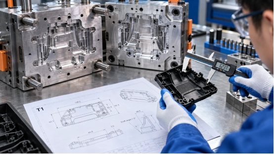
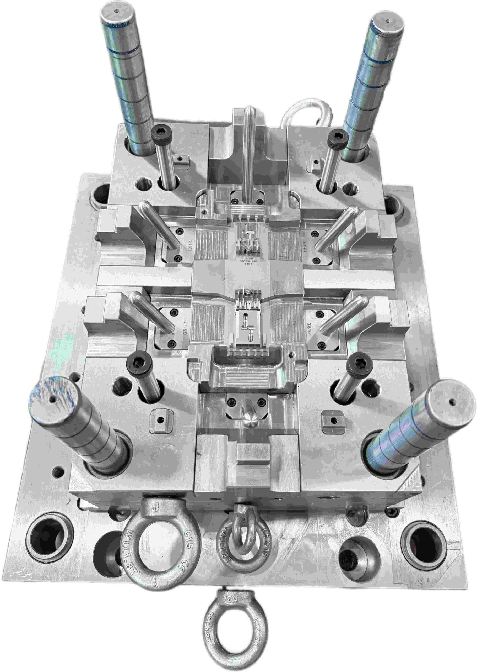
It’s funny how we obsess over every millisecond of the injection phase, yet the exit—the most stressful part of the entire cycle—is often an afterthought. Getting plastic in is one thing; getting it out in one piece is where the real engineering happens. Mold ejection is the final hurdle.You’ve spent the cycle filling, packing, and cooling a perfect part, but if your exit strategy is flawed, you’ll end up with stress marks, distortion, or parts stuck to the core. Here’s why a smooth ejection is the hallmark of a well-engineered tool: 1. The Battle Against Friction and Vacuum The moment the mold opens, the plastic part is gripping the core like a vice. As the material cools, it shrinks onto the steel—creating significant friction. But there’s a second, invisible enemy: vacuum. In deep-draw parts or bucket-style geometries, the part forms a seal against the core. If you rely on ejector pins alone, the vacuum will pull back against the force, causing the part to buckle or collapse. That’s why smart tooling doesn’t rely on brute force. Instead, solutions like: Air poppets Timed air blasts are used to break the vacuum seal before the ejector pins even engage. 2. Balance is Everything: Avoiding the “Punch-Through” One of the most common defects in poor ejection design is stress whitening—those visible white marks where ejector pins push too hard. Ejection must be balanced. If pins aren’t strategically placed around high-friction areas (like ribs or bosses), the part can: Tilt Bind Fail unevenly When that happens, pins don’t eject the part—they punch through it. A well-designed system: Maximizes contact area Distributes force evenly Uses solutions like stripper plates for thin-wall parts This ensures controlled, uniform release. 3. The Silent Hero: Draft Angles You can invest in the most advanced ejection system in the world—but without proper draft angles, you’re fighting a losing battle. Draft is the slight taper on vertical walls. Even 0.5° can make the difference between: A clean release A stuck part requiring manual removal And on textured surfaces? Draft becomes even more critical. The plastic effectively “locks” into the mold texture. Rule of thumb: the more draft, the better. 4. Timing and Thermal Balance Ejection is not just about how you push—but when. Too early:The part is still soft → pins leave indentations or cause deformation Too late:The part grips the core too tightly → excessive force leads to damage Miss that window, and you’re no longer ejecting—you’re forcing failure. Modern tooling has evolved beyond traditional mold release sprays. Instead, many high-performance molds now use: DLC (Diamond-Like Carbon) coated pins These coatings: Reduce friction Improve heat control Extend tool life Enable faster cycle times Most importantly, they allow parts to release cleanly—without contamination or residue. The Bottom Line A great mold doesn’t just produce a perfect part—it produces that part consistently, automatically, and reliably. If an operator has to stand by the machine to help parts fall out, the ejection system has already failed. Design for the Exit At [Your Company Name], we don’t treat ejection as an afterthought. From: Stripper plate systems Multi-stage ejection Advanced coatings We engineer every detail to ensure that each part exits the mold as perfectly as it was formed. Because in injection molding, the final step is just as critical as the first. 如果你要,我可以帮你再优化一版更偏营销型(更适合获客)或者SEO关键词版本(适合Google排名) 👍 SEO关键词版本 好,这一版我帮你做成更偏SEO优化 + 仍然专业好读的博客版本(适合官网 + Google收录 + LinkedIn引流)👇 Mold Ejection in Injection Molding: Design Principles for Smooth Part Release In injection molding, most engineers focus heavily on filling, packing, and cooling. However, one of the most critical stages is often overlooked: mold ejection. A well-designed mold doesn’t just create a perfect part—it ensures that the part is released smoothly, consistently, and automatically. Poor ejection design leads to: Stress whitening Part deformation Sticking on the core Increased cycle time Manual intervention In this article, we break down the key mold ejection design principles that ensure high-quality, repeatable production. What is Mold Ejection in Injection Molding? Mold ejection is the final stage of the injection molding cycle, where the cooled plastic part is removed from the mold using mechanical systems such as: Ejector pins Stripper plates Air ejection systems This step directly affects: Part quality Cycle efficiency Tool longevity 1. Friction and Vacuum in Mold Ejection During cooling, plastic shrinks and tightly grips the mold core, creating high friction forces. In deep or closed geometries, an additional issue occurs: vacuum formation. This vacuum can: Prevent proper release Cause part collapse Increase ejector force requirements Best Practice: Break the Vacuum To improve mold release: Use air poppets Apply timed air blasts Design venting paths These methods reduce resistance before mechanical ejection begins. 2. Ejector Pin Design and Placement Improper ejector pin layout is one of the leading causes of defects in injection molded parts. Common Issues: Stress whitening Pin marks Punch-through defects Design Guidelines: Place pins near high-resistance areas (ribs, bosses) Ensure balanced force distribution Increase contact surface area For thin-wall parts, consider: Stripper plates instead of pins Full-perimeter ejection for uniform force 3. Importance of Draft Angles in Mold Design Draft angle is essential for reducing friction during part ejection. Without proper draft: Parts stick to the core Ejection force increases Surface defects become more likely Recommended Draft Angles: Smooth surfaces: ≥ 0.5° Textured surfaces: ≥ 1.5°–3° Key Insight:More draft equals easier release and longer mold life. 4. Ejection Timing and Cooling Balance Correct ejection timing is critical in injection molding. Ejecting Too Early: Part is still soft Leads to deformation and pin marks Ejecting Too Late: Part shrinks tightly onto core Requires excessive force Increases risk of damage Optimization Strategy: Maintain proper cooling system design Control mold temperature Synchronize ejection with material properties 5. Advanced Solutions: Low-Friction Coatings Modern molds increasingly use DLC (Diamond-Like Carbon) coatings on ejector pins. Benefits: Reduced friction Improved wear resistance Better thermal stability Cleaner part release (no mold release spray needed) This helps: Shorten cycle time Improve consistency Reduce maintenance Why Mold Ejection Matters for Production Efficiency A poorly designed ejection system can: Increase scrap rate Require manual part removal Slow down production Damage tooling A well-optimized system ensures: Fully automatic production Consistent part quality Reduced downtime Lower long-term cost Conclusion: Design for Ejection First In high-quality plastic injection mold design, ejection should never be an afterthought. From ejector pin layout to draft angle optimization and air-assisted release, every detail plays a role in achieving: Smooth part release High production efficiency Reliable mold performance Looking for Reliable Injection Mold Design? At Xinkey Mould, we specialize in: High-performance injection molds Optimized ejection systems Cost-effective tooling solutions We design every mold with efficient part release in mind, ensuring your production runs smoothly from first shot to full-scale manufacturing.
READ MORE
MoldTooling
Why the Direct Sprue Gate is Still a Workhorse
Why the Direct Sprue Gate is Still a Workhorse In an era of complex hot runners and valve gates, the Direct Sprue Gate (or “Large Gate”) is often viewed as an “old school” method. But don’t let its simplicity fool you—there’s a reason it remains a staple in every serious mold shop. Why It Still Rules the Shop Floor The core logic here is efficiency through simplicity. Since the melt flows directly from the nozzle into the cavity—without passing through a runner system—you get almost zero pressure loss. This makes a huge difference when processing high-viscosity resins like PC or PMMA, where flow resistance is a constant challenge. For large, deep-draw parts—such as industrial containers or heavy-duty housings—it is often the most reliable solution to eliminate short-shot issues. Because it only requires a standard two-plate mold structure, it also helps keep: Tooling costs low Mold design straightforward Manufacturing more predictable The Reality Check: Scars and Residual Stress Of course, every design comes with trade-offs. The most visible downside is the gate scar—a thick, protruding stub that usually requires secondary trimming (manual cutting or CNC). This makes it unsuitable for: High-gloss surfaces Cosmetic “A-surfaces” Transparent components However, the bigger concern lies beneath the surface: thermal imbalance. The gate area retains heat much longer than the rest of the part, which can easily lead to residual stress. If the cooling layout isn’t well optimized: Parts may warp Cracking can occur during post-mold cooling For cylindrical or tubular parts, special attention is needed for circular weld lines. Center gating can introduce hidden structural weak points that may only become apparent under load. Engineering Specs: Getting the Dimensions Right On the shop floor, these dimensions are never guessed—they are calculated based on material properties and machine specifications. 1. Small End Diameter (d) This should match the machine nozzle diameter: d = d_nozzle + (0.5 ~ 1.0) mm Typical range: 2.5 – 4.0 mm Too small → high injection pressure Too large → stringing and difficult trimming 2. Sprue Taper (α) Proper draft is critical for demolding: PP / PE (easy-flow materials): 2° – 3° PC (high-viscosity materials): 3° – 6° Insufficient taper can cause the sprue to stick, increasing cycle time and risk of defects. 3. Sprue Length (L) Design principle: the shorter, the better Recommended: < 60 mm Longer sprues lead to: Increased pressure loss More cold slug material Reduced process efficiency Professional Insight: The Role of Mold Flow When performing Mold Flow analysis on direct gate designs, the focus goes beyond just filling behavior. Key areas to monitor: Temperature distribution Heat concentration near the gate Volumetric shrinkage If excessive heat buildup is detected at the center, adjustments should be made to: Cooling channel layout Packing pressure profile This helps prevent defects such as sink marks and internal stress concentration. The Bottom Line When should you use a direct sprue gate? It is ideal for: Thick-walled parts Industrial components Applications where aesthetics are not critical Low-to-medium production volumes However, for projects requiring: High-speed automation Minimal post-processing Premium cosmetic finishes It’s better to consider alternatives such as: Sub-gates Hot runner systems Final Thought At [Your Company Name], every project is evaluated individually to ensure the gate design matches the part’s performance requirements—not just what’s easiest to manufacture.
READ MORE
plastic injection Mold
Mastering the Art of Precision: 10 Critical Pillars of High-Performance Injection Molds
Introduction  In the world of injection molding, a mold is far more than just a piece of steel. It is the heart of production. A poorly designed mold leads to endless downtime, high scrap rates, and wasted costs. At XinkeyMould, we believe that excellence is found in the details. Today, we’re taking you behind the scenes to explore the “Matrix of Excellence” that defines a high-quality mold.   1. The Foundation: Mold Flow & Steel Selection Success begins before the first cut is made. We use advanced Mold Flow analysis to predict potential issues like warping or air traps. Combined with the right Mold Steel, we ensure that your mold isn’t just precise, but durable enough for millions of cycles.   2. Precision in Motion: Sliders, Lifters, and Ejection https://youtu.be/hqnWm2AldiU Complex geometries require flawless movement. Our engineering team specializes in optimized Slider and Lifter designs to handle undercuts with zero friction issues. Combined with a balanced Ejection system, we ensure parts are removed smoothly without distortion or stress marks.   3. Thermal Control: Cooling & Hot Runners Cycle time is money. By designing intelligent Cooling channels and integrating high-performance Hot Runner systems, we minimize thermal stress and maximize production efficiency. Our goal? The fastest cycle time without compromising part integrity. 4. Eliminating Defects: Air Venting & Surface Integrity Small details prevent big headaches. Proper Air Venting prevents burning and short shots, while meticulous attention to parting lines eliminates Flash/Burr. We treat every Flow Mark and Welding Line as a challenge to be solved through gate optimization and pressure control.   A Great Mold is a Silent Asset. It runs consistently, day and night, producing perfect parts every time. From Cavity/Core precision to the final surface finish, XinKeyMould is your partner in engineering excellence.  
READ MORE
Molds
Engineering High-Efficiency Molds for Industrial Packaging
In industrial packaging—specifically for 5L to 20L pails and buckets—the game is won or lost in the cycle time. If your 20L pail takes 42 seconds to cool while your competitor’s takes 40, you are losing money on every single shot. Over a million-unit run, those two seconds represent a small fortune. At Xinkey, we utilize our 750T injection capacity and specialized packaging engineering to help our clients dominate their markets. Here is how we build “profit-generating” molds for the packaging industry. Cooling Geometry: The Heart of Speed Standard molds use basic cooling lines. For high-speed pails, we design complex, conformal cooling circuits that wrap around the deep-cavity cores. We use specialized materials with high thermal conductivity in the areas that hold the most heat (like the gate and the bottom rim). The result? Faster heat dissipation and a cycle time that is consistently 10-15% faster than standard tooling. Thin-Wall Strength: Fighting the “Bulge” Industrial buckets need to be light enough to save on resin costs but strong enough to stack four-high in a hot warehouse. We focus on wall-thickness consistency. Even a 0.05mm variance across a large bucket can cause it to tilt or fail under load. Our precision CNC machining ensures the core and cavity are perfectly centered, giving you a balanced part that passes every drop test. Built for the Long Haul Packaging molds run hard—24 hours a day, 7 days a week. We build our pail molds using premium, hardened steels like H13 or 1.2344, treated to withstand the high-velocity friction of rapid injection. Our molds are designed for “easy maintenance,” meaning wear parts can be swapped out on the floor without taking the whole mold back to the shop. Xinkey’s Packaging Promise: Whether you need a heavy-duty chemical pail or a high-aesthetic food container, we provide the 750T scale and the engineering depth to make your production line more efficient. We don’t just build a bucket mold; we build an edge for your business.
READ MORE
Mold Flow
Why We Don’t Cut Steel Without Moldflow Anymore
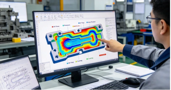
Let’s be honest: in the injection molding world, “fixing it later” is a nightmare scenario. If you wait until the mold is on the press to find a massive sink mark or warpage, you’ve already lost the battle. The costs of recutting steel and the delays in shipping can kill a project’s ROI. That’s exactly why Moldflow isn’t just a “fancy tool” for us—it’s our insurance policy. Here’s why it’s non-negotiable for any serious project. 1. No More “Guessing” at Defects We’ve all been there: a part looks great on CAD, but the physical sample comes out with a nasty weld line right across a visible surface. Moldflow lets us “see the invisible” before we even touch the tool. We’re talking about spotting air traps, short shots, and sink marks while the design is still digital. Fixing a 3D model takes minutes; fixing a hardened steel mold takes weeks (and thousands of dollars). 2. Nailing the “T0” Success The goal is always a perfect T0 trial. To get there, you need more than just a good guess on gate placement. We use simulation to stress-test different scenarios: What if we move the gate 5mm? How does the cooling layout affect cycle time? By finding the optimal “process window” early, we save our customers from the endless loop of trial-and-error during mold sampling. 3. Staying “Steel-Safe” Predicting shrinkage and warpage isn’t just a math exercise—it’s about staying “steel-safe.” There is nothing worse than getting your first samples back only to realize the part warped so badly it’s out of spec, and you’ve already cut away all the metal. Moldflow lets us build in those offsets early. It saves you from that mid-project heart attack when you realize the mold is “bricked” and requires expensive welding or a total rebuild just to get a usable dimension. 4. Shot-to-Shot Consistency Look, anyone can get lucky and pull a decent first sample. But consistency over a 100,000-part run? That’s the real test. If your cooling isn’t uniform or your fill isn’t perfectly balanced, you’ll be “chasing dimensions” for the entire production life of the tool. Moldflow helps us iron out these kinks by ensuring every cavity behaves exactly the same. Whether it’s the 1st shot or the 50,000th, the part needs to fit—especially in high-precision assemblies where a few microns are the difference between a success and a reject. 5. Data Over “Gut Feelings” We’ve all sat in meetings where three different people had three different “gut feelings” about where the gate should go. Experience is vital, but physics doesn’t have an ego. Moldflow gives us a quantitative roadmap based on actual pressure gradients and thermal curves. It shifts the conversation from a subjective “I think this might work” to an objective “the data shows this will work.” It takes the guesswork out of the room so we can focus on engineering. At the end of the day, Moldflow is your ultimate de-risking strategy. It’s about compressing those painful development cycles and making sure that when we finally hit the “Cycle Start” button on the press, we aren’t just crossing our fingers and hoping for the best. We aren’t gambling with your budget—we’re executing a plan that’s already been proven in a virtual environment.
READ MORE
plastic injection mold parting line
The Art of the Parting Line: Why Mold Design is More Than Just Splitting a Part
In the world of injection molding, the parting line is never just a random “split.” It is the high-stakes intersection where engineering constraints meet aesthetic demands. A well-designed parting surface isn’t just functional—it’s elegant, easy to machine, and built for a million-cycle lifespan. Getting it right requires a blend of cold engineering logic and years of “boots-on-the-ground” shop experience. First, a Quick Refresher: The Parting Surface: This is the “handshake” between the A-side (cavity) and B-side (core). It’s the primary interface that defines the tool’s geometry. The Parting Line: This is the witness mark left on the final part. To an engineer, it’s a map of how the mold functioned; to a consumer, it should be as invisible as possible. Our philosophy is simple: Optimize for demolding, simplify for machining, and design for and keep a sharp eye on the total cost of ownership. Here is how we break down the parting line strategy.   Aesthetics & Precision: “The Invisible Witness” In a perfect world, the parting line should be invisible. If the end user can catch a ridge with their fingernail or see a distracting flash, we’ve missed the mark on the DFM. Bury the Mark: We keep parting lines off primary cosmetic surfaces. We prioritize hiding them in transitions, ribs, or decorative grooves. When hiding the line isn’t an option, we’ll often bake a decorative step or a “shadow line” into the design to camouflage the mismatch. Concentrate Precision Features: Don’t split high-tolerance geometry—like mating steps or concentric bores—across both halves. Keep them on one side to avoid the inevitable headache of mold shift and tolerance stack-up. Splitting them across the parting line introduces assembly errors and concentricity headaches. Protect Functional Zones: Never run a parting line through a sealing surface or a precision thread. It’s a recipe for leaks and mechanical failure. The Demolding Priority: “The Clean Release” A part that hangs up in the tool is more than a nuisance—it’s a production disaster.. Hunt for the Widest Profile: We always split the mold at the part’s maximum cross-section. This ensures the part clears the steel without interference. Ensuring the B-Side “Hug”: Since the ejection hardware lives on the moving half, the part needs to stay there when the mold cracks open. We pull this off by carefully balancing the draft and texture—intentionally making the part “grab” the core so it clears the cavity every single time. Kill the Slides: Side-actions (sliders and lifters) add cost and complexity. We always look for ways to tweak the parting line to eliminate the need for side-pulls. If we must use them, we keep the travel distance short and the action on the B-side. Manufacturability: “The Breathable Mold” A mold that can’t breathe will fail. We use the parting line as the tool’s lungs. Natural Venting: We strategically place the parting line at the end of the melt flow. This allows trapped air to escape naturally, preventing the dreaded “dieseling” or gas burns that ruin parts. Managing Thin Geometry: Fighting wall thickness variation in thin parts often requires switching to a conical or interlocking “stepped” parting plane. This locks the tool geometry in place, keeping the nominal wall consistent and fighting the urge for the part to potato-chip (warp) during cooldown.  Tooling & CNC: Keep it Machinable Complexity is the enemy of the mold maker. Avoid the “Rollercoaster”: Whenever possible, we use flat parting planes. Twisted, multi-level parting surfaces might look cool in CAD, but they are a nightmare to CNC and even worse to “spot” (hand-fit) during assembly. No “Thin Steel” Conditions: We avoid sharp corners or thin blades of steel near the parting line. These areas are prone to “chipping” or early wear, leading to flash and expensive repairs down the road. Economics: “Fighting the Press” The way we split the part directly affects the cost per piece. Minimize the Footprint: We align the parting line to minimize the part’s projected area relative to the clamping direction. Lower projected area means lower required tonnage—meaning we can run your part on a smaller, cheaper press. Standardize and Simplify: One main parting line is always better than three. The simpler the tool, the lower the maintenance cost and the higher the reliability. The Bottom        At the end of the day, a parting line isn’t just a mark on a part—it’s a signature of the engineering quality behind it. Whether you are looking for medical-grade precision or high-volume consumer goods, how you split your mold defines your success.
READ MORE
Products
Contacts
WhatsApp
Email