
Inside the Press: A Real-World Look at the Injection Molding Cycle
-
 author
- 13th March 2026
Introduction
In modern manufacturing, injection molding is the heavy hitter for high-volume, precision plastic parts. But for most designers, the magic happens behind closed steel doors. Understanding the mechanical “heartbeat” of the press is the first step toward a design that actually works on the shop floor, not just in a CAD simulation.
Here is how the cycle actually breaks down:
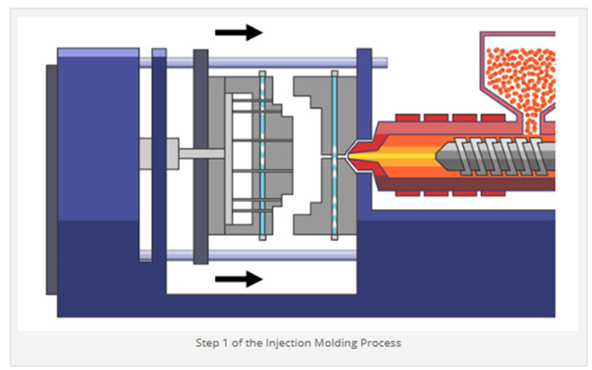
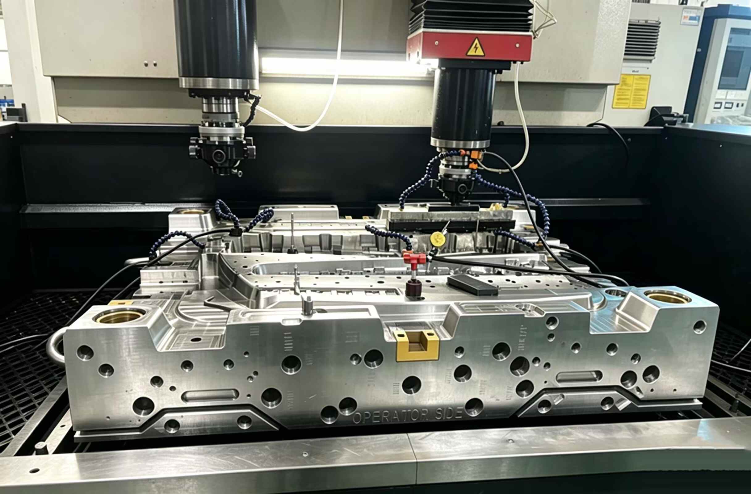
Step 1: The Lockdown (Clamping)
Before a single pellet of resin moves, the press has to secure the tool. We’re talking about massive force here—often hundreds of tons—to keep the A-side and B-side from blowing apart during the shot.
The Pro View: Don’t underestimate surface area. If you’re molding a part the size of a dinner plate, that internal pressure is fighting to force the mold open. Without enough “tonnage” (clamping force), you get flash—that messy plastic bleed that ruins your part’s edges.
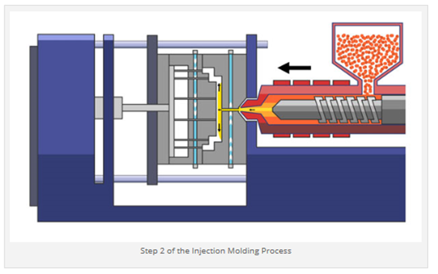
Step 2: The Shot (Injection)
Once the tool is clamped tight, the screw drives forward. This isn’t just a simple fill; it’s a high-velocity ramming of molten resin through the nozzle and into the tool’s geometry.
The Hidden Challenge: Every mold cavity is already full of air. As the plastic slams in, that air needs an immediate exit strategy. This is why we obsess over venting. If that air gets trapped and compressed, it heats up instantly—causing “dieseling” or those ugly black burn marks on your finished part.
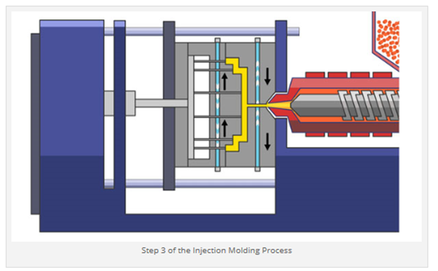
Step 3: The Wait (Cooling)
Fill is done. Now, the clock starts. Cooling is usually the “dead time” in the cycle, yet it accounts for roughly 70% of the total process time.
Physics at Work: We aren’t just letting it sit. We are aggressively pulling heat out via internal water lines.
The Design Reality: This is where uniform wall thickness becomes your best friend. If one section of your part stays hot while another freezes, the part will literally fight itself as it shrinks. The result? Sink marks or that dreaded warpage that sends parts to the scrap bin.
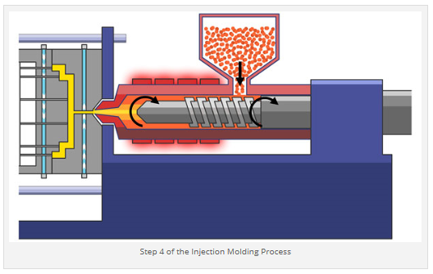
Step 4: Plasticizing – Prepping the Next Shot
The machine is a master multitasker. Even while the current part is still solidifying in the mold, the screw is already backing up to prepare for what’s next.
What’s actually happening: It’s chewing through raw pellets from the hopper, using a brutal combination of heater bands and pure mechanical shear friction to prep the next “shot.” We call this screw recovery, and getting the speed and back pressure right is the secret sauce for a consistent melt density.
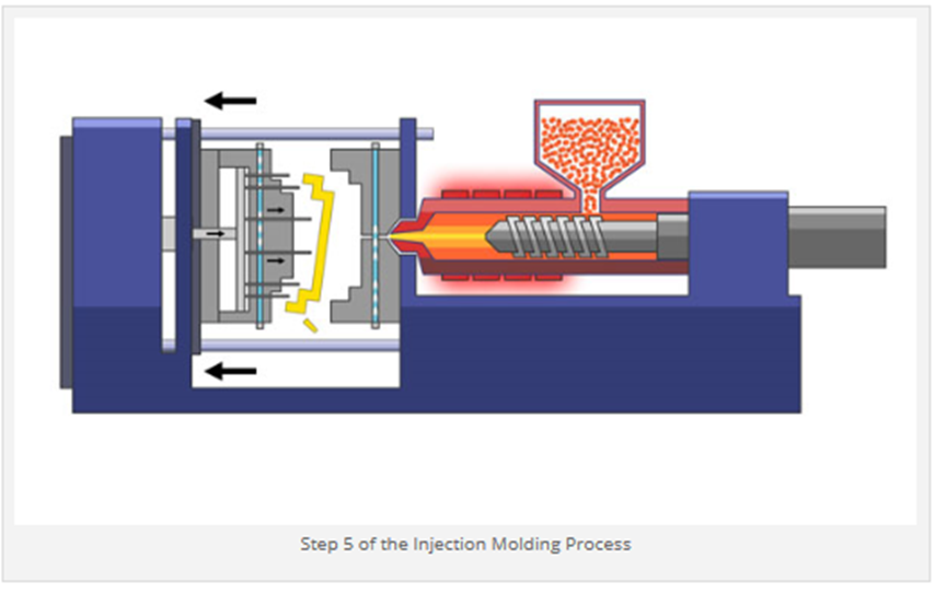
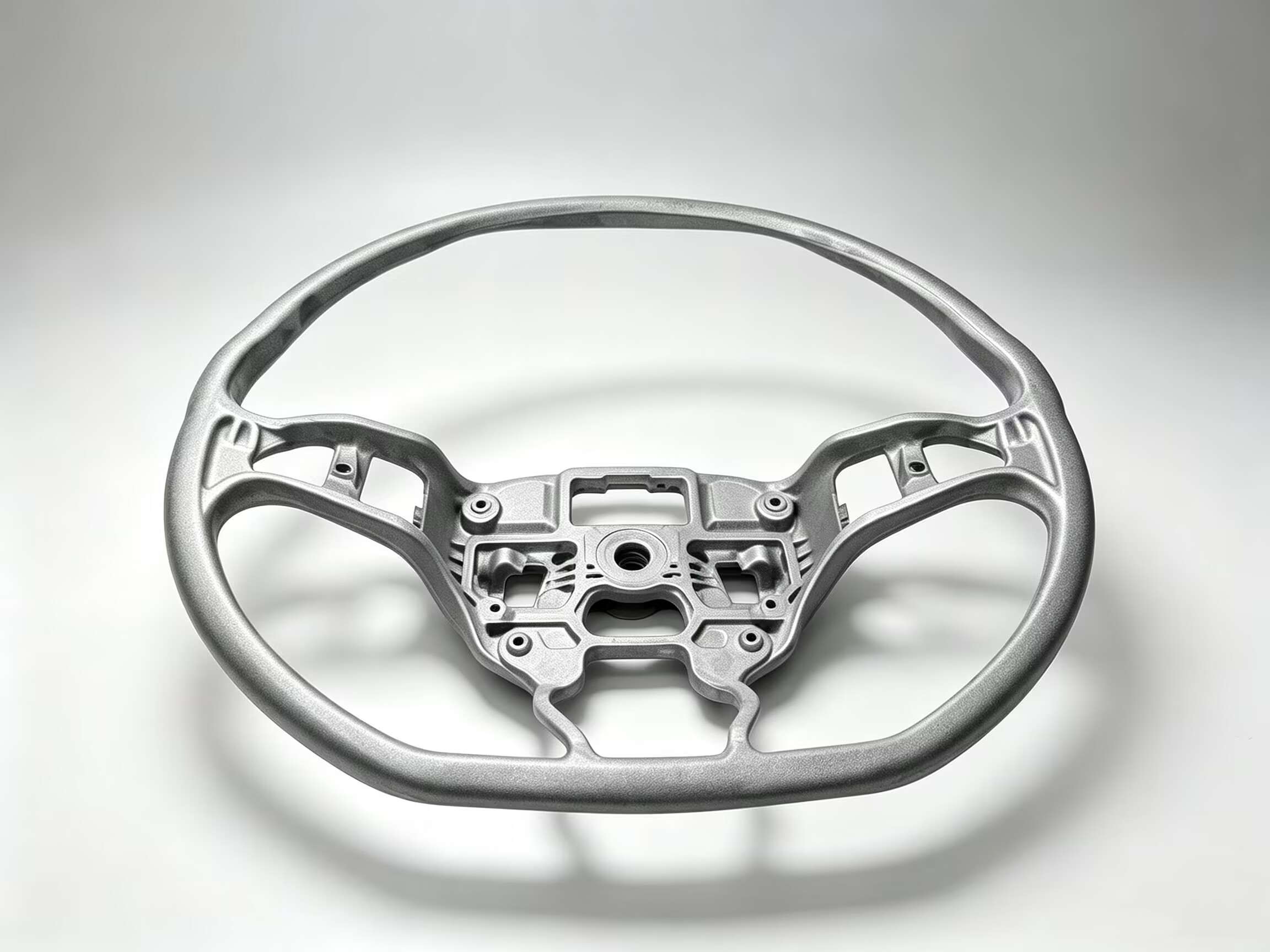
Step 5: Ejection – The Moment of Truth
Once the part hits its target temperature and gains enough structural “backbone,” the mold cracks open.
The Release: This is where the ejector pins—those tiny mechanical fingers—shove the part off the core. If your draft angles aren’t spot on, you’ll hear a “crunch” or see drag marks that ruin a perfectly good finish. It’s the ultimate test of your tool’s design.
Injection molding isn’t just about pushing a button and watching parts fall into a bin. It’s a delicate balance of temperature, pressure, and timing. If you skip the DFM (Design for Manufacturability) stage, you aren’t just risking a bad part—you’re risking your entire production timeline.
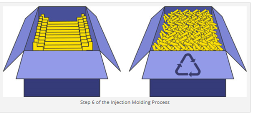
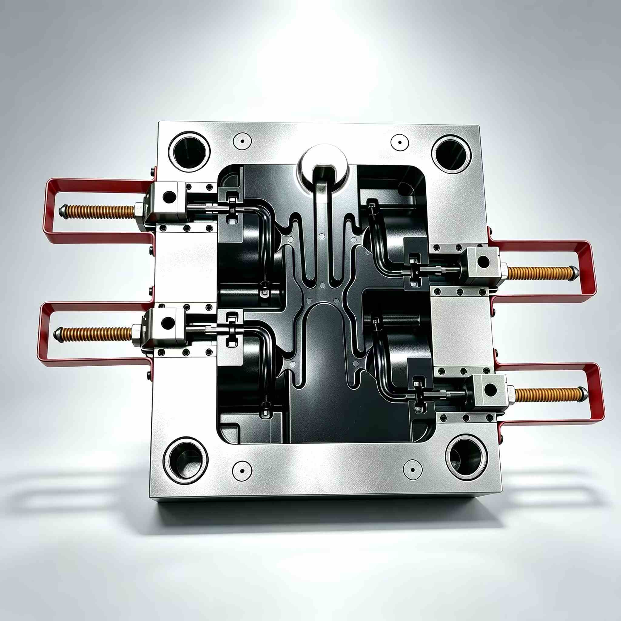
Step 6: Post-Process – Part Recovery & The Runner Strategy
The machine’s internal cycle is over, but the work isn’t done until the part is shelf-ready. Whether it’s dropped into a collection bin or snatched by a robotic arm, the final stage is about separation and logistics. The Pro View: In a standard “cold runner” setup, your part comes out attached to a plastic “scaffolding” (the runner). We clip these off, and in a sustainable shop, those runners are immediately tossed into a granulator to be turned into regrind. This minimizes material waste and keeps your part cost down. The High-Volume Hack: If you’re running millions of units, we’d likely steer you toward a Hot Runner system. While hot runners demand more upfront capital, they streamline the process by bypassing the runner system entirely. You get zero scrap and a much leaner cycle time. After a quick weigh-and-count for accuracy, we box them up and get them moving—on their way to your facility without any unnecessary secondary Ops.
Got a complex design that’s giving you headaches? Don’t wait until you’re on the shop floor to find the flaws. Reach out to our team for a deep-dive DFM analysis, and let’s get your project running as smooth as a hot runner system.


Contact Us