-
Home

-
Capability
- Plastic Injection Molds
- Insert Injection Mold for Metal-Embedded Components

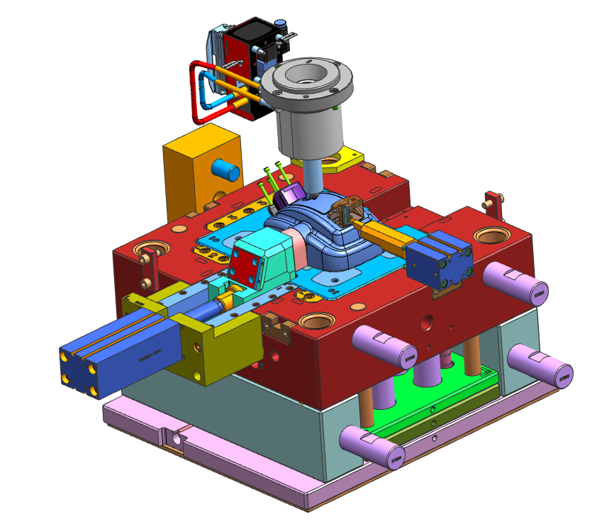
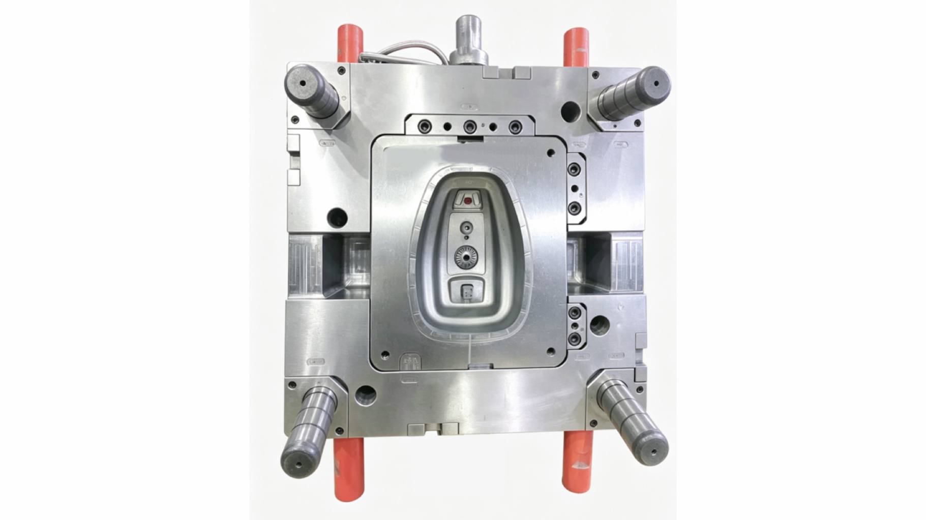
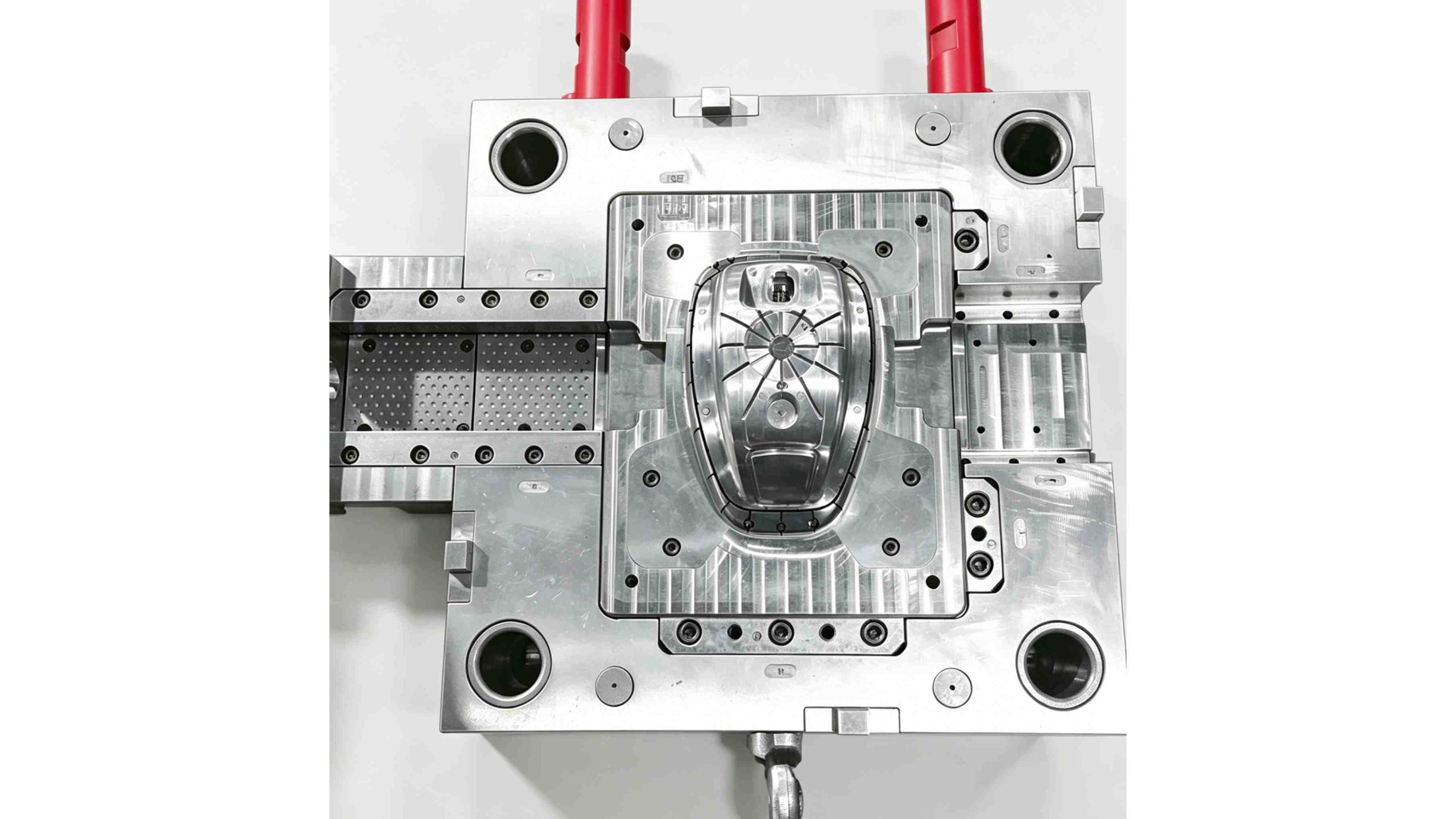
Insert Injection Mold for Metal-Embedded Components
Integrate metal inserts, terminals, magnets, and functional components directly into plastic parts to eliminate secondary assembly and improve structural reliability.
- Strong bonding between inserts and plastic without secondary assembly
- Suitable for metal inserts, terminals, shafts, magnets, and filters
- Stable positioning for thin pins and precision conductive components
- Supports automated insert loading and high-volume production
- Engineering Challenges in Insert Molding Stability
1. Product Overview
An insert injection mold produces plastic parts with metal or other non-plastic components molded directly into the part during injection. The insert—typically a brass threaded bushing, a steel pin, a copper electrical contact, or a stamped metal bracket—is placed into the mold cavity before each shot, then molten plastic flows around it and solidifies, permanently encapsulating the insert. This technique is used where the plastic part needs a durable threaded connection point, where electrical conductivity must pass through a housing wall, or where a metal structural element reinforces a plastic component. At XINKEY MOULD, insert mold engineering focuses on three areas: insert retention so the metal piece does not shift or tilt under injection pressure, thermal management so the cold insert does not cause premature plastic freezing or sink marks, and loading ergonomics so the operator or automation system can place inserts quickly with low error rates.
2. What Problems Can This Product Solve?
Insert Shift Under Injection Pressure
A brass insert sitting on a locating pin looks secure at setup, but the melt front can push it 0.1-0.3mm off position before the cavity fills, resulting in an off-center insert that will not accept its mating screw. XINKEY MOULD uses hardened locating pins with vacuum-assist retention channels and, for critical applications, spring-loaded retention fingers that clamp the insert until the melt front reaches it.
Cold-Insert Defects: Sink Marks and Premature Freezing
When room-temperature metal touches 200°C+ molten plastic, the plastic skins over instantly at the insert surface, creating a weak boundary layer. It also sucks heat from the surrounding melt, causing sink marks on the opposite face. Our molds incorporate insert pre-heating stations and thermal simulation to verify that plastic around the insert stays above its no-flow temperature until the cavity is fully packed.
Flash Into Threaded Insert Areas
The most expensive scrap in insert molding: a threaded brass insert with plastic flash in the threads. The insert must seal against cavity steel in the thread zone—any gap lets plastic flow in. We design insert seating surfaces with controlled interference and use hardened steel shut-offs around thread entries, verified by CMM to within 0.01mm flatness.
3. Typical Applications
Electronic Housings with Threaded Mounting Points
Plastic enclosures for industrial sensors, control boxes, and automotive ECUs where brass or stainless steel threaded inserts provide durable mounting points that survive repeated screw assembly and disassembly without stripping the plastic threads.
Connector and Terminal Overmolding
Electrical connectors where copper or brass pins and terminals are overmolded into a PA66 or PBT housing, creating a sealed, strain-relieved connection point. Insert retention and flash control around the pin are critical—a single stray plastic flash filament across a connector face can cause electrical failure.
Metal-Reinforced Structural Brackets
Automotive brackets, furniture hardware, and appliance mounting plates where a stamped steel or aluminum bracket is overmolded with plastic to combine the strength of metal with the design freedom and weight savings of injection molding.
Threaded Bushings in Plastic Housings
Brass or stainless steel threaded inserts overmolded into pump housings, valve bodies, and industrial equipment covers. The metal thread provides reliable torque retention that plastic threads alone cannot achieve, especially in applications with repeated assembly/disassembly cycles.
4. Specification Table
| Item | Details |
| Mold Type | Insert Injection Mold |
| Insert Types | Brass threaded inserts, steel pins/bushings, copper terminals, stamped brackets, ceramic inserts |
| Insert Loading | Manual, semi-automatic tray feed, or robotic pick-and-place (per volume) |
| Retention Method | Locating pins, vacuum channels, spring-loaded fingers (per insert design) |
| Insert Positioning | ±0.03mm standard; ±0.02mm for precision connectors |
| Pre-Heating | Available for inserts requiring thermal management |
| Sensor Verification | Cavity-loaded sensors to prevent mold closure without inserts |
| Mold Steel | H13/S136; D2 at insert seating and shut-off surfaces |
| Typical Part Materials | PA6, PA66 GF30, PBT, PC, ABS, PP (with chemical bonding treatment) |
| Design Support | DFM, insert retention analysis, thermal simulation, mold flow |
| Trial Support | T1 sampling, insert fit verification, pull-out force test, cross-section analysis |
5. Project Process & Quality Control
Phase 1: Insert Design Review & DFM
Action:Review insert drawing and part CAD. Check insert geometry for moldability: adequate seating surface, no undercuts that trap the insert in the molded part, thermal expansion allowance. Recommend insert modifications if needed.
QC Focus:DFM report: insert seating analysis, retention method selection, thermal impact assessment, loading time estimate per cycle.
Phase 2: Mold Design with Retention Engineering
Action:3D mold design: insert locating system (pins, vacuum, or fingers), shut-off surfaces around insert entry, cooling layout avoiding insert locations, loading access ergonomics.
QC Focus:Retention force calculation: retention must exceed injection pressure force by minimum 2×. Shut-off surface flatness specification. Loading clearance verification.
Phase 3: Precision Machining & Insert Fit
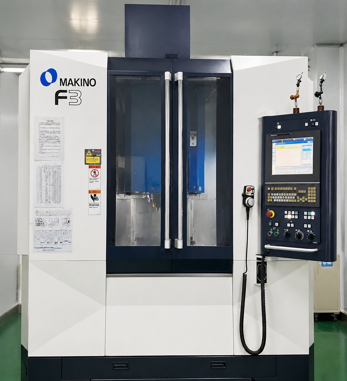
Action:CNC machining of cavity with insert seating surfaces. Shut-off surfaces precision-ground. Locating pins hardened and ground to diameter tolerance.
QC Focus:Insert fit check on every cavity: insert must seat within 0.01mm of design position. Shut-off surface flatness CMM verification. Locating pin diameter check.
Phase 4: Assembly & Loading Test
Action:Full assembly. Manual insert loading test: measure loading time per cavity, verify sensor activation on insert placement, test dry-cycle with inserts.
QC Focus:Loading ergonomics report. Sensor signal verification on every cavity. Dry-cycle test: 50 cycles with insert placement, no false-positive sensor triggers.
Phase 5: T1 Trial
Action:Trial with inserts. Optimize injection parameters: insert pre-heat setting, injection speed, packing pressure, cooling time. Sample parts for insert retention and flash inspection.
QC Focus:Insert position verification via X-ray or cross-section on first article. Torque-to-failure test on threaded inserts. Flash inspection around insert entry. Full dimensional report.
Phase 6: Final Inspection & Delivery
Action:Final cleaning, anti-rust, packing with insert loading guide, sensor wiring diagram, and spare locating pin set.
QC Focus:Full documentation: trial report, insert retention test data, process parameters, loading guide, and maintenance instructions.
6. Why Choose XINKEY MOULD
Insert Retention: Our Engineering Focus
We do not assume that a locating pin alone will hold an insert in place under high-pressure melt flow. Every insert mold project goes through a retention force calculation and, where needed, we add vacuum channels or spring-loaded mechanical retention. This engineering discipline reduces reject rates from insert shift—the most expensive scrap in insert molding.
Thermal Compensation Built In
The mismatch between 25°C metal and 200°C+ plastic is the root cause of sink marks and weak bonding around inserts. Our mold design includes pre-heating recommendations, thermal simulation around the insert zone, and cooling layout that avoids cold spots near inserts.
Sensor Verification for Production Safety
A mold closing without inserts damages both the tool and the press. Our insert molds incorporate cavity-loaded sensors that confirm every insert is in place before the mold closes. The sensor logic is documented and wired for easy integration with your press’s control system.
Flexible Loading for Your Volume
Whether you are running 5,000 parts per year with manual insert placement or 500,000 with robotic loading, we design the mold ergonomics and automation interface to match your production reality. Manual tools get quick-access loading stations; automated tools get standardized pick-and-place interfaces.
7. FAQ
Q1: What types of inserts can be overmolded in an insert injection mold?
Common inserts include brass threaded bushings, steel locating pins and bushings, copper or brass electrical terminals, stamped metal brackets, and ceramic components. The insert must have a geometry that allows it to be securely held in the cavity and encapsulated by the plastic without creating weak spots or stress concentrations.
Q2: How accurate is insert positioning in the molded part?
Standard insert positioning tolerance is ±0.03mm. For precision connectors where insert position affects electrical contact alignment, we achieve ±0.02mm with enhanced retention design and process control. The tolerance is verified on T1 samples via CMM or X-ray measurement.
Q3: Does the insert need to be pre-heated before molding?
It depends on the insert material and size, the plastic being molded, and the part geometry. Large metal inserts or inserts in high-temperature engineering resins typically benefit from pre-heating to avoid premature plastic freezing and sink marks. We evaluate this during DFM and provide a pre-heating recommendation if needed.
Q4: Can a single mold produce parts with multiple different inserts?
Yes, as long as the loading time per shot is acceptable for your cycle time target. A mold can accommodate multiple insert types in the same shot—for example, a brass threaded bushing and a steel locating pin in the same part. Each insert station has its own retention and sensor verification.
Q5: What information should I provide for an insert mold quotation?
3D CAD of the plastic part (STEP/IGES), 2D drawing of each insert type with material specification (e.g., brass C36000), the target plastic material, annual production volume, and preferred loading method. If the inserts are not your design, we also need the insert supplier’s drawing and tolerance specification.
Products
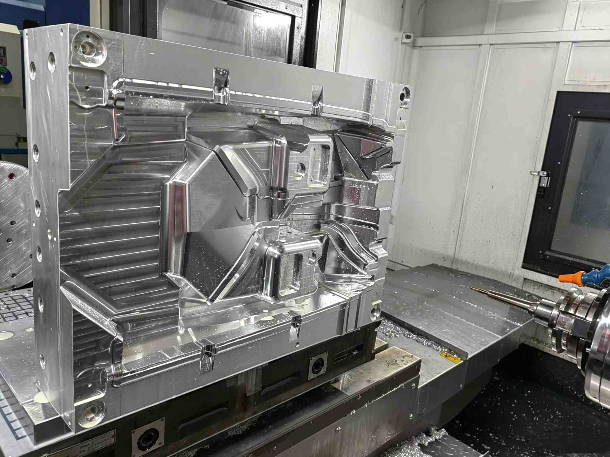
CNC Milling & Turning
5-Axis CNC Milling & Turning — Precision 5-axis mill-turn machining for prototype-to-production metal and plastic components. Single-setup multi-face milling combined with CNC turning on one platform eliminates part transfer between machines, delivering ±0.01mm true-position accuracy with zero setup-to-setup tolerance stack. Full-service CNC machining for aluminum, steel, stainless steel, brass, POM, PEEK, and engineering plastics.
Learn More
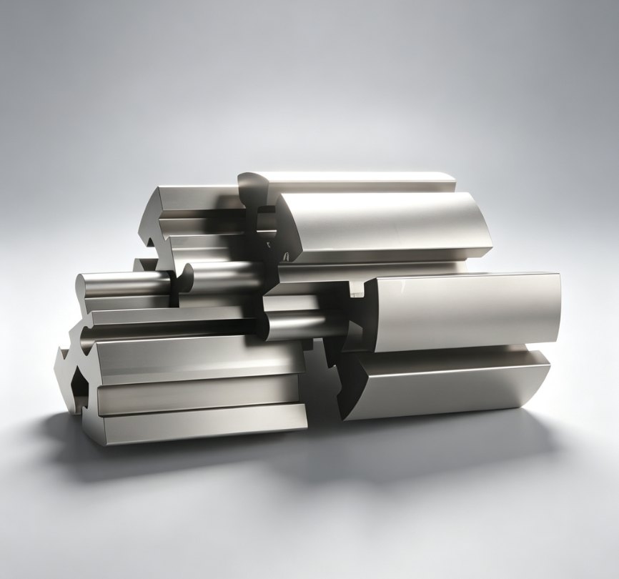
Wire Cut
Wire Cut EDM — Precision wire electrical discharge machining for complex 2D profiles, tight-tolerance die components, and hardened steel parts that cannot be milled. Achieves ±0.003mm accuracy and Ra 0.2µm surface finish on tool steel, carbide, and conductive hard metals. Core service for injection mold inserts, stamping die components, and precision gauge tooling.
Learn More
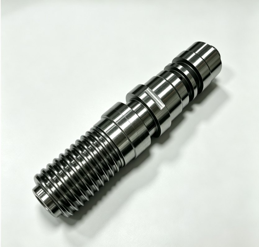
5-Axis CNC Machining
5-Axis CNC Machining — Simultaneous 5-axis contouring for complex 3D surfaces, undercut geometries, and multi-sided parts in a single setup. Eliminates multiple fixturing operations and cumulative tolerance error. Ideal for impellers, turbine blades, orthopedic implants, and injection mold 3D cavity surfaces.
Learn More
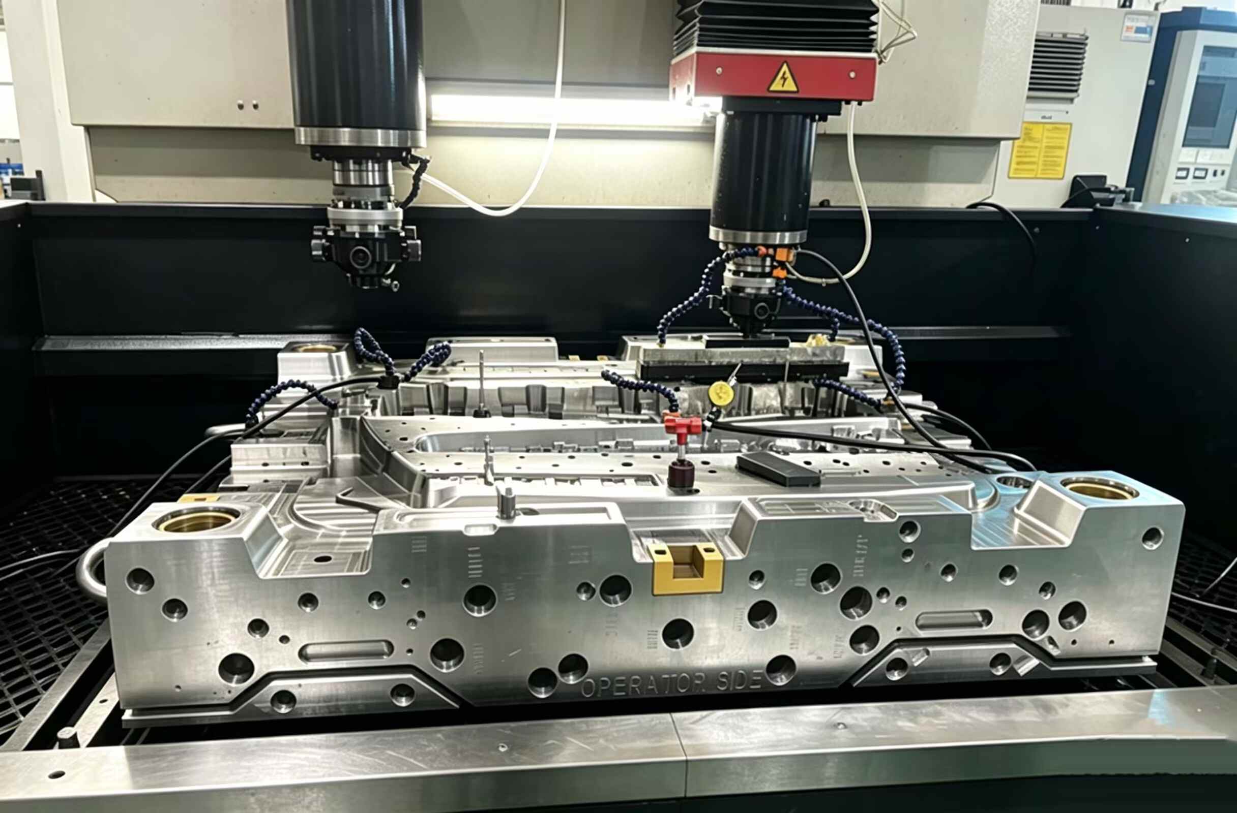
EDM Spark Erosion
EDM Spark Erosion — Sinker EDM precision cavity machining for sharp internal corners, deep ribs, and complex 3D geometries in hardened tool steel. Uses custom-machined graphite or copper electrodes to erode features that rotating cutting tools cannot reach. Core process for injection mold cavities, die casting tooling, and blind-pocket features requiring ±0.005mm accuracy.
Learn More
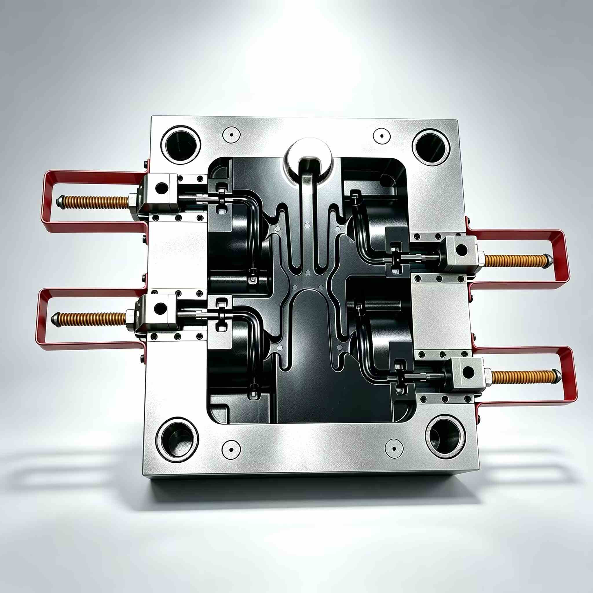
Zinc Die Casting Mold & Parts
Zinc Die Casting Mold — Hot-chamber precision tooling for high-speed zinc alloy components. Designed for thin-wall, net-shape production of automotive trim, electronic housings, and consumer hardware at cycle times as fast as 3-5 seconds with consistent as-cast surface quality.
Learn More
Magnesium Die Casting Mold & Parts
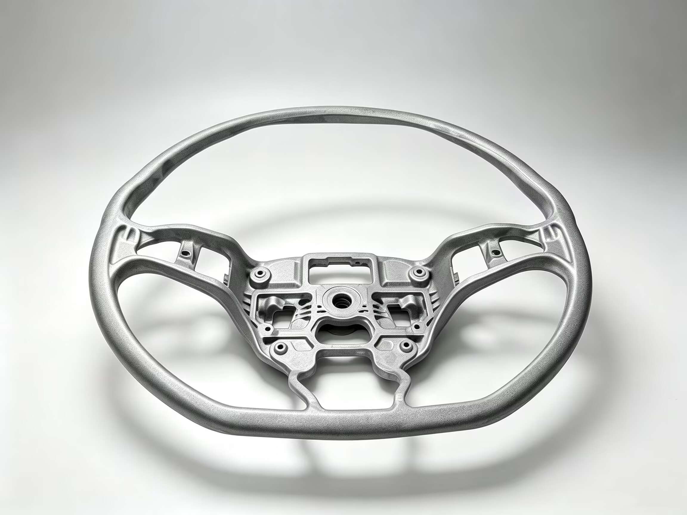
Magnesium Die Casting Mold — Cold-chamber high-pressure tooling engineered for AZ91D, AM60B, and AS41B magnesium alloys. Purpose-built for automotive lightweighting, aerospace housings, and portable electronics where every gram counts. Delivers net-shape components at 1.8 g/cm³ — 33% lighter than aluminum and 75% lighter than steel.
Learn More
Latest News
- 23rd October 2026
Low-Volume Injection Molding: On-Demand Production & Fast Tooling
Why does Low-Volume Injection Molding Fit Uncertain Demand?
Low-volume injection molding gives you a production path when demand moves. You can make saleable parts, validate a design, and learn from field use before committing to a large steel tool.
On-demand production lets you buy smaller releases, keeping cash and warehouse space tied to real orders. Aluminum tooling can bridge a prototype and stable production. The choice depends on geometry, resin, quantity, and change cost.
When does On-Demand Production Make Sense?
Use it for a new product with uncertain demand, irregular replacement orders, or planned design revisions. It suits medical, laboratory, smart hardware, and industrial products that need hundreds or a few thousand validated parts. The run can expose fit, assembly, and surface issues while tool changes remain manageable.
What does Fast Tooling Change?
Fast tooling compresses the time between a frozen CAD file and useful parts. A practical route combines a rapid tooling review, mold design, CNC machining, trial molding, and a T1 check. The goal is a controlled learning cycle. Aluminum tooling can suit early production and provide data for a later hardened mold.
How does the Process Control Tooling and Production Risk?
Low-volume injection molding production still needs production-grade thinking. A short run can hide a poor gate or unstable cooling layout, then repeat the problem as demand rises. Review the part, mold, and press together so each decision has a measurable reason.
What Happens in an Injection Molding DFM Review?
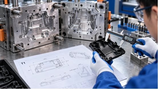
An injection molding DFM review checks wall thickness, draft, parting line, gate, venting, ejection, shrinkage, and press tonnage. Mold-flow simulation can show filling balance, air traps, weld lines, and cooling differences before steel is cut. This mold design for manufacturability step also flags undercuts that may need sliders, lifters, or inserts. Marked-up CAD views show the cost and schedule effect of each change.
How are Tooling and Samples Verified?
After machining, trial molding checks the cavity, runner, cooling, and ejection systems. Record T0 findings, correct root causes, and review T1 parts against the drawing. Ask for the inspection method, resin lot, and sample process conditions.
Which Quality Features Need a CTQ Plan?
Mark CTQ features where a dimensional shift affects sealing, fit, force, optics, or electrical safety. Link each CTQ to a gauge or CMM check, sampling frequency, and limit. This keeps a low-volume trial run useful for repeat orders and gives evidence beyond a visual sample.
Which Part Design Choices Affect Cost and Speed?
Part geometry sets much of your tooling cost before a purchase order. Design edits can shorten injection molding lead time, reduce secondary work, and simplify plastic injection mold maintenance.
How Much Draft Angle Do You Need?
Add a draft angle to faces that pull along the opening direction. Textured faces and deep ribs usually need more draft than smooth faces. Review the parting line with the ejection plan so the part stays on the moving side and leaves the cavity cleanly. This small check prevents drag marks, whitening, and stuck parts during sampling.
Why does Wall Thickness Matter?
Keep wall thickness as even as the function allows. A common starting range for many thermoplastics is about 1 to 3.5 mm, followed by a resin-specific review. Thick zones cool slowly and can create sink marks; thin zones can restrict filling. Use ribs, bosses, and gussets that support the part while keeping section mass compatible with the cooling cycle.
Where do Radii and Vents Help?
Use internal radii at corners to lower stress and match the cutting path of an end mill. Put vents near the end of melt flow so trapped air can leave. Good venting supports filling and reduces burn marks.
How should You Specify Surface Finish?
Choose the finish that matches function and viewing distance. A polished cavity adds hand work and schedule. A machined or light-texture finish may meet the requirement with a simpler tool. State the finish by area.
How should You Plan Quantity, Materials, and Tool Life?
Quantity planning connects your forecast to mold structure. Review the next 12 to 24 months, order pattern, and finished-goods cost before choosing cavity count or steel grade.
Is a Single-Cavity or Multi-Cavity Mold Better?
A single-cavity mold keeps early tooling and change work easier to control. A multi-cavity mold can lower the piece price when demand is steady, provided geometry and runner balance support even filling.
Family molds can combine related parts for a pilot production run, but each cavity needs its own inspection limits. Ask for a cycle-time and capacity comparison, then select cavities with demand in view.
Which Material Fits a Bridge Production Run?
Select resin by strength, heat, chemicals, color, and regulatory need. PP, ABS, PC, PA, POM, and filled grades differ in shrinkage and cooling. Share the final material early so gate, vent, cooling, and steel decisions match it.
When should You Move to a Hardened Tool?
Move when demand, wear, or dimensional stability justifies the capital. Aluminum tooling can carry early on-demand production and design learning. A hardened steel mold fits a repeat program with higher shot counts, tighter process windows, or long service expectations. Keep the CAD, inspection data, and approved process settings from the first tool so the next tool starts with evidence.
What should You Ask a Supplier Before Ordering?
Your supplier conversation should end with numbers, documents, and named owners. The checklist below helps you compare a quote by total project risk and tooling cost.
Which Questions Clarify the Real Schedule?
Ask for DFM timing, tool build days, first trial date, correction allowance, sample quantity, and the expected injection molding lead time. Confirm who approves material substitutions and how an engineering change affects the quote. A supplier that supports low-volume trial production should also explain how it will scale to small-batch production or bridge production after approval.
Which Records Support a Purchase Decision?
Request the DFM report, mold-flow findings when used, steel and heat-treatment records, CTQ dimensional reports, and the T1/T2 issue list. Ask how cooling, venting, ejection, and wear parts will be checked. These records support tool release.
Where Can Engineering Support Shorten the Route to Production?
For projects that need both rapid tooling and a low-volume injection molding production plan, XINKEY MOULD works from the product-design stage through DFM, mold design, machining, trial molding, and small-batch production. Its engineering workflow covers wall thickness, draft angle, gate and runner balance, flow analysis, cooling, venting, and ejection before tooling starts.
The team also handles sliders, lifters, inserts, threaded cores, and two-shot structures when the part needs them. Multi-stage machining checks and trial-molding verification create a traceable handoff into pilot production. If you need to compare a rapid prototype mold with a production-ready plastic injection mold, share the CAD file, resin, CTQ features, expected quantity, and target date so the quote reflects the actual decision.
FAQ
Q1: What is low-volume injection molding used for?
A: It produces saleable parts for design validation, market testing, replacement demand, and early production before a larger tooling investment.
Q2: How does aluminum tooling affect fast tooling?
A: Aluminum tooling supports quick machining and practical revisions for early runs. Tool life and resin choice still need a project-specific review.
Q3: What information should you send for an injection molding DFM review?
A: Send the 3D CAD file, 2D drawing, resin and color, annual and first-run quantity, CTQ dimensions, finish callouts, and target date.
Q4: How long is the injection molding lead time?
A: It depends on geometry, mold structure, material, inspection needs, and revision rounds. Ask for separate dates for DFM, tool completion, T1 samples, corrections, and shipment.
Q5: When does a multi-cavity mold make sense?
A: It fits steady demand where balanced filling and shared inspection controls can lower the part cost. A single-cavity tool often suits early learning and changing designs.
- 22nd October 2026
5 Benefits Of Rapid Tooling For Automotive Injection Molding
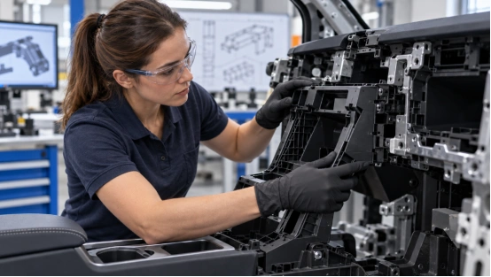
Car projects frequently shift. This usually happens once an initial physical part goes into a dashboard, console, lamp housing, or battery assembly. Rapid tooling for automotive injection molding offers a quick, manageable route. It takes you directly from CAD data to working parts.
These tools might rely on aluminum or soft steel. The exact metal depends on your target volume and chosen resin. The goal remains highly practical. You get to evaluate the piece and process. Plus, you can verify purchasing choices before paying for an expensive, long-lasting production tool.
What Is Rapid Tooling for Automotive Injection Molding?
It acts as a distinct mold-creation method. It fits automotive prototype production and medium-batch runs perfectly. A basic mold utilizes fewer cavities. It also features a very standard ejection setup.
Conversely, standard production molds require tough hardened steel. They need intricate slides, lifters, and balanced runners. Your final choice relies heavily on volume, geometry, resin, visual requirements, and strict delivery deadlines.
1. Faster Structural Changes Before Steel Commitment
The first physical sample exposes decisions that a screen can hide: a rib may interfere with a connector, a draft angle may hold the part on the wrong side, or a gate mark may land on a visible surface. A rapid prototype mold gives your design team a short feedback loop. You can review T1 samples, record the change, and update the part or mold while the project is still flexible.
How Does the Review Work?
Ask for DFM analysis before machining begins. The review should cover wall thickness, draft, parting line, undercuts, ejection, shrinkage, and the intended press.
The engineering record should also show which change affects tool cost, cycle time, or assembly fit. This makes a quote useful for purchasing because you can compare the cost of a revision with the cost of carrying a risky feature into production.
2. Earlier Validation of Automotive Plastic Parts
Automotive rapid injection molding lets you test structural features with a real molded part. Deep cavities, thin walls, ribs, bosses, and snap fits behave differently under filling, packing, cooling, and ejection. A digital model can guide the review, yet a physical sample still needs fit checks, load checks, surface review, and dimensional measurement.
Where Does Mold Flow Analysis Help?
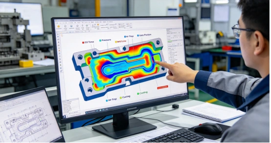
Mold flow analysis maps gate position, runner balance, filling pattern, weld lines, air traps, shrinkage, and warpage and sink marks before steel is cut. The result is a mold design validation record that points to a specific action, such as moving a gate, changing a rib, adding a vent, or adjusting a cooling circuit.
For complex mold structures, this early work reduces the chance of discovering a slider, lifter, or insert problem during a late trial.
3. Better Control of Prototype Spending
Prototype tooling turns a large tooling decision into staged purchasing. You can order a defined quantity for fit, durability, and user testing, then decide whether the geometry merits a production tool. This fits projects that need low-volume injection molding for a pilot build, a customer trial, or a limited vehicle release.
What Should Purchasing Compare?
Compare the tool price with revision cost, resin usage, inspection time, machine size, and the value of the parts being tested. Ask whether the tool can be modified, whether wear parts are replaceable, and which dimensions will be measured on each sample.
A low entry price loses its value when the tool cannot support the next test or when every change requires a new build. A clear inspection plan also helps engineering, quality, and purchasing agree on the release decision.
4. Shorter Lead Times for Testing and Launch Decisions
Rapid tooling for automotive parts can move first shots into a working press in days or a few weeks, depending on geometry, material, and tool construction. CNC-machined aluminum or soft tooling often suits an early run. The supplier still needs time for design review, machining, assembly, trial molding, and corrections, so a realistic schedule matters more than a headline number.
Which Process Details Affect the Schedule?
Injection molding cycle time depends heavily on wall thickness, resin, mold temperature, and cooling layout. Well-planned mold cooling channels remove heat from thick areas and reduce the wait before ejection. Venting, runner balance, and a stable ejection system also affect the number of trial loops. When you request a quote, ask for milestones for DFM approval, steel release, first trial, dimensional report, and sample shipment.
5. A More Practical Mass Production Transition
Rapid tooling can use production-grade plastics, so the samples can represent the mechanical behavior, appearance, and assembly feel expected from the final part. The tool itself may have a shorter service life than a hardened production mold. That distinction should be written into the sourcing plan.
How Do You Plan the Handover?
Carry the approved CAD revision, resin grade, shrinkage data, gate location, cooling notes, and inspection results into the automotive injection molding tooling package.
A multi-cavity mold may need a new runner balance study and a different press condition. Treat the prototype run as process learning: record fill time, packing, cooling, ejection, and key dimensions. Those records shorten the mass production transition and give the production team a starting process window.
What Should You Look for in a Rapid Tooling Partner?
The practical value of a rapid tool comes from decisions made before cutting steel. XINKEY MOULD uses an engineering-first workflow that starts with DFM analysis and mold flow analysis, then moves through mold design, precision machining, trial molding, and verification.
Its team includes 22 in-house designers, with support for rapid T1 samples, low-volume injection molding, sliders, lifters, inserts, hot or cold runners, and cooling-system design. The automotive workflow includes an IATF-aligned process and PPAP documentation available on request.
For buyers comparing suppliers, the useful question is whether the same team can carry approved changes into production tooling. Its injection mold engineering solutions cover that design-to-sampling handoff and keep the release record tied to the mold revision.
FAQ
Q1: What is rapid tooling for automotive injection molding used for?
A: It produces early automotive plastic parts for fit checks, functional tests, pilot builds, and market or customer review before a long-life production mold is released.
Q2: When should you request DFM analysis?
A: Request DFM analysis before steel machining. Review wall thickness, draft, parting line, gates, ejection, cooling, shrinkage, and press requirements while design changes remain manageable.
Q3: Can rapid tooling support PPAP documentation?
A: The supplier can prepare PPAP documentation when the project quality plan calls for it. Confirm the required records, dimensional reports, material certificates, and process data before the first trial.
Q4: How fast can a rapid prototype mold deliver T1 samples?
A: A simple tool may reach T1 samples in days or a few weeks. Geometry, resin, tool material, cavity count, and the number of trial corrections set the actual schedule.
Q5: Does rapid tooling replace a production mold?
A: It supports prototype and bridge quantities. A hardened production mold is usually required for high shot counts, multi-cavity output, tight process control, and long service life.
- 15th October 2026
5 Strategic Benefits of Outsourcing Rapid Tooling
A launch date can slip long before the first molded part. The delay often starts with a wall thickness that traps heat, a weak draft angle, or a late gate decision. Outsourcing rapid tooling puts engineering, machining, trial molding, and measured samples on one project path.
A capable tooling supplier connects speed with part quality and a credible route to production through rapid tooling services.
Benefit 1, Shorten Your Time to Market
Rapid tooling compresses the work between a released CAD file and a tested molded part. Engineering review, material planning, mold design, and machine scheduling can start from the same controlled data set.
Run Design and Manufacturing Work in Parallel
An outside team can review draft, wall thickness, undercuts, parting lines, gate position, ejection, and cooling while your product team closes cosmetic details. That overlap may remove several handoffs. It also gives procurement one schedule covering tool design, machining, assembly, trial, inspection, and sample shipment.
Set a Clear Sample Milestone
Ask the supplier to quote a date for T1 samples and list the inputs that control it. Standard tools may reach T1 in two to four weeks. Unscrewing or two-material tools can take four to eight weeks. Complexity, steel choice, bought-in components, and CAD changes still affect time to market.
Benefit 2, Turn Tooling Cost into a Controlled Project Budget
Internal tooling requires design hours, CNC and EDM capacity, assembly skill, press time, metrology, and corrections. Outsourcing places those items inside a defined project scope for comparison against launch volume.
Compare the Full Cost of Ownership
Compare quotations by total project cost. Repeated sampling, steel welding, long cycles, and early wear all add expense. Ask each tooling supplier to state the mold steel, expected life, cavity count, runner type, replaceable wear parts, inspection scope, trial rounds, and change policy.
Match the Tool to Expected Volume
A rapid prototype mold can use a simpler layout and steel suited to design validation or an early market run. A production tool needs balanced cooling, durable sliding parts, controlled hardness, and maintenance access. Share annual volume and likely product revisions before the quote.
Benefit 3, Find Design Risks Before Steel Is Cut
Small CAD choices can create large tool changes. Thin ribs may fill poorly, thick bosses can sink, limited draft can mark the surface, and an undercut may require a slider or lifter. Early engineering review gives you time to change the part file while the change is still simple.
Review the Part through DFM
A useful DFM analysis marks wall thickness, draft, shutoffs, parting lines, ejection points, tolerances, surface requirements, and assembly interfaces. It should also explain why each item matters.
For example, keeping a concentric bore on one mold half reduces mold-shift and tolerance-stack risk. A purchasing team can then approve the tool scope with visible technical reasons.
Test Flow, Cooling, and Warpage Digitally
Mold flow analysis can compare gate positions, pressure, weld lines, air traps, shrinkage, cooling, and warpage before machining. Moving a gate 5 mm in a simulation is a short task. A change after steel cutting can require welding, machining, polishing, and another trial.
Benefit 4, Validate Materials with Production-Like Parts
A printed prototype answers fit and appearance questions. It rarely reproduces resin flow, fiber orientation, shrinkage, weld lines, sink, or ejection behavior from molding. Rapid injection molding gives you parts made with the intended resin and a process close to the planned production method.
Test the Resin in the Intended Process
Use molded samples to compare candidate resins for stiffness, impact, heat, chemical exposure, sealing, color, and surface finish. Process details matter. Phenolic materials, for example, require controlled mold heat and effective venting. Insert-molded parts need secure insert location under injection pressure. Two-material parts need a sound bonding interface and accurate tool alignment.
Use Measured Samples for Decisions
Define the sample plan before the tool trial. Record resin grade, drying condition, melt and mold temperatures, pressure, cycle time, and cavity number. Then inspect critical dimensions and run the product tests that decide release.
A nice-looking sample can still hide a weak process window. Measured evidence gives engineering and purchasing the same basis for approval.
Benefit 5, Create a Practical Bridge to Mass Production
The first acceptable shot proves that the tool can make a part. Pilot runs test repeatability across cavities, shifts, and material lots. Outsourcing rapid tooling delivers the planned value when one team carries the project through sampling and early production.
Stabilize the Process during Pilot Runs
Low-volume production and bridge production let you supply launch units while the team checks cycle time, scrap, dimensional drift, assembly fit, packaging, and maintenance needs. Engineers can tune cooling, venting, packing, and ejection with direct access to the tool. That continuity matters when a defect appears only after a longer run.
Protect Return on Tooling Investment
Earlier sales help recover the tool investment, though repeatable output drives the larger return. Review yield, labor content, resin use, cycle time, press tonnage, and wear-part access. A parting-line choice that lowers projected area may allow a smaller press. A hot runner may cut runner waste at high volume. Each decision should connect to your forecast and unit-cost target.
What Should You Expect from an Engineering-Led Tooling Partner?
The five benefits depend on one connected engineering record from DFM through trial molding. XINKEY MOULD assigns 22 in-house designers to product review, mold design, and mold flow analysis. Its documented process covers wall thickness, draft, parting lines, sliders, lifters, cooling, venting, ejection, and material selection before machining. High-precision CNC work reaches ±0.01 mm-level control, and molding equipment spans 90T to 750T for sampling and production handoff.
For a buyer, the useful point is continuity. The same project can move from a 24-hour DFM report to tooling, T1 inspection, pilot quantities, and injection mold manufacturing. That structure makes design changes, sample findings, and production settings easier to trace. You can request a project review with the CAD file, resin, annual volume, finish, tolerance, and target sample date.
FAQ
Q1: When Should You Outsource Rapid Tooling?
A: Outsource when your launch plan needs molded parts sooner than your internal engineering, machining, or press capacity allows. It also suits projects that need DFM, material trials, or a direct path into pilot production.
Q2: What Files Should You Send for a Rapid Tooling Quote?
A: Send a 3D CAD file, a dimensioned drawing, resin grade, surface requirements, critical tolerances, annual volume, target tool life, and the required T1 date. Add assembly data when mating parts control fit.
Q3: How Can You Compare Tooling Quotes Fairly?
A: Compare steel, cavities, runner system, mold standard, expected life, inspection scope, trial rounds, sample quantity, change terms, lead time, and shipping. A line-by-line comparison reveals what each price includes.
Q4: Can Rapid Tooling Use Production Resin?
A: Yes. A suitable mold can run production resin for functional, dimensional, and assembly tests. Confirm drying, processing temperature, shrinkage allowance, and any fiber or flame-retardant content before tool design.
Q5: Can a Rapid Tool Move into Mass Production?
A: Some tools can support continued production when their steel, cooling, cavity layout, wear parts, and press interface match the volume target. Ask the supplier to state the expected shot life and maintenance plan in the quote.
- 16th October 2026
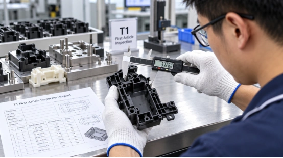
The Strategic Advantages of Short-Run Injection Molding for Complex NPI
Complex new product introduction (NPI) projects rarely fail because the CAD model looks wrong. They fail when a part reaches steel, trial molding exposes a gate or cooling issue, and the schedule has no room for another tooling loop.
Short-run injection molding gives you production-like parts early. You can check fit, function, finish, assembly, and customer response before a full-volume tool absorbs the budget.
What Does Short-Run Injection Molding Add to NPI?
Short-run injection molding uses a production-intent mold and a controlled quantity of parts for design validation, pilot production, or bridge production. The run can be sized around a test plan, such as 100 parts for assembly checks or several thousand parts for a market release. Molded parts and process data provide the evidence for the next tooling decision.
A Physical Test of the Product
Resin shrinkage, weld lines, ejection marks, and actual assembly loads appear in molded parts. A printed model cannot show how a thin wall fills or how a snap fit behaves after cooling. Early molded samples let your team record dimensional data and make a change while the tool remains practical to modify.
A Bridge Between Design and Volume
Bridge production gives you sellable or field-test units while the final multi-cavity tool is being completed. This matters for a new medical accessory, smart device housing, or industrial enclosure with a fixed launch date. The same material family, gate concept, and process window can carry the project into the next tool stage.
Which NPI Risks Can You Control before Full-Volume Tooling?
The largest NPI costs often come from late engineering decisions. A short run creates a checkpoint for the decisions that affect tooling cost, yield, and delivery.
Part Design and DFM Analysis
Start with DFM analysis before cutting steel. Review wall thickness, draft angles, ribs, bosses, undercuts, parting lines, and the projected area that drives press tonnage. A small change to a rib or draft can remove a difficult slide, simplify machining, and reduce a later mold revision.
Flow, Cooling, and Ejection
Moldflow analysis can compare gate positions, runner balance, filling patterns, air traps, and weld lines. Cooling channel layout matters because cooling often occupies about 70% of an injection cycle.
Uneven thermal balance creates sink marks and warpage. Venting gives trapped gas a path out, while a balanced ejector pin, sleeve, lifter, or air-ejection system protects cosmetic surfaces during release.
Complex Geometry and Tolerance
Sliders, lifters, inserts, threaded cores, and two-shot features add movement and tolerance stack-up. A short-run tool lets you inspect those interfaces under real pressure. Check core and cavity alignment, guide pins, runner balance, and the fit of mating features before you commit to a larger cavity count.
How Should You Compare Short-Run Tooling Cost with Production Tooling?
Price the decision across the whole NPI path. A low quote becomes expensive when it creates extra sampling, hand rework, scrap, or a rebuild. A practical sourcing review should include tool steel, machining, trial molding, material waste, engineering time, freight, and the cost of a delayed launch.
Use Volume and Risk Together
Choose a cavity count that matches the validation need. A single-cavity or low-cavity mold can provide fast feedback for a complex enclosure. A multi-cavity tool makes sense after dimensions, resin, and assembly have settled. For high-cycle projects, steel selection and heat treatment affect wear parts, maintenance, and stable output.
Set Acceptance Data Before the Run
Define critical dimensions, cosmetic zones, cycle time, part weight, flash limits, and assembly tests before ordering. Ask for T1 samples, a measurement report, and a short list of open issues. This gives procurement a clear release gate and gives engineering facts for the next tool decision.
What Does a Reliable Short-Run Process Look Like?
The process should connect design review, mold design, machining, trial molding, pilot production, and mass production. Each handoff needs an owner and a measurable output.
A Practical Sequence
Share the 3D data, resin, annual volume, key dimensions, and launch date.
Complete DFM analysis and review Moldflow findings with the design team.
Select the parting line, runner, cooling, venting, ejection, and mold steel.
Machine and assemble the tool, then run T0 or T1 samples.
Measure parts, test assemblies, and record process settings.
Correct the tool or part design, then release a controlled pilot production run.
This sequence keeps the evidence close to the decision. It also makes a handoff to a higher-cavity tool easier because the team has a record of what worked.
How Can an Engineering-Led Supplier Support Complex NPI?
XINKEY MOULD supports short-run injection molding as part of an injection mold engineering workflow. The team starts with DFM analysis, wall thickness and draft review, and Moldflow analysis before tooling. It then connects precision CNC machining, EDM, mold assembly, trial molding, and low-volume production support.
For complex NPI, the useful detail is the handoff: T1 samples are checked against design intent, cooling and venting are reviewed against defects, and slider, lifter, insert, or threaded-core behavior is tested before a volume decision.
The process also covers rapid prototype mold development, pilot production, and bridge production, so procurement can compare a tool plan with a real launch schedule. See the injection mold engineering solutions and custom injection mold products pages for the relevant service scope.
FAQ
Q1: When should you choose short-run injection molding for NPI?
A: Choose it when fit, function, finish, assembly, or market timing needs evidence from production-intent parts before full-volume tooling.
Q2: Can low-volume injection molding use the final production resin?
A: Yes. Use the approved resin grade when the tool, press, and process window support it, then record material lot and drying conditions with the samples.
Q3: How do T1 samples help a procurement decision?
A: T1 samples connect the quoted tool design with measured dimensions, defects, cycle data, and open engineering actions, giving procurement a clear release gate.
Q4: Does a complex injection mold require Moldflow analysis?
A: Moldflow analysis is useful when gates, thin walls, multiple cavities, cooling balance, air traps, or weld lines create meaningful process risk.
Q5: What should you request before pilot production?
A: Request an approved drawing, resin specification, dimensional report, cosmetic standard, process settings, open-issue list, and a correction plan with owners and dates.
- 9th October 2026
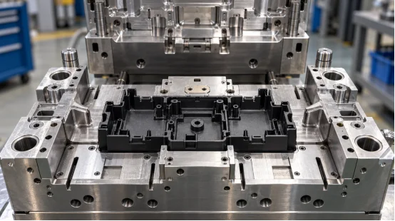
Prototype Injection Molding vs 3D Printing vs CNC Machining
Choosing a prototype process depends on the question you need the parts to answer. A housing for a fit check, a snap-fit cover, and a ten-piece pilot run each need different evidence. This guide compares prototype injection molding, 3D printing, and CNC machining by lead time, material behavior, accuracy, finish, quantity, and purchasing risk.
What Does Each Plastic Prototyping Method Produce?
The three methods build parts in different ways, so the part carries different evidence. Injection molding fills a cavity with molten thermoplastic and repeats the same cycle. 3D printing adds material layer by layer. CNC machining removes material from a solid block. Your intended use should decide which behavior matters most.
Prototype Injection Molding
Prototype injection molding uses a short-run mold, often aluminum or softer tool steel, to make parts from the planned production resin. You can inspect weld lines, sink marks, warpage, snap-fit force, and texture with a molded part.
3D Printing
3D printing suits daily geometry changes or one to five quick parts. FDM can use ABS, PLA, and polycarbonate; resin and powder systems cover finer detail. Layer direction affects strength, stair-step texture, and heat response. A printed hinge may flex differently from an injection-molded hinge with the same nominal polymer.
CNC Machining
CNC machining cuts a part from ABS, POM, nylon, PC, or another engineering plastic block. It gives clean datum references and tight dimensions on accessible features. Internal channels, deep cavities, and thin ribs can raise cost because cutters need access and support. Machined parts also show the block’s grain and tool marks, which can differ from molded texture.
Img.CNC milling machine spindle carving white plastic prototype part.webp
Which Method Fits Your Quantity and Lead Time?
Quantity changes the cost curve. Set a target quantity, sample date, and number of design revisions before comparing quotes.
One to Ten Parts
3D printing suits early form checks because dedicated tooling is unnecessary. CNC machining suits parts needing accurate holes, flat datums, or functional threads. An injection mold prototype makes sense when the decision concerns molded behavior, such as a living hinge or clip.
Ten to Several Hundred Parts
Low-volume injection molding spreads tooling cost across repeatable parts and supports production-grade materials. Bridge tooling can supply pilot or saleable units while a longer-life mold is prepared. CNC machining suits thick, rigid parts; 3D printing adds support removal, sanding, or orientation-specific inspection.
Schedule Planning
3D printing can start after file preparation and scheduling. CNC timing follows programming, stock, fixtures, and finishing. A standard rapid tooling project may reach T1 samples in about two to four weeks; sliders, inserts, unscrewing systems, special steels, or demanding finishes can extend the build to four to eight weeks. Confirm milestones with the supplier.
How Do Material and Part Performance Compare?
Material choice should follow the service condition: impact, heat, chemicals, flexing, appearance, or electrical insulation. A substitute resin leaves key performance questions open.
Production-Grade Resin Evidence
Injection molding lets you test ABS housings, PC impact parts, PP living hinges, PA loaded components, and filled grades in a controlled process. Resin drying, melt temperature, packing pressure, and cooling affect shrinkage and warpage. PP provides chemical resistance and flexibility; filled PA adds stiffness but can increase tool wear.
Printed and Machined Material Limits
Printed parts can contain voids, layer seams, or anisotropic strength. CNC parts use stock material, yet cutting can expose stress or distort thin walls. For heat aging, chemical exposure, or repeated assembly, test samples should match the final resin and process.
Which Method Gives the Right Accuracy and Finish?
Accuracy is a feature-by-feature result. Datum strategy, shrinkage, tool access, inspection method, and thermal history all affect it.
Accuracy and Detail
CNC machining can hold tight tolerances on reachable faces and holes, making it useful for gauges and mating studies. The digital build forms complex shapes directly, and the finished printed part carries the build surface; mold parting lines do not define its geometry.
Small holes and edges may need post-processing. Injection molding repeats cavity geometry after the process is stable; the DFM review must account for draft, parting lines, gates, ejection, and resin shrinkage.
Surface Finish and Cosmetics
Machined surfaces carry cutter marks that can be polished or textured. Printed surfaces often need sanding or vapor treatment. A molded cavity can carry a defined polish or texture across every shot. Gate vestige, weld lines, ejector marks, and gloss variation should be called out on the drawing, especially for visible housings.
What Should You Include in a Purchasing Comparison?
A useful quote ties price and timing to a defined scope. Compare engineering work, materials, inspection, revisions, delivery format, and unit price.
Quote Checklist
Send a 3D model, dimensioned 2D drawing, resin grade, color, finish, quantity, annual forecast, critical tolerances, assembly context, and required sample date. Ask for mold material, cavity count, runner type, tool-life target, trials, T1 report, correction policy, and ownership terms.
For CNC, list stock material, datum scheme, inspection points, and finishing. For printing, specify process, orientation, layer height, post-processing, and strength direction.
DFM and Trial Records
Design for manufacturability and DFM analysis should flag wall thickness, draft, ribs, bosses, undercuts, gates, vents, and ejection before metal cutting. During T0 and T1, record short shots, flash, burns, sinks, weld lines, sticking, warpage, and dimension drift. Link each issue to an action and an owner. That record gives purchasing a clear basis for approving the next tool or revising the part.
How Can an Engineering Partner Connect Prototype Results to Production?
The handoff matters when a prototype reveals a tooling or process issue. Design logic should carry from review through mold correction, trial molding, and the low-volume decision.
XINKEY MOULD applies this workflow to plastic part development. Its engineers review wall thickness, draft, shrinkage, gates, runners, cooling, venting, ejection, and mold strength before tooling. For side holes, threads, or two-material features, the scope includes sliders, lifters, inserts, threaded cores, automatic unscrewing, and 2K bi-injection structures. CNC, EDM, and wire cutting support the tool build, with machining control reaching ±0.01 mm where the feature and inspection method support it.
As a plastic injection mould manufacturer, it carries trial findings into mold corrections and low-volume injection molding, keeping sample data tied to production.
FAQ
Q1: Is Prototype Injection Molding Worth It for 20 Parts?
Yes, if you strictly require production-grade resin, molded clips, hinges, or specific textures. Just weigh the tool’s upfront price against machining or printing every single piece. Factor in how much you value solid, reliable performance evidence.
Q2: Can 3D Printing Replace an Injection Mold Prototype?
Only partially. 3D printing handles basic shapes, clearance, and early ergonomic checks quite well. However, injection molding reveals entirely different details. It shows exactly how cavity filling works. It highlights true shrinkage and potential weld lines. Furthermore, it demonstrates actual ejection and genuine molded resin behavior.
Q3: When Is CNC Machining the Practical Choice?
It shines when you just need a handful of rigid parts demanding highly accurate datums, holes, or precise threads. It is also a smart pick for bulky geometries. Thick sections simply take too long to print. Plus, a tiny batch size cannot justify custom tooling costs.
Q4: Which Process Uses the Final Plastic Material?
Injection molding typically runs the exact planned production resin. CNC relies on standard engineering-plastic stock. Meanwhile, 3D printing is restricted to polymers fitting that specific printer. Therefore, always verify heat, chemical, and strength specs before forming any final performance conclusions.
Q5: When Should You Move from a Prototype Tool to a Production Mold?
Transition once your design is completely stable. Your T1 samples must also pass all basic acceptance criteria. Additionally, your projected volume must support buying a longer-life tool. Make this choice confidently using the prototype run’s hard data: recorded cycle time, true scrap rate, actual maintenance needs, and proven unit cost.
- 2nd October 2026
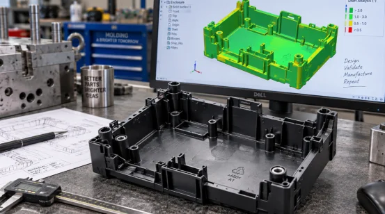
Rapid Prototype Injection Moulding: A Practical Guide for Plastic Part Development
A CAD model can look finished while the moulded part still carries open questions. Will the ribs sink? Will the clips survive assembly? Will the housing warp around a button? Rapid prototype injection moulding answers those questions with real moulded parts made from the planned resin.
The method suits plastic part development that needs functional testing, pilot builds, customer samples, or early sales units. Speed comes from a focused tool scope and engineering work before metal cutting begins.
What Is Rapid Prototype Injection Moulding?
Rapid injection molding uses a quickly manufactured mould to produce repeatable plastic parts. Many teams also call it prototype injection molding or rapid tooling. The process follows the same basic cycle as production moulding: clamp, inject, pack, cool, open, and eject.
How It Differs from a Production Tool
An injection mould prototype commonly uses aluminium, P20, NAK80, or harder inserts in wear areas. Quantity, resin, finish, and tolerance guide the choice. Aluminium may serve a short run. P20 supports welding and design changes, while NAK80 suits polished surfaces.
Production tools may add multiple cavities, hardened steels, hot runners, automated actions, and serviceable wear parts. A rapid tool keeps the build tied to the current test goal.
When Should You Use Rapid Tooling?
Use rapid tooling when printed or machined prototypes cannot answer the next engineering question. Moulded resin behaves differently around weld lines, living hinges, snap fits, bosses, and textured walls.
Functional Validation and Pilot Runs
Use production-grade materials to test stiffness, chemical resistance, heat response, or assembly force. ABS suits tough housings, PC supports impact-resistant or clear parts, PP suits living hinges, and PA handles loaded components. Filled PA and high-temperature grades can wear soft tooling quickly.
Low-volume injection molding covers pilot production and limited releases. Bridge tooling can supply saleable units during a long-life mould build and give buyers measured cycle, scrap, and inspection data.
How Does the Development Process Work?
A useful process starts with part requirements. Share the 3D model, 2D drawing, resin grade, colour, finish, quantity, critical dimensions, and assembly context. Mark sealing faces and cosmetic zones. A vague note such as tight tolerance everywhere raises cost and leaves room for argument.
DFM Before Tooling
Design for manufacturability checks wall thickness, draft, undercuts, ribs, bosses, parting lines, gates, vents, and ejection. The DFM analysis should also identify dimensions that cross the parting line and features that need sliders, lifters, inserts, sleeves, or unscrewing mechanisms.
Wall sections around 1.5 to 2.5 mm suit many common thermoplastics, though the resin supplier’s range and the part function take priority. Keep adjacent walls close in thickness. Thick boss bases cool slowly and can pull a visible sink into the opposite face. Draft helps the part release; texture usually needs more draft than a polished surface.
Flow simulation can test gates, runner balance, weld lines, air traps, pressure, and thermal behaviour. It suits thin walls, long flow paths, multi-cavity tools, and appearance parts. Each finding should lead to an action such as moving a gate or revising a cooling channel.
Tool Build, Trial, and Correction
CNC machining forms most cores and cavities. EDM handles deep slots, sharp internal details, and geometry a cutter cannot reach cleanly. Wire cutting, grinding, fitting, and polishing complete the tool.
T0 checks filling, opening, ejection, and safe operation. The team records short shots, flash, burns, sinks, weld lines, warpage, sticking, and dimension drift. T1 samples should include the agreed resin, process record, dimensional report, and remaining actions. A pretty sample from an unstable cycle is still an unfinished result. Shop floors learn this lesson often.
Which Design Choices Control Part Quality?
Part quality comes from linked decisions. Gate location affects weld lines and packing. Cooling affects cycle time and warpage. Ejection affects drag marks, whitening, and distortion.
Gates, Cooling, Venting, and Ejection
Place the gate where melt can fill the cavity with manageable pressure and pack thick regions. Balanced runners matter in multi-cavity tools because one early-filling cavity can steal pressure from another. Vents at the end of flow paths release trapped air and reduce burns.
Cooling often takes the largest share of the moulding cycle. Channels need even coverage around the core and cavity. Local hot spots keep one area soft while nearby plastic contracts, which can twist a flat housing after ejection. Ejector pins, sleeves, stripper plates, lifters, or air ejection then need enough contact area to move the part without dents.
What Should You Check Before Placing an Order?
Compare quotations by scope. The lowest tooling figure says little when the quote omits resin, trials, inspection, changes, or the expected tool life.
A Practical Purchasing Checklist
Ask each plastic injection mould manufacturer to state the mould material, hardness, cavity count, runner type, tool life, included trials, T1 lead time, dimensional report, maintenance plan, and ownership terms. Confirm press tonnage and shot size. A large projected area needs enough clamp force to control flash.
Review part cost at several quantities. Cold runners suit many short runs, though every shot produces runner material. Hot runners cut waste and may shorten the cycle, while tooling and maintenance cost more. Volume and resin price guide the choice.
Allow time for one correction loop after the first trial. Standard rapid moulds may reach T1 in roughly two to four weeks. Complex unscrewing, insert, or two-material structures can take four to eight weeks. Geometry, steel availability, finish, and inspection scope can move those dates, so a milestone plan is more useful than a single delivery promise.
Turning Prototype Results into a Production Decision
The trial report should connect each defect with an action and an owner. That record turns a rapid tool into a practical production gate.
XINKEY MOULD supports this stage through early DFM, mould-flow review, rapid prototype mould development, trial moulding, and bridge production. Its engineering scope covers sliders, lifters, inserts, threaded cores, hot and cold runners, balanced ejection, and cooling layouts for parts that need more than a straight open-and-close tool. Precision machining includes CNC, EDM, and wire cutting, with machining control reaching the +/-0.01 mm level where the feature and inspection method support it.
The team can carry trial findings into mould corrections and low-volume part production, which keeps design feedback, tooling changes, and process records connected. For a buyer, that continuity makes the T1 review easier to audit and gives the production-tool decision a firmer cost and quality basis.
FAQ
Q1: How Fast Can a Rapid Prototype Mould Produce T1 Samples?
A: A standard tool may reach T1 in about two to four weeks. Slides, unscrewing systems, inserts, two-material structures, special steels, or demanding finishes can extend the schedule to four to eight weeks.
Q2: How Many Parts Can a Rapid Injection Mould Produce?
A: Tool life depends on mould material, resin, pressure, temperature, geometry, and maintenance. Define the required shot count before quoting so the toolmaker can select suitable steel and protect high-wear areas.
Q3: Can You Use the Final Production Resin?
A: Yes, in many projects. Using the intended resin gives better evidence for fit, strength, shrinkage, heat response, and surface quality. Abrasive, corrosive, or high-temperature grades may require steel inserts or a steel tool.
Q4: What Files Should You Send for a Quote?
A: Send a 3D model, a dimensioned 2D drawing, resin grade, colour, finish, quantity, annual forecast, critical tolerances, assembly details, and the required sample date.
Q5: When Should You Move to a Production Mould?
A: Move when the design is stable, trials meet the acceptance criteria, and forecast volume supports a longer-life tool. Use measured cycle time, scrap rate, maintenance needs, and unit cost from the prototype run in that decision.
Our Service
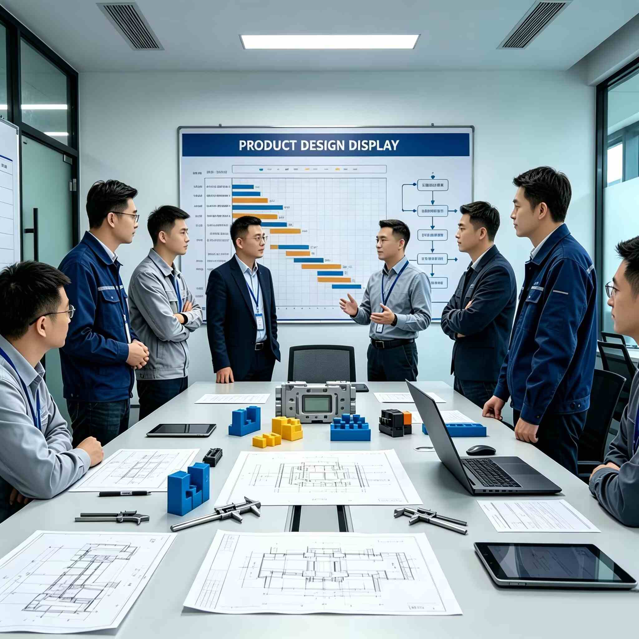
Project Engineering & DFM
We don't just receive your file and start cutting. Before any steel is touched, our engineers review your design to catch the problems that cost you money later. One engineer owns your project from your first message to final shipment.
Learn More
Precision Mold Machining
→CNC Machining (±0.005mm)
→EDM — complex cavities others can't cut
→Wire EDM — intricate profiles, zero distortion
Learn More

Mold Trial & Production
→Trial Mold & First-Shot Review
→Low-Volume Production (100–50,000 pcs)
→Full Dimensional Inspection & QC Report
Learn More

Global Delivery & Logistics Support
From mold completion to finished plastic parts arriving at your warehouse,
we coordinate manufacturing, packaging, customs and transportation under one project management system
Learn More



Contact Us