
Parâmetros do processo de moldagem por injeção: como otimizar a temperatura de fusão, a pressão e o tempo de resfriamento.
Parâmetros do Processo de Moldagem por Injeção: A Verdadeira Chave para a Qualidade das Peças
Ser um ótimo moldador não se resume a memorizar as configurações da máquina. Trata-se de gerenciar a física do processo de moldagem por injeção.
Cada parâmetro — temperatura de fusão, pressão de injeção, compactação e tempo de resfriamento — está interligado. Altere um e os demais serão afetados.
Se você deseja qualidade consistente das peças, menores taxas de refugo e produção estável, precisa entender como essas variáveis essenciais realmente funcionam em conjunto.
1. Temperatura de Fusão: A Base da Moldagem por Injeção
Palavra-chave principal: temperatura de fusão na moldagem por injeção
A temperatura de fusão define como o plástico flui para dentro do molde.
Muito baixa → alta viscosidade
Injeções incompletas
Linhas de solda fracas
Acabamento superficial ruim
Muito alta → degradação do material
Marcas de queimadura
Resistência reduzida
Fragilidade
Melhores Práticas
Comece com a faixa de temperatura recomendada pelo fornecedor e ajuste com base no comportamento da peça.
Uma temperatura de fusão mais alta pode melhorar o fluxo, mas geralmente aumenta o tempo de resfriamento.
2. Velocidade e Pressão de Injeção: O Equilíbrio Crítico
Palavra-chave principal: pressão e velocidade de injeção
A velocidade de injeção determina a rapidez com que a cavidade é preenchida, enquanto a pressão fornece a força para empurrar o material através do sistema.
Velocidade de Injeção
Muito lenta → congelamento prematuro
Muito rápida → turbulência, bolhas de ar, marcas de queimadura
Pressão de Injeção
Muito baixa → preenchimento incompleto
Muito alta → rebarbas, tensão no molde
Informações sobre Otimização
Se sua máquina estiver atingindo os limites de pressão, verifique:
Viscosidade do material
Tamanho e projeto do ponto de injeção
3. Compactação e Retenção: Controlando a Contração
Palavra-chave principal: compactação, pressão, moldagem por injeção
Após o preenchimento de 95% a 98%, o processo entra na fase de compactação.
O plástico encolhe ao esfriar — a compactação compensa isso alimentando a cavidade com material adicional.
Defeitos comuns devido à má embalagem
Marcas de afundamento
Vazios internos
Peso inconsistente da peça
Regra fundamental
A pressão de retenção deve continuar até que o ponto de injeção congele. Após esse ponto, as dimensões da peça ficam fixas.
4. Tempo de resfriamento: o fator oculto de custo
Palavra-chave principal: tempo de resfriamento na moldagem por injeção
O tempo de resfriamento normalmente representa de 60% a 80% do tempo total do ciclo.
Esta etapa determina:
Eficiência do ciclo
Estabilidade dimensional
Risco de empenamento
Erro comum
Reduzir demais a temperatura do resfriador → condensação no molde → defeitos na peça
Otimização inteligente
Aumentar a vazão do fluido refrigerante
Limpar a incrustação dentro dos canais de resfriamento
Usar insertos de alta condutividade térmica
5. Temperatura do molde: Acabamento superficial e Estabilidade
Palavra-chave principal: controle de temperatura do molde
A temperatura do molde impacta diretamente:
Aparência da superfície
Nível de brilho
Visibilidade da linha de solda
Temperatura do molde mais alta
Melhor replicação da superfície
Aparência aprimorada
Redução das linhas de solda
Contraponto
Tempo de resfriamento mais longo
Para materiais semicristalinos (como PA, POM): A temperatura do molde também afeta a cristalinidade, o que influencia a estabilidade dimensional a longo prazo.
Otimização da Moldagem por Injeção: Pense em Sistemas, Não em Configurações
O maior erro na moldagem por injeção é tratar os parâmetros de forma independente.
Na realidade:
Alterar o tempo de resfriamento afeta a contração
Ajustar a compactação afeta a tensão interna
Modificar a temperatura impacta o fluxo e a pressão
� A moldagem por injeção é um sistema de circuito fechado
Melhor prática: Defina sua janela de processo
Assim que encontrar a combinação ideal de parâmetros:
Documente
Padronize
Controle a variação
A inconsistência do processo é a principal causa de:
Refugo
Empenamento
Flutuações de qualidade
Uma oficina disciplinada e orientada por dados sempre terá um desempenho superior àquela que depende da intuição do operador.
� Chamada para ação (CTA)
Se você está enfrentando problemas com defeitos nas peças, tempo de ciclo ou produção instável, geralmente não se trata de um problema com um único parâmetro — é um problema do sistema.
� Precisa de ajuda para otimizar o projeto do seu molde ou o processo de injeção? Visite: www.xinkeymould.com ou entre em contato com nossa equipe de engenharia para uma avaliação profissional.
LEIA MAIS
Manutenção de moldes de injeção: lista de verificação essencial e melhores práticas
Pare de "apagar incêndios": O verdadeiro retorno sobre o investimento da manutenção disciplinada de moldes de injeção
Pense no seu molde de injeção como o coração de alto desempenho da sua fábrica. Quando ele recebe a manutenção adequada, tudo funciona perfeitamente. Quando negligenciado, ele rapidamente se torna um passivo — aumentando as taxas de refugo, causando tempo de inatividade e desencadeando reparos emergenciais dispendiosos nos piores momentos possíveis.
Uma rotina de manutenção disciplinada não se trata apenas de limpar o aço. Trata-se de proteger seu cronograma de produção e prolongar a vida útil de um dos seus ativos mais caros.
A dura realidade da prensa
Os moldes são ferramentas de precisão que operam em condições extremamente severas. Diariamente, eles suportam forças de fechamento enormes e choques térmicos repetidos, às vezes superiores a 300 °C. Ao mesmo tempo, materiais abrasivos — especialmente resinas com carga de vidro — desgastam continuamente as superfícies de aço.
Quando a manutenção é ignorada, os problemas não aparecem gradualmente — eles se intensificam. Pequenos desgastes se transformam em pinos emperrados, deslizadores presos e respiros bloqueados. Quando as aberturas de ventilação entopem, os gases presos causam queimaduras e defeitos, levando a produção a um declínio constante.
Nem mesmo os canais de refrigeração estão imunes. Com o tempo, depósitos minerais restringem o fluxo, reduzindo a eficiência da refrigeração e afetando a qualidade das peças. Comparado ao custo de uma reconstrução completa ou da perda de um cliente, a manutenção preventiva é mínima.
Lista de Verificação Pré-Voo: Hábitos Diários de Produção
Antes de iniciar a produção, reserve alguns minutos para uma inspeção básica — assim como a inspeção pré-voo de um piloto.
Verifique problemas óbvios, como:
Pinos extratores quebrados
Insertos lascados ou danificados
Deslizadores desgastados ou desalinhados
Ignorar esta etapa é arriscado. Detectar pequenos problemas precocemente é muito mais fácil do que lidar com falhas graves durante a produção.
Durante a produção, não observe apenas as peças — observe o processo. Alterações dimensionais inesperadas ou aumento nas taxas de refugo são sinais de alerta precoce. Resolva-os imediatamente antes que se agravem.
As principais verificações diárias incluem:
Saúde Térmica: Verifique o fluxo do fluido refrigerante e a consistência da temperatura. Diferenças anormais entre entrada e saída podem indicar bloqueios ou incrustações.
Limpeza das ferramentas: Limpe as linhas de junção e as superfícies das cavidades regularmente. Evite usar ferramentas de metal em superfícies polidas — pequenos danos podem afetar permanentemente a qualidade do acabamento.
Plano de ação semanal
Manter-se à frente do desgaste requer manutenção consistente e estruturada.
A cada semana:
Limpe e lubrifique todos os componentes móveis (deslizadores, extratores, guias).
Remova detritos e acúmulo de graxa antiga.
Desobstrua os canais de ventilação usando ar comprimido.
Ventilação obstruída leva diretamente a marcas de queimadura e sucata — esta etapa é crucial.
Manutenção mensal e trimestral
Mensalmente (Monitoramento de tendências): Use ferramentas de medição calibradas para acompanhar as dimensões críticas. Identificar desvios graduais ajuda a prevenir falhas inesperadas.
Manutenção Trimestral (Manutenção Profunda):
Desmonte e inspecione o sistema de ejeção.
Verifique o desgaste das superfícies guia.
Limpe e remova a incrustação dos canais de refrigeração.
Substitua quaisquer componentes que apresentem sinais precoces de fadiga.
Revisão Anual
Uma vez por ano, realize uma desmontagem e inspeção completas.
Observe:
Corrosão ou pitting
Degradação da superfície
Fissuras finas causadas por fadiga
Igualmente importante: revise os registros de manutenção. Se o mesmo componente falhar repetidamente, o problema provavelmente está no projeto, e não na manutenção. Nesse caso, a solução real é redesenhar o equipamento.
Erros Graves que Vemos com Muita Frequência
1. Usar o Lubrificante Incorreto: Nem todas as graxas são adequadas para moldes. Produtos incorretos podem danificar o aço ou contaminar as peças. Sempre siga as recomendações do fabricante.
2. Apertar os Parafusos em Excesso: O torque excessivo pode esticar os parafusos e danificar os insertos. Use uma chave dinamométrica e siga as especificações adequadas.
3. Ignorar os Sistemas de Resfriamento: As linhas de resfriamento funcionam como artérias. O acúmulo de incrustações reduz a eficiência, aumenta o tempo de ciclo e cria pontos quentes que afetam a qualidade das peças.
4. Negligenciar a Manutenção Devido à Pressão da Produção: Adiar a manutenção durante produções de alto volume geralmente leva a quebras não planejadas — normalmente no pior momento. A manutenção programada é sempre mais econômica do que reparos emergenciais.
Em resumo: Manutenção é Seguro
A manutenção de moldes de injeção não é um custo — é uma proteção para a estabilidade da sua produção.
Uma ferramenta bem conservada terá um desempenho consistentemente melhor e durará mais do que uma negligenciada. A diferença aparece no tempo de atividade, na qualidade e na lucratividade a longo prazo.
Conselho Final
Crie um cronograma de manutenção claro e atribua responsabilidade por cada tarefa. A responsabilidade é o que mantém os sistemas funcionando.
As empresas que seguem rotinas disciplinadas permanecem produtivas. Aquelas que não seguem acabam reagindo constantemente a problemas.
No final, é simples: ou você controla a manutenção — ou ela controla sua produção.
LEIA MAIS
Entendendo o “Inimigo Invisível”: Por que a Ventilação do Molde é crucial para o Sucesso da Moldagem por Injeção
Introdução
À primeira vista, uma cavidade de molde parece vazia. Na realidade, nunca está.
Cada injeção começa com ar já preso dentro da cavidade — e esse ar precisa ir para algum lugar. Se não puder escapar adequadamente, ele é comprimido rapidamente à medida que o material fundido flui para dentro. O resultado? As temperaturas podem ultrapassar 300 °C em milissegundos.
O que você criou, na prática, é uma câmara de combustão em miniatura dentro do seu molde.
Na linha de produção, a ventilação inadequada costuma ser a culpada silenciosa por marcas de queimadura, defeitos estéticos e problemas inexplicáveis de produção.
Os Altos Riscos da Compressão de Ar
Durante a injeção, o plástico fundido normalmente flui a velocidades de 20 a 200 mm/s. À medida que preenche a cavidade, ele empurra o ar à sua frente.
Esse ar precisa sair por aberturas — geralmente pequenas folgas na linha de junção ou por meio de dispositivos de ventilação específicos.
A física é implacável:
Compressão rápida = aumento rápido da temperatura.
Em casos extremos, o ar aprisionado comporta-se como um pequeno motor a diesel, inflamando e queimando a superfície do plástico.
Essas "queimaduras de gás" não são apenas problemas estéticos. Elas indicam degradação do material em nível molecular, o que pode comprometer a resistência da peça e o desempenho a longo prazo.
Além das queimaduras, o gás aprisionado cria problemas adicionais:
Contrapressão, dificultando o preenchimento
Injeções incompletas, onde as peças não se formam completamente
Estrias de gás ("corte por gás"), onde o fluxo de ar marca a frente de fusão
Como realmente removemos o ar
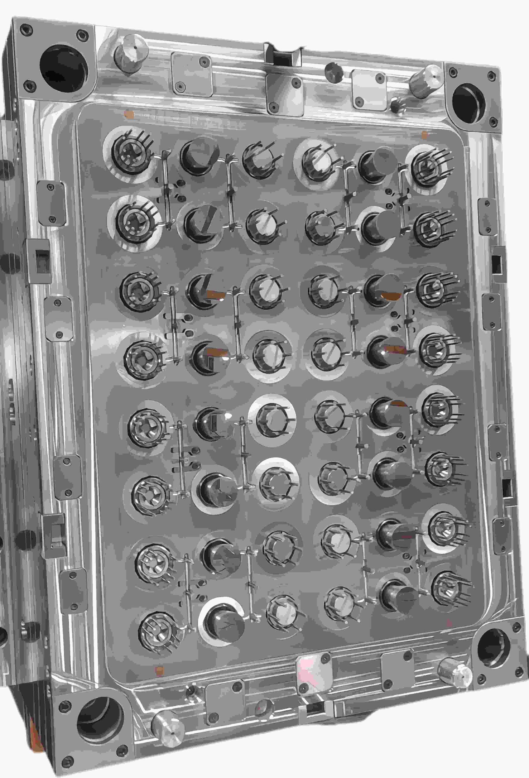
Na prática, o projeto de moldes se resume a criar caminhos de escape confiáveis. Os métodos comuns incluem:
Respiros na linha de partição
Este é o método mais utilizado.
A chave é a precisão:
Profundidade típica do respiro: 0,005–0,02 mm
Muito apertado → o ar fica preso
Muito aberto → ocorre rebarba
Encontrar esse equilíbrio é onde a experiência em fabricação de ferramentas mais importa.
Pinos de Ventilação
Usados em nervuras ou cavidades profundas onde o ar tende a ficar preso.
Diâmetro típico: 2–4 mm
Fornecem caminhos de escape diretos para áreas problemáticas.
Ranhuras e Inserções de Ventilação
Para geometrias complexas, canais de ventilação rasos direcionam o ar para as saídas.
Em casos mais exigentes, inserções de metal poroso (aço sinterizado) permitem a passagem de ar através do próprio material — especialmente úteis em cavidades profundas ou intrincadas.
Ventilação a Vácuo
Usado em aplicações de alta tecnologia, como painéis automotivos.
Em vez de depender da pressão para expulsar o ar, um sistema de vácuo o remove antes mesmo do início da injeção, garantindo condições ideais de preenchimento.
Problemas Comuns na Fábrica
Queimaduras no Final do Preenchimento
Marcas escuras na última área de preenchimento geralmente significam que o ar preso não tem para onde ir.
Injeções Curtas “Fantasmas”
Se uma área não preencher, independentemente da pressão aplicada, provavelmente há uma bolsa de ar atuando como amortecedor. Adicionar uma abertura de ventilação exatamente nesse local geralmente resolve o problema imediatamente.
Equilíbrio entre Rebarba e Ventilação
Folga de ventilação excessiva → rebarba
Folga insuficiente → marcas de queimadura
Encontrar o equilíbrio certo é um desafio constante.
Linhas de Solda Frágeis
Quando as frentes de fluxo se encontram, mas não se unem corretamente, o gás preso costuma ser a causa.
A ventilação adequada no ponto de encontro melhora significativamente a resistência da solda.
Dicas Profissionais para Ferramentas Melhores
Projete a ventilação desde o início
Não trate a ventilação como uma etapa secundária. Identifique os pontos de aprisionamento de ar durante a fase de análise do fluxo do molde.
Use aberturas de ventilação escalonadas
Comece com uma seção rasa para bloquear o plástico e, em seguida, faça a transição para um canal mais profundo para o fluxo de ar.
Adicione múltiplos caminhos de ventilação
Para comprimentos de fluxo longos, coloque aberturas de ventilação a cada 50–100 mm. O ar não deve precisar percorrer todo o comprimento da cavidade.
Conclusão
A ventilação não é um detalhe menor — é um fator essencial para o desempenho do molde.
Um molde bem ventilado:
Preenche-se mais facilmente
Requer menos pressão
Produz peças mais consistentes
Reduz defeitos e tempo de inatividade
Tentar corrigir a ventilação após o endurecimento do molde é caro, demorado e, muitas vezes, frustrante.
Acertar desde o início não se trata apenas de qualidade da peça — trata-se de evitar custos desnecessários e manter a produção funcionando sem problemas.
LEIA MAIS
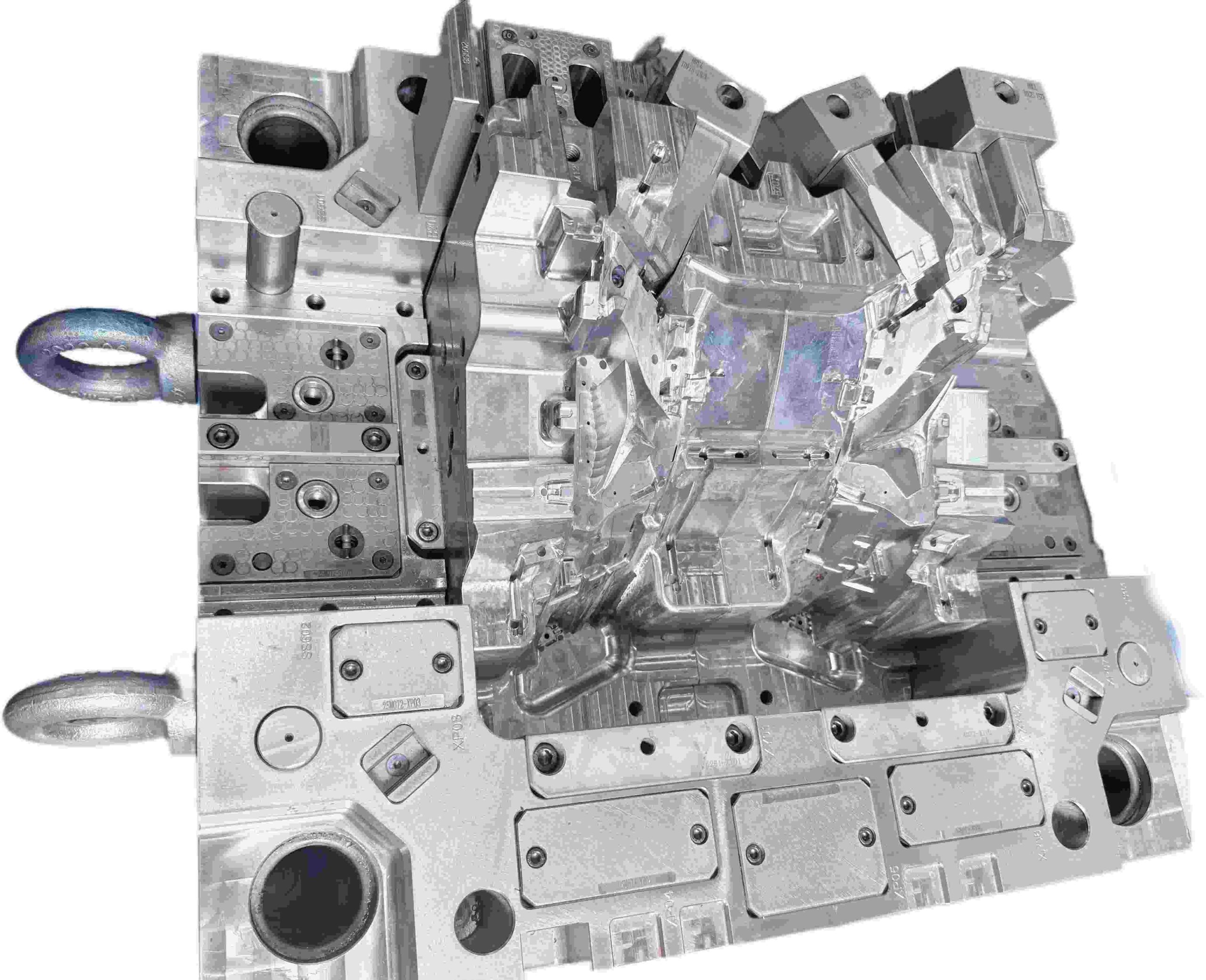
Projeto de deslizadores para moldes de injeção: estrutura, função e melhores práticas
Introdução
Os deslizadores (também chamados de mecanismos laterais ou núcleos laterais) são componentes de moldes que se movem perpendicularmente — ou em um ângulo — à direção de abertura do molde. Eles são usados para formar e liberar rebaixos externos que, de outra forma, impediriam a ejeção reta. Para engenheiros de moldes que trabalham com peças plásticas complexas, entender o projeto de deslizadores é essencial.
O que é um Deslizador de Molde?
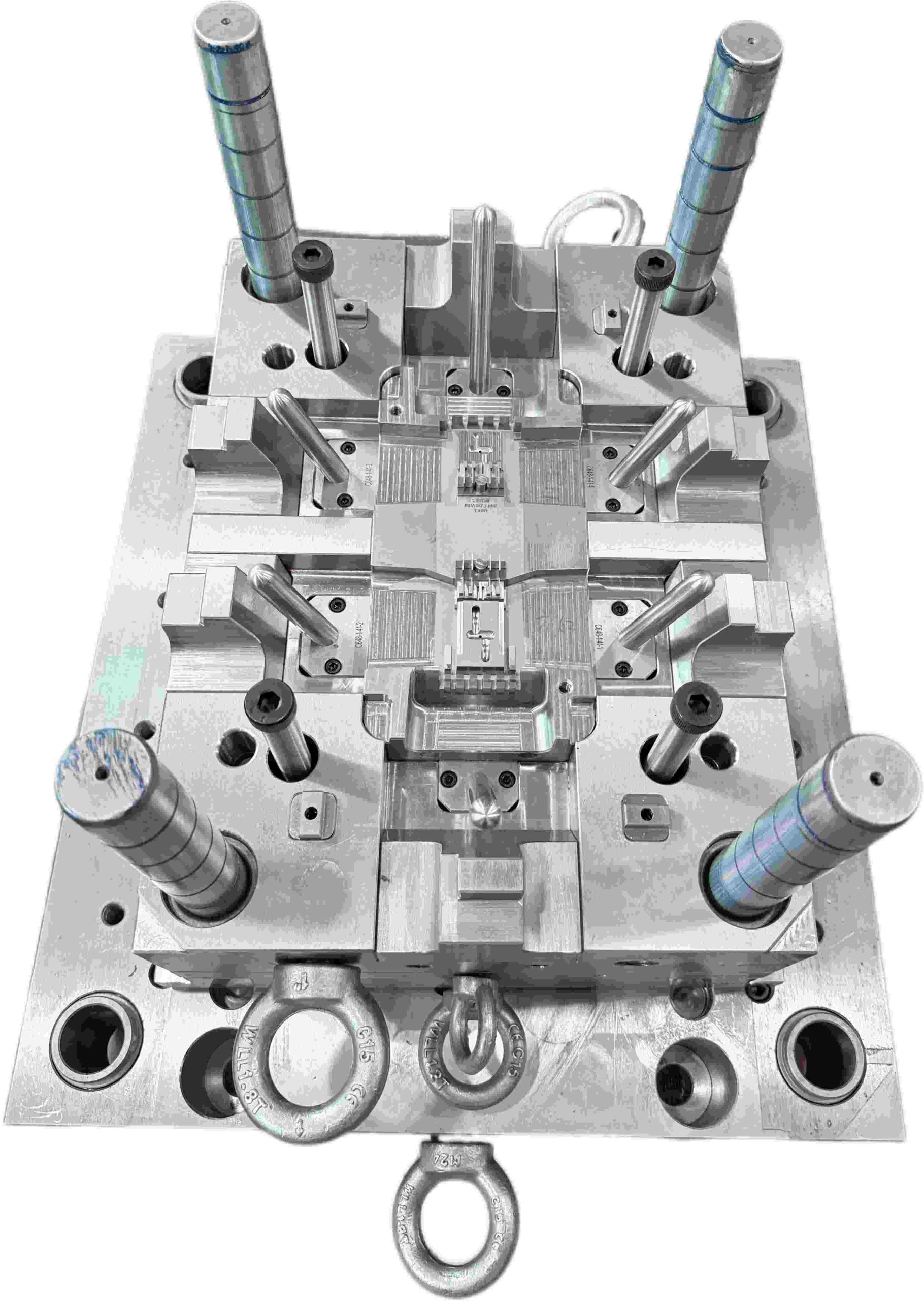
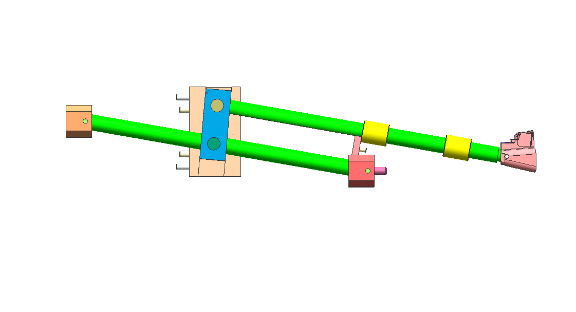
Um deslizador é um componente móvel do molde que se desloca lateralmente durante o curso de abertura para liberar rebaixos externos em uma peça moldada. Ele é normalmente acionado por um pino angular (também chamado de pino de came ou pino de chifre) montado na metade fixa do molde.
À medida que o molde se abre, o pino angular empurra o deslizador para fora. Durante o fechamento do molde, o deslizador é guiado de volta para sua posição de trabalho, pronto para o próximo ciclo.
Para garantir a estabilidade durante a injeção, o deslizador é travado no lugar por um bloco de apoio (cunha de travamento). Sem esse suporte, a alta pressão da cavidade — muitas vezes atingindo centenas de toneladas — pode forçar o deslizador para fora da posição, levando à formação de rebarbas ou variações dimensionais.
Para a construção de moldes padrão, aços-ferramenta pré-endurecidos, como o P20, são comumente usados para o corpo do deslizador. Em aplicações de maior volume, no entanto, o P20 sozinho não é suficiente. Insertos endurecidos ou placas de desgaste são frequentemente adicionados em zonas de alto contato para reduzir o atrito, melhorar a resistência ao desgaste e prolongar significativamente a vida útil da ferramenta.
O deslizador é guiado por guias ou pilares-guia para manter o alinhamento ao longo de seu curso. A distância de curso deve ser pelo menos igual à profundidade do rebaixo mais uma margem de segurança de 2 a 3 mm.
Por que os deslizadores são necessários?
Muitas peças plásticas incluem características como furos laterais, roscas, ganchos, clipes ou geometrias rebaixadas em superfícies externas. Essas características criam rebaixos que impedem a ejeção em linha reta do molde.
Sem um sistema de ação lateral como um deslizador, a peça ficaria mecanicamente travada na cavidade. Qualquer tentativa de ejetá-la diretamente acarretaria o risco de danos à peça, desgaste do molde ou até mesmo a paralisação da produção.
Na prática, o deslizador atua como um mecanismo de liberação obrigatório — ele deve retrair completamente antes que o sistema de ejeção seja ativado. Se o sincronismo estiver incorreto, a peça pode ficar presa, causando danos potenciais e tempo de inatividade não planejado.
Comparados aos levantadores internos, os deslizadores são geralmente mais robustos para rebaixos externos. Eles são acionados pelo movimento de abertura do molde e travados mecanicamente contra a pressão de injeção pelo bloco de apoio, tornando-os adequados para ambientes de produção de alto volume, onde milhões de ciclos são necessários.
Uma vantagem fundamental dos deslizadores é sua capacidade de distribuição de carga. O bloco de apoio e as superfícies guia distribuem as forças de injeção sobre uma área de contato maior, reduzindo a deflexão e o desgaste em comparação com sistemas de elevação mecânicos menores.
Problemas comuns com deslizadores
1. Gripagem e travamento: A gripagem do deslizador ocorre quando as superfícies deslizantes operam com lubrificação insuficiente, levando à aderência de metal e eventual travamento. Isso é especialmente comum em moldes que utilizam materiais abrasivos, como náilon com carga de vidro ou polipropileno com carga mineral. Uma vez iniciado o desgaste por atrito, ele tende a acelerar rapidamente e pode, em última instância, causar o travamento do cursor e a desmontagem do molde para reparo.
2. Carga excessiva no pino angular: Quando o pino angular excede aproximadamente 25°, a carga lateral aumenta significativamente. Isso acelera o desgaste das guias, dos blocos de apoio e do próprio pino angular.
Ângulos mais acentuados também aumentam a força necessária durante a abertura do molde, exercendo estresse adicional em todo o mecanismo ao longo do tempo.
3. Rebarbas nas superfícies de fechamento: Rebarbas na face de fechamento do cursor indicam assentamento inadequado. Causas comuns incluem blocos de apoio desgastados, pré-carga insuficiente ou leve deformação do pino angular.
Se não forem corrigidas precocemente, o acúmulo de rebarbas pode acelerar o desgaste tanto do cursor quanto das superfícies de contato.
4. Desalinhamento de sincronização: A sincronização incorreta do cursor pode causar defeitos graves. Se o cursor se mover antes que a peça seja totalmente liberada, ele pode arrastar a peça lateralmente, resultando em arranhões superficiais, deformação ou distorção dimensional.
Soluções de Design e Melhores Práticas
Mantenha a geometria do pino angular entre 15° e 22° para equilibrar a força e reduzir a carga lateral.
Use ranhuras de lubrificação específicas nas placas de desgaste e assegure-se de que a graxa alcance todas as interfaces deslizantes.
Use materiais autolubrificantes, como bronze AMPCO, buchas Oilite ou insertos de desgaste compostos.
Implemente um sistema de retorno com mola para garantir o assentamento completo do deslizador antes do fechamento do molde.
Projete ângulos de travamento do bloco de calcanhar 2 a 3° mais acentuados que o pino angular para garantir o fechamento seguro sob pressão.
Adicione um sistema de retorno antecipado do ejetor para que os pinos ejetores se retraiam antes do movimento do deslizador, evitando interferências mecânicas.
Dica Profissional
Um deslizador bem projetado deve proporcionar a sensação de um mecanismo de precisão — movimento suave, travamento preciso e consistência da primeira à última injeção.
Um bom desempenho raramente depende de complexidade. Ele se baseia em princípios fundamentais: selecionar os materiais de desgaste corretos, garantir a lubrificação adequada e projetar um sistema de retorno mecânico confiável.Quando esses princípios básicos estão corretos, o molde funciona com intervenção mínima.
No entanto, o deslizador mais econômico costuma ser aquele que você nunca constrói. Sempre avalie se uma pequena alteração no projeto da peça pode eliminar completamente o rebaixo. Simplificar a geometria geralmente leva a custos mais baixos, maior confiabilidade e manutenção mais fácil.
LEIA MAIS
Tempo de ciclo do molde: a alavanca de lucro oculta na moldagem por injeção
Se você já passou algum tempo em uma fábrica de moldagem por injeção, perceberá uma coisa rapidamente: todos falam sobre qualidade, mas o que realmente importa é o tempo.
O tempo de ciclo não é apenas um número na tela da máquina — ele está diretamente ligado ao custo, à produção e, em última análise, à sua margem de lucro. Em muitos projetos, o tempo de ciclo não recebe muita atenção no início. Quando ele se torna uma preocupação, o projeto do molde já está definido e as alterações são caras.
Neste artigo, vamos analisar o que o tempo de ciclo realmente significa na prática, o que tende a atrasá-lo e onde você pode, de forma realista, fazer melhorias — sem comprometer a qualidade da peça.
O que é o tempo de ciclo do molde?
O tempo de ciclo do molde se refere ao tempo total necessário para completar um ciclo completo do processo de moldagem por injeção. Isso inclui:
Fechamento do molde
Injeção (enchimento)
Compactação e retenção
Resfriamento
Abertura do molde
Ejeção da peça
Em termos simples: o tempo de ciclo é basicamente o tempo que leva desde o fechamento de um molde até a próxima injeção.
À primeira vista, 25 segundos em vez de 30 segundos não causam alarme. Mas, na produção contínua, essa diferença se acumula rapidamente. Com o tempo, você acaba com menos ciclos, o que significa diretamente menos produção com os mesmos recursos.
É aí que o tempo de ciclo começa a importar — não no papel, mas no seu resultado final.
O custo da máquina por peça aumenta.
Os custos de mão de obra e energia aumentam.
Os prazos de entrega se estendem.
É por isso que projetistas de moldes experientes não projetam apenas para "peças boas" — eles projetam para ciclos eficientes.
Fatores-chave que afetam o tempo de ciclo do molde
O tempo de ciclo não é controlado por um único parâmetro. É o resultado de múltiplas decisões de projeto e processo.
1. Tempo de resfriamento (o maior fator)
O resfriamento geralmente consome de 60 a 80% do tempo total do ciclo.
O que o influencia:
Espessura da peça
Tipo de material
Temperatura do molde
Projeto do canal de resfriamento
Peças mais espessas retêm o calor por mais tempo. Um projeto de resfriamento inadequado piora a situação.
� Se você deseja ciclos mais rápidos, comece com um resfriamento melhor — não com uma injeção mais rápida.
2. Projeto da Peça
Decisões de projeto tomadas no início podem determinar o tempo de ciclo.
Principais impactos do projeto:
Espessura uniforme da parede → resfriamento mais rápido
Evitar nervuras/saliências espessas → menor concentração de calor
Ângulos de saída adequados → ejeção mais rápida
Projeto ruim = resfriamento mais longo + problemas de ejeção.
3. Seleção de Materiais
Plásticos diferentes se comportam de maneira diferente.
Por exemplo:
PP / PE → resfriamento mais rápido
PC / ABS → resfriamento mais lento
Materiais com carga de fibra de vidro → exigem mais controle
Escolher o material sem considerar o tempo de ciclo é um erro comum.
4. Projeto e Engenharia do Molde
Um molde bem construído pode reduzir drasticamente o tempo de ciclo.
Elementos críticos:
Canais de resfriamento otimizados (resfriamento conformal, se possível)
Posicionamento correto do ponto de injeção
Ventilação eficiente
Sistema de canais balanceado
Um molde mediano "funciona". Um molde bem projetado gera lucro mais rapidamente.
5. Parâmetros da máquina
Mesmo com um molde perfeito, configurações inadequadas da máquina podem atrasar todo o processo.
Parâmetros principais:
Velocidade de injeção
Pressão/tempo de recalque
Configuração do tempo de resfriamento
Velocidade de abertura/fechamento da prensa
O ajuste fino é importante, mas não corrige um projeto ruim.
Maneiras práticas de reduzir o tempo de ciclo do molde
Veja o que realmente funciona em ambientes de produção reais:
Otimize o sistema de resfriamento primeiro
Adicione canais de resfriamento perto de pontos quentes
Use defletores ou borbulhadores, se necessário
Considere o resfriamento conformal para peças complexas
� Isso proporciona o maior retorno sobre o investimento.
Reduza a espessura da parede (quando possível)
Mesmo uma pequena redução pode diminuir significativamente o tempo de resfriamento.
Exemplo: 3,0 mm → 2,5 mm pode reduzir o tempo de resfriamento consideravelmente.
Mas sempre equilibre resistência e funcionalidade.
Melhore a ventilação do molde
Uma melhor ventilação permite:
Preenchimento mais rápido
Redução de marcas de queimadura
Menor pressão de injeção
O que indiretamente reduz o tempo de ciclo.
Use materiais de molde de alta eficiência
Insertos de cobre-berílio (para áreas quentes)
Aços de alta condutividade térmica
Esses materiais ajudam a dissipar o calor mais rapidamente.
Automatize sempre que possível
Remoção robótica de peças
Ejeção mais rápida e consistente
O manuseio manual atrasa os ciclos mais do que as pessoas imaginam.
Erros comuns que aumentam o tempo de ciclo
Sejamos honestos: isso acontece o tempo todo:
Dimensionar a espessura da parede excessivamente "apenas por segurança"
Ignorar o resfriamento durante o projeto do molde
Posicionamento inadequado do ponto de injeção, levando a um preenchimento irregular
Definir um tempo de resfriamento excessivo como margem de segurança
Tentar corrigir problemas de projeto com parâmetros da máquina
Essas decisões corroem silenciosamente suas margens de lucro.
Tempo de Ciclo vs. Qualidade da Peça: Encontrando o Equilíbrio
Reduzir o tempo de ciclo de forma muito agressiva pode ser contraproducente.
Você pode observar:
Empenamento
Marcas de afundamento
Tensão interna
Instabilidade dimensional
O objetivo não é o ciclo mais curto, mas sim o ciclo ideal.
Considerações Finais
O tempo de ciclo do molde é um dos fatores mais subestimados na lucratividade da moldagem por injeção.
Não é apenas um parâmetro de processamento, mas sim o resultado de:
Projeto inteligente da peça
Engenharia cuidadosa do molde
Seleção adequada de materiais
Processamento controlado
Ao considerar o tempo de ciclo desde o início — enquanto a peça e o molde ainda estão sendo projetados — você terá muito mais espaço para otimizar. Depois que as ferramentas estiverem prontas, aprimorá-las se torna muito mais difícil e caro.
Perguntas Frequentes
P: O que é um “P: Qual é o tempo de ciclo ideal na moldagem por injeção? R: Não existe um padrão único. Depende da peça — seu tamanho, geometria e material. Peças simples e de paredes finas podem ser produzidas bem rápido, geralmente em menos de 20 segundos. Peças maiores ou mais espessas geralmente precisam de mais tempo, às vezes 40 segundos ou mais.
P: O que mais afeta o tempo de resfriamento? R: Na maioria das vezes, é a espessura da parede e o layout de resfriamento dentro do molde. Áreas mais espessas levam mais tempo para liberar calor e, se os canais de resfriamento não estiverem bem posicionados, o atraso se torna ainda mais evidente.
P: Por que meu tempo de ciclo é muito longo? R: As causas comuns incluem peças espessas, projeto de resfriamento inadequado, configurações conservadoras da máquina ou layout ineficiente do molde.
LEIA MAIS
Por que os rebaixos internos são um problema sério na moldagem por injeção
Sejamos honestos: rebaixos internos são um pesadelo para projetistas de moldes. Ao contrário de recursos externos, eles não podem ser resolvidos com deslizadores padrão.
Se a geometria não for projetada corretamente, as consequências são graves:
Peças presas permanentemente no núcleo
Danos ou arranhões na superfície
Quebra da haste do extrator
Paradas de produção dispendiosas
Ao lidar com clipes ou ressaltos internos, o extrator de molde se torna a solução mecânica mais confiável.
Como funciona um extrator de molde: o princípio do "deslocamento lateral"
Um extrator de molde não se move como um deslizador tradicional. Em vez disso, ele é acionado pelo sistema de ejeção.
Durante o ciclo de ejeção:
O extrator se move para cima com a placa ejetora
Ao mesmo tempo, ele segue uma trajetória angulada
Isso cria um movimento combinado vertical e lateral
Esse movimento lateral — frequentemente chamado de "deslocamento lateral" — é o que libera o rebaixo.
Regra de projeto fundamental
Sempre permita pelo menos 2 mm de curso extra além da profundidade do rebaixo.
Qualquer valor inferior a isso aumenta o risco de:
Marcas de arrasto
Arranhões na superfície
Liberação incompleta
O erro mais comum: Ângulo incorreto do elevador
Um dos maiores erros de projeto é definir um ângulo de elevador muito acentuado para economizar espaço.
Ângulo de elevador recomendado
Faixa ideal: 5° – 11°
Zona de risco
Acima de 15°: Alto risco de travamento e falha
Em ângulos mais acentuados:
A força lateral aumenta significativamente
O movimento vertical fica restrito
O elevador pode travar ou a haste pode dobrar
Quando ângulos acentuados são inevitáveis
Se o seu projeto exigir um ângulo maior, considere:
Base articulada do elevador
Elevador com ranhura em T
Esses recursos ajudam a reduzir a tensão na haste do elevador e melhoram a durabilidade.
Seleção de material: Prevenir desgaste e gripagem
Os sistemas de elevador operam sob:
Alta pressão
Alta temperatura
Contato contínuo metal-metal
Escolher o material errado pode levar à gripagem, onde as superfícies se fundem e falham. Materiais Recomendados
Aço ferramenta H13
Aço pré-endurecido 718H
Diretrizes de Dureza
Meta: 50–54 HRC
Mantenha o tucho ligeiramente mais duro que o núcleo
Opção de Alto Desempenho
Para ciclos de produção mais rápidos:
Use insertos de cobre-berílio
Benefícios:
Dissipação de calor mais rápida
Tempo de resfriamento reduzido
Maior eficiência de produção
3 Dicas de Especialistas para um Projeto de Tucho à Prova de Falhas
1. Adicione uma Guia de Cauda
Sempre apoie a extremidade inferior da haste do tucho com um bloco guia.
Sem suporte:
A haste vibra
A vibração leva à formação de rebarbas e desgaste
2. Use Canais de Lubrificação
O atrito é o inimigo de qualquer componente móvel.
Boa prática:
Adicione ranhuras de lubrificação às superfícies deslizantes
Exceção:
Moldes médicos → use revestimento DLC em vez de óleo
3. Controle o ajuste da linha de partição (LP)
A superfície de fechamento do extrator deve se encaixar perfeitamente no núcleo.
Mesmo uma folga de 0,01 mm pode causar:
Linhas de referência visíveis
Qualidade superficial ruim
Extrator vs. Deslizante: Qual usar?
A escolha entre um extrator e um deslizante depende inteiramente da localização do rebaixo.
Use um deslizante quando:
O rebaixo for externo
Há espaço suficiente para movimento lateral
Use um extrator quando:
O rebaixo for interno
O espaço for limitado
Sistemas hidráulicos não forem práticos
Considerações finais
Um extrator de molde é uma das soluções mais eficientes para rebaixos internos — mas somente quando projetado corretamente.
Controlando:
Ângulo
Folga de deslocamento
Seleção de material
Suporte estrutural
Você pode transformar um recurso de alto risco em um mecanismo confiável e repetível que mantém sua linha de produção funcionando sem problemas.
Precisa de ajuda para otimizar o projeto do seu molde ou resolver problemas complexos de rebaixos? Visite www.xinkeymould.com para obter suporte especializado e melhorar o desempenho das suas ferramentas.
LEIA MAIS


