
معايير عملية التشكيل بالحقن: كيفية تحسين درجة حرارة المصهور والضغط ووقت التبريد
معايير عملية قولبة الحقن: المفتاح الحقيقي لجودة المنتج
لا يقتصر التميز في قولبة الحقن على حفظ إعدادات الماكينة، بل يتعداه إلى فهم فيزياء عملية قولبة الحقن.
جميع المعايير - درجة حرارة الانصهار، وضغط الحقن، والتعبئة، ووقت التبريد - مترابطة. تغيير أحدها سيؤدي إلى تغيير البقية تبعًا لذلك.
للحصول على جودة منتج ثابتة، وتقليل نسبة الخردة، وضمان إنتاج مستقر، عليك فهم كيفية عمل هذه المتغيرات الأساسية معًا.
1. درجة حرارة الانصهار: أساس قولبة الحقن
الكلمة المفتاحية: درجة حرارة الانصهار في قولبة الحقن
تحدد درجة حرارة الانصهار كيفية تدفق البلاستيك إلى القالب.
انخفاضها الشديد ← لزوجة عالية
حقن غير مكتمل
خطوط لحام ضعيفة
سطح غير مصقول
ارتفاعها الشديد ← تدهور المادة
علامات احتراق
انخفاض المتانة
هشاشة
أفضل الممارسات
ابدأ بنطاق درجة الحرارة الموصى به من قبل المورد، ثم اضبطه بدقة بناءً على سلوك المنتج.
يمكن أن تؤدي درجة حرارة انصهار أعلى إلى تحسين التدفق، ولكنها غالبًا ما تزيد من وقت التبريد.
٢. سرعة الحقن والضغط: التوازن الدقيق
الكلمة المفتاحية الرئيسية: ضغط وسرعة الحقن
تحدد سرعة الحقن مدى سرعة امتلاء التجويف، بينما يوفر الضغط القوة اللازمة لدفع المادة عبر النظام.
سرعة الحقن
بطيئة جدًا ← تجمد مبكر
سريعة جدًا ← اضطراب، انحباس هواء، علامات احتراق
ضغط الحقن
منخفض جدًا ← امتلاء غير كامل
مرتفع جدًا ← وميض، إجهاد القالب
نصائح للتحسين
إذا كانت آلتك تصل إلى حدود الضغط، فتحقق مما يلي:
لزوجة المادة
حجم البوابة وتصميمها
٣. التعبئة والتثبيت: التحكم في الانكماش
الكلمة المفتاحية الرئيسية: ضغط التعبئة في قولبة الحقن
بعد امتلاء ٩٥٪–٩٨٪، تدخل العملية مرحلة التعبئة.
ينكمش البلاستيك أثناء تبريده، وتعوض التعبئة هذا الانكماش عن طريق تغذية التجويف بمادة إضافية.
... العيوب الشائعة الناتجة عن سوء التعبئة
علامات الانكماش
فراغات داخلية
وزن غير متجانس للقطعة
قاعدة أساسية
يجب الاستمرار في الضغط حتى تتجمد البوابة. بعد ذلك، تُثبّت أبعاد القطعة.
4. وقت التبريد: عامل التكلفة الخفي
الكلمة المفتاحية الرئيسية: وقت تبريد قولبة الحقن
يمثل وقت التبريد عادةً من 60% إلى 80% من إجمالي وقت الدورة.
تحدد هذه المرحلة ما يلي:
كفاءة الدورة
ثبات الأبعاد
خطر التشوّه
خطأ شائع
خفض درجة حرارة المبرد بشكل مفرط ← تكثف على القالب ← عيوب في القطعة
تحسين ذكي
تحسين معدل تدفق سائل التبريد
تنظيف الترسبات داخل قنوات التبريد
استخدام حشوات ذات موصلية حرارية عالية
5. درجة حرارة القالب: تشطيب السطح الاستقرار
الكلمة المفتاحية الأساسية: التحكم في درجة حرارة القالب
تؤثر درجة حرارة القالب بشكل مباشر على:
مظهر السطح
مستوى اللمعان
وضوح خطوط اللحام
ارتفاع درجة حرارة القالب
تحسين دقة استنساخ السطح
تحسين المظهر
تقليل خطوط اللحام
المفاضلة
زيادة وقت التبريد
بالنسبة للمواد شبه البلورية (مثل PA وPOM): تؤثر درجة حرارة القالب أيضًا على درجة التبلور، مما يؤثر على استقرار الأبعاد على المدى الطويل.
تحسين عملية قولبة الحقن: التفكير في الأنظمة، وليس الإعدادات
أكبر خطأ في قولبة الحقن هو التعامل مع المعايير بشكل منفصل.
في الواقع:
يؤثر تغيير وقت التبريد على الانكماش.
يؤثر تعديل التعبئة على الإجهاد الداخلي.
يؤثر تغيير درجة الحرارة على التدفق والضغط.
� عملية قولبة الحقن نظام مغلق.
أفضل الممارسات: حدد نطاق العملية الأمثل.
بمجرد إيجاد توليفة المعلمات المثلى:
وثّقها. وحّدها. وتحكّم في التباين.
عدم اتساق العملية هو السبب الرئيسي لـ:
الخردة. التشوّه. تقلبات الجودة.
الورشة المنظمة التي تعتمد على البيانات ستتفوق دائمًا على تلك التي تعتمد على خبرة المشغل.
� دعوة للعمل:
إذا كنت تعاني من عيوب في القطع، أو وقت دورة طويل، أو إنتاج غير مستقر، فغالبًا لا تكون المشكلة في معلمة واحدة، بل في النظام ككل.
إذا كنت تواجه صعوبة في التعامل مع عيوب القطع، أو وقت الدورة، أو عدم استقرار الإنتاج، فغالبًا لا تكون المشكلة في معلمة واحدة، بل في النظام ككل. � هل تحتاج إلى مساعدة في تحسين تصميم القالب أو عملية الحقن؟ تفضل بزيارة: www.xinkeymould.com أو اتصل بفريقنا الهندسي للحصول على مراجعة احترافية.
اقرأ المزيد
صيانة قوالب الحقن: قائمة التحقق الأساسية وأفضل الممارسات
توقف عن "إطفاء الحرائق": العائد الحقيقي للاستثمار في الصيانة الدورية لقوالب الحقن
تخيل قالب الحقن كقلب مصنعك النابض عالي الأداء. عند صيانته بشكل صحيح، يسير كل شيء بسلاسة. أما عند إهماله، فإنه سرعان ما يتحول إلى عبء، مما يزيد من معدلات الخردة، ويتسبب في توقف الإنتاج، ويؤدي إلى إصلاحات طارئة مكلفة في أسوأ الأوقات.
لا تقتصر الصيانة الدورية على تنظيف الفولاذ فحسب، بل تتعلق بحماية جدول الإنتاج وإطالة عمر أحد أغلى أصولك.
الواقع القاسي للمكبس
القوالب أدوات دقيقة تعمل في ظروف قاسية للغاية. فهي تتعرض يوميًا لقوى ضغط هائلة وصدمات حرارية متكررة، تتجاوز أحيانًا 300 درجة مئوية. في الوقت نفسه، تعمل المواد الكاشطة، وخاصة الراتنجات المملوءة بالألياف الزجاجية، على تآكل أسطح الفولاذ باستمرار.
عند إهمال الصيانة، لا تظهر المشاكل تدريجيًا، بل تتفاقم. يتحول التآكل الطفيف إلى تآكل في المسامير، وتعطل في المنزلقات، وانسداد في فتحات التهوية. وعندما تنسد هذه الفتحات، تتسبب الغازات المحتبسة في حدوث حروق وعيوب، مما يؤدي إلى انخفاض حاد في الإنتاج.
حتى قنوات التبريد ليست بمنأى عن ذلك. فمع مرور الوقت، تُعيق الترسبات المعدنية تدفق الهواء، مما يقلل من كفاءة التبريد ويؤثر على جودة القطع. وبالمقارنة بتكلفة إعادة بناء كاملة أو خسارة عميل، فإن الصيانة الوقائية تُعدّ ضئيلة.
قائمة فحص ما قبل التشغيل: عادات الإنتاج اليومية
قبل بدء الإنتاج، خصص بضع دقائق لإجراء فحص أساسي - تمامًا كما يفعل الطيار عند فحصه قبل الإقلاع.
تحقق من وجود مشاكل واضحة مثل:
مسامير طرد مكسورة
حشوات متشققة أو تالفة
منزلقات مهترئة أو غير محاذية
يُعدّ تخطي هذه الخطوة مخاطرة. فاكتشاف المشاكل الصغيرة مبكرًا أسهل بكثير من التعامل مع الأعطال الكبيرة أثناء الإنتاج.
أثناء التشغيل، لا تكتفِ بمراقبة القطع فقط، بل راقب العملية برمتها. فالتغيرات غير المتوقعة في الأبعاد أو ارتفاع معدلات الخردة هي مؤشرات إنذار مبكر. عالجها فورًا قبل أن تتفاقم.
أثناء التشغيل، لا تكتفِ بمراقبة القطع فقط، بل راقب العملية برمتها. فالتغيرات غير المتوقعة في الأبعاد أو ارتفاع معدلات الخردة هي علامات إنذار مبكرة. عالجها فورًا قبل أن تتفاقم.
تشمل الفحوصات اليومية الرئيسية ما يلي:
السلامة الحرارية: التحقق من تدفق سائل التبريد وثبات درجة حرارته. قد تشير الاختلافات غير الطبيعية بين المدخل والمخرج إلى وجود انسدادات أو ترسبات.
نظافة الأدوات: تنظيف خطوط الفصل وأسطح التجويف بانتظام. تجنب استخدام الأدوات المعدنية على الأسطح المصقولة، فقد يؤثر التلف الطفيف بشكل دائم على جودة التشطيب.
خطة العمل الأسبوعية
يتطلب الحفاظ على الأداء الأمثل صيانة دورية ومنظمة.
كل أسبوع:
تنظيف وتزييت جميع الأجزاء المتحركة (المنزلقات، الرافعات، المثبتات).
إزالة الحطام وتراكم الشحوم القديمة.
تنظيف قنوات التهوية باستخدام الهواء المضغوط.
تؤدي قنوات التهوية المسدودة مباشرةً إلى علامات احتراق وتلف، وهذه الخطوة بالغة الأهمية.
الصيانة الشهرية والربع سنوية
الصيانة الشهرية (مراقبة الاتجاهات): استخدام أدوات قياس معايرة لتتبع الأبعاد الحرجة. يساعد تحديد الانحراف التدريجي على منع الأعطال غير المتوقعة.
الصيانة الدورية (الصيانة الشاملة):
فك نظام الإخراج وفحصه.
فحص تآكل أسطح التوجيه.
تنظيف قنوات التبريد وإزالة الترسبات الكلسية منها.
استبدال أي مكونات تظهر عليها علامات التلف المبكرة.
الصيانة السنوية الشاملة: قم بتفكيك النظام وفحصه بالكامل مرة واحدة سنويًا.
ابحث عن:
التآكل أو التنقر.
تدهور السطح.
التشققات الدقيقة الناتجة عن التلف.
من المهم أيضًا مراجعة سجلات الصيانة. إذا تعطل نفس المكون بشكل متكرر، فمن المرجح أن المشكلة تكمن في التصميم، وليس في الصيانة. في هذه الحالة، يكون إعادة التصميم هو الحل الأمثل.
أخطاء شائعة تُسبب تلف الأدوات:
1. استخدام مواد التشحيم الخاطئة: ليست جميع أنواع الشحوم مناسبة للقوالب. قد تتسبب المنتجات غير المناسبة في تلف الفولاذ أو تلوث الأجزاء. اتبع دائمًا توصيات الشركة المصنعة.
2. الإفراط في شد البراغي: قد يؤدي عزم الدوران الزائد إلى تمدد البراغي وتلف الحشوات. استخدم مفتاح عزم الدوران واتبع المواصفات الصحيحة.
3. إهمال أنظمة التبريد: تعمل خطوط التبريد كالشرايين. يؤدي تراكم الترسبات إلى انخفاض الكفاءة، وزيادة وقت الدورة، وتكوين بؤر ساخنة تؤثر على جودة المنتج.
4. إهمال الصيانة بسبب ضغط الإنتاج: غالبًا ما يؤدي تأخير الصيانة أثناء عمليات الإنتاج بكميات كبيرة إلى أعطال غير مخطط لها، وعادةً ما تحدث في أسوأ الأوقات. الصيانة الدورية دائمًا أكثر فعالية من حيث التكلفة من الإصلاحات الطارئة.
الخلاصة: الصيانة تأمين
صيانة قوالب الحقن ليست تكلفة، بل هي حماية لاستقرار الإنتاج.
الأداة التي تتم صيانتها جيدًا تتفوق باستمرار على الأداة المهملة وتدوم لفترة أطول. يظهر الفرق في وقت التشغيل والجودة والربحية على المدى الطويل.
نصيحة أخيرة: ضع جدول صيانة واضحًا وحدد مسؤولية كل مهمة. المساءلة هي ما يحافظ على استمرارية عمل الأنظمة.
الورش التي تتبع إجراءات منضبطة تحافظ على إنتاجيتها. أما تلك التي لا تتبعها، فتجد نفسها دائمًا في حالة رد فعل للمشاكل.
في النهاية، الأمر بسيط: إما أن تتحكم في الصيانة، أو تتحكم هي في إنتاجك.
اقرأ المزيد
فهم "العدو الخفي": لماذا يُعدّ تهوية القوالب عاملاً حاسماً في نجاح أو فشل عملية قولبة الحقن
مقدمة
للوهلة الأولى، يبدو تجويف القالب فارغًا. لكن في الواقع، لا يكون كذلك أبدًا.
تبدأ كل عملية حقن بهواء محصور داخل التجويف، وهذا الهواء لا بد أن يجد منفذًا. إذا لم يتمكن من الخروج بشكل صحيح، فإنه ينضغط بسرعة مع تدفق المصهور. والنتيجة؟ قد ترتفع درجات الحرارة إلى أكثر من 300 درجة مئوية في أجزاء من الثانية.
ما أنشأته فعليًا هو غرفة احتراق مصغرة داخل القالب.
في ورشة الإنتاج، غالبًا ما يكون سوء التهوية هو السبب الخفي وراء علامات الحروق، والعيوب التجميلية، ومشاكل الإنتاج غير المبررة.
أهمية ضغط الهواء
أثناء الحقن، يتدفق البلاستيك المنصهر عادةً بسرعة تتراوح بين 20 و200 ملم/ثانية. وعندما يملأ التجويف، يدفع الهواء أمامه.
يجب أن يخرج هذا الهواء عبر فتحات التهوية، والتي عادةً ما تكون فتحات صغيرة عند خط الفصل أو عبر فتحات تهوية مخصصة.
قوانين الفيزياء لا ترحم:
الضغط السريع = ارتفاع سريع في درجة الحرارة.
في الحالات القصوى، يتصرف الهواء المحبوس كمحرك ديزل مصغر، فيُشعل سطح البلاستيك ويحرقه.
لا تقتصر هذه "الحروق الغازية" على كونها مشاكل تجميلية فحسب، بل تشير إلى تدهور المادة على المستوى الجزيئي، مما قد يُضعف قوة القطعة وأداءها على المدى الطويل.
إلى جانب الحروق، يُسبب الغاز المحبوس مشاكل إضافية:
ضغط عكسي، مما يُصعّب عملية التعبئة
حقن غير مكتمل، حيث لا تتشكل القطع بشكل كامل
خطوط غازية ("قطع غازي")، حيث يُحدد تدفق الهواء جبهة الانصهار
كيفية إخراج الهواء عمليًا
في تصميم القوالب، يعتمد التهوية على إنشاء مسارات خروج موثوقة. تشمل الطرق الشائعة ما يلي:
فتحات خط الفصل
هذه هي الطريقة الأكثر استخدامًا.
يكمن السر في الدقة:
عمق الفتحة النموذجي: 0.005-0.02 مم
ضيق جدًا ← يُحبس الهواء
واسع جدًا ← يحدث وميض
يُعدّ إيجاد هذا التوازن هو ما تُبرزه خبرة صناعة الأدوات.
دبابيس التهوية
تُستخدم في التجاويف أو الجيوب العميقة حيث يميل الهواء إلى الانحباس.
القطر النموذجي: ٢-٤ مم
توفر مسارات خروج مباشرة من المناطق التي بها مشاكل.
أخاديد وحشوات التهوية
في الأشكال الهندسية المعقدة، توجه قنوات التهوية الضحلة الهواء نحو المخارج.
في الحالات الأكثر تطلبًا، تسمح الحشوات المعدنية المسامية (الفولاذ المُلبّد) بمرور الهواء عبر المادة نفسها، وهو أمر مفيد بشكل خاص في التجاويف العميقة أو المعقدة.
التهوية بالشفط
تُستخدم في التطبيقات المتطورة مثل ألواح السيارات.
بدلاً من الاعتماد على الضغط لدفع الهواء للخارج، يقوم نظام الشفط بإزالته قبل بدء عملية الحقن، مما يضمن ظروف تعبئة مثالية.
مشاكل شائعة في المصانع
حروق نهاية التعبئة
عادةً ما تعني العلامات الداكنة في منطقة التعبئة الأخيرة أن الهواء المحبوس لا يجد منفذًا.
حقن ناقصة "وهمية"
إذا لم يتم تعبئة جزء ما مهما زاد الضغط المُطبق، فمن المحتمل أنك تتعامل مع جيب هوائي يعمل كوسادة. إضافة فتحة تهوية في ذلك الموقع تحديدًا غالبًا ما يحل المشكلة فورًا.
موازنة بين الزوائد والتهوية
زيادة مساحة التهوية ← زوائد
نقصها ← علامات احتراق
يُعدّ تحقيق التوازن الأمثل تحديًا مستمرًا.
ضعف خطوط اللحام
عندما تلتقي جبهات التدفق ولكنها لا تلتصق جيدًا، يكون الغاز المحتبس هو السبب غالبًا.
تُحسّن التهوية المناسبة عند نقطة الالتقاء قوة اللحام بشكل ملحوظ.
نصائح احترافية لأدوات أفضل
صمم التهوية مبكرًا
لا تتعامل مع التهوية كخطوة ثانوية. حدد مصائد الهواء خلال مرحلة تحليل تدفق القالب.
استخدم فتحات تهوية متدرجة
ابدأ بجزء ضحل لحجب البلاستيك، ثم انتقل إلى قناة أعمق لتدفق الهواء.
أضف مسارات تهوية متعددة
في أطوال التدفق الطويلة، ضع فتحات تهوية كل 50-100 مم. لا ينبغي أن يمر الهواء بطول التجويف بالكامل.
الخلاصة
التهوية ليست تفصيلًا ثانويًا، بل هي عامل أساسي في أداء القالب.
قالب جيد التهوية:
يُملأ بسهولة أكبر
يتطلب ضغطًا أقل
ينتج قطعًا أكثر اتساقًا
يقلل العيوب ووقت التوقف
محاولة إصلاح التهوية بعد تصلب القالب مكلفة وبطيئة ومحبطة في كثير من الأحيان.
إنّ إتقان العملية من البداية لا يقتصر على جودة القطع فحسب، بل يتعلق أيضًا بتجنب التكاليف غير الضرورية وضمان استمرار الإنتاج بسلاسة.
اقرأ المزيد
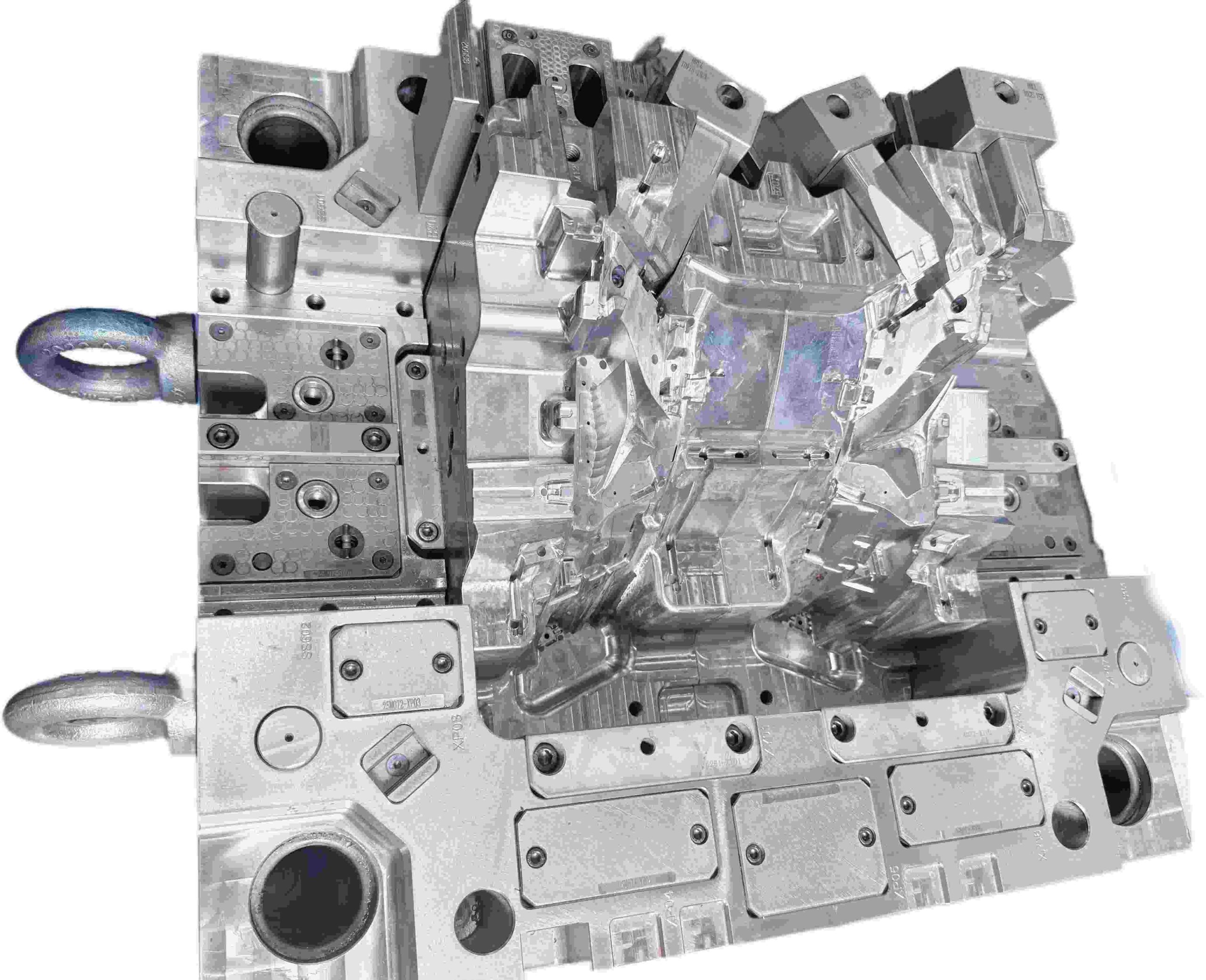
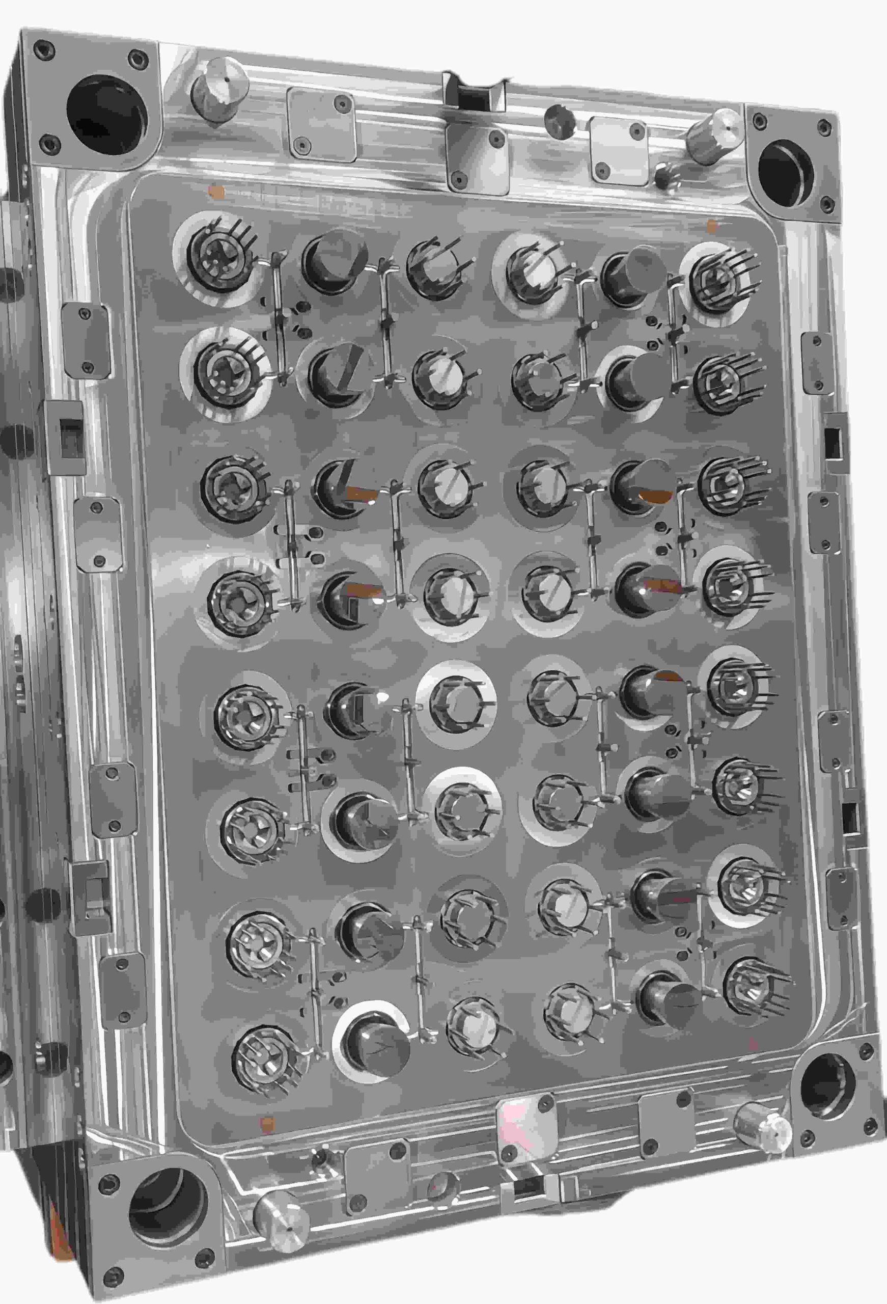
تصميم منزلقات قوالب الحقن: الهيكل والوظيفة وأفضل الممارسات
مقدمة
المنزلقات (وتُسمى أيضًا الأجزاء الجانبية أو النوى الجانبية) هي مكونات قالب تتحرك بشكل عمودي - أو بزاوية - على اتجاه فتح القالب. تُستخدم لتشكيل وفك التجاويف الخارجية التي قد تمنع الإخراج المستقيم. بالنسبة لمهندسي القوالب الذين يعملون على أجزاء بلاستيكية معقدة، يُعد فهم تصميم المنزلقات أمرًا أساسيًا.
ما هو منزلق القالب؟
المنزلق هو مكون قالب متحرك يتحرك جانبيًا أثناء شوط الفتح لتحرير التجاويف الخارجية على الجزء المصبوب. عادةً ما يتم تحريكه بواسطة دبوس زاوية (يُسمى أيضًا دبوس الكامة أو دبوس القرن) مثبت على النصف الثابت من القالب.
عند فتح القالب، يدفع دبوس الزاوية المنزلق للخارج. أثناء إغلاق القالب، يُعاد توجيه المنزلق إلى موضع التشغيل، جاهزًا للدورة التالية.
لضمان الاستقرار أثناء الحقن، يُثبّت المنزلق في مكانه بواسطة كتلة تثبيت (وتد قفل). بدون هذا الدعم، يمكن أن يؤدي ضغط التجويف العالي - الذي غالبًا ما يصل إلى مئات الأطنان - إلى إخراج المنزلق من موضعه، مما يؤدي إلى ظهور زوائد أو اختلافات في الأبعاد.
ما هو منزلق القالب؟ في صناعة القوالب القياسية، تُستخدم عادةً أنواع من الفولاذ المُقسّى مسبقًا، مثل P20، لجسم المنزلق. ولكن في التطبيقات ذات الإنتاج الضخم، لا يكفي P20 وحده. غالبًا ما تُضاف حشوات مُقسّاة أو صفائح مقاومة للتآكل في مناطق التلامس العالي لتقليل الاحتكاك، وتحسين مقاومة التآكل، وإطالة عمر القالب بشكل ملحوظ.
يُوجّه المنزلق بواسطة عوارض أو أعمدة توجيه للحفاظ على استقامته طوال مساره. يجب أن تكون مسافة الحركة مساوية على الأقل لعمق القطع السفلي، بالإضافة إلى هامش أمان يتراوح بين 2 و3 مم.
لماذا تُعدّ المنزلقات ضرورية؟
تتضمن العديد من القطع البلاستيكية ميزات مثل الثقوب الجانبية، والخيوط، والخطافات، والمشابك، أو التجاويف على الأسطح الخارجية. تُنشئ هذه الميزات تجاويف سفلية تمنع خروج القطعة من القالب بشكل مستقيم.
بدون نظام حركة جانبية مثل المنزلق، ستُصبح القطعة عالقة ميكانيكيًا في التجويف. أي محاولة لإخراجها مباشرةً قد تُعرّض القطعة للتلف، أو تآكل القالب، أو حتى توقف الإنتاج.
بدون نظام حركة جانبية مثل المنزلق، ستُصبح القطعة عالقة ميكانيكيًا في التجويف. أي محاولة لإخراجها مباشرةً قد تُعرّض القطعة للتلف، أو تآكل القالب، أو حتى توقف الإنتاج.
عمليًا، يعمل المنزلق كآلية تحرير ضرورية، إذ يجب أن ينكمش بالكامل قبل تفعيل نظام الإخراج. في حال عدم دقة التوقيت، قد تبقى القطعة عالقة، مما قد يؤدي إلى تلفها وتوقفها عن العمل بشكل غير مخطط له.
مقارنةً بالرافعات الداخلية، تتميز المنزلقات عمومًا بمتانتها العالية في عمليات التشكيل الخارجي. فهي تعمل بحركة فتح القالب وتُقفل ميكانيكيًا ضد ضغط الحقن بواسطة كتلة الكعب، مما يجعلها مناسبة لبيئات الإنتاج ذات الأحجام الكبيرة التي تتطلب ملايين الدورات.
من أهم مزايا المنزلقات قدرتها على توزيع الحمل. إذ تعمل كتلة الكعب والأسطح الموجهة على توزيع قوى الحقن على مساحة تلامس أكبر، مما يقلل الانحراف والتآكل مقارنةً بأنظمة الرفع الميكانيكية الأصغر.
مشاكل المنزلقات الشائعة
1. التآكل والالتصاق: يحدث تآكل المنزلق عندما تعمل الأسطح المنزلقة بتشحيم غير كافٍ، مما يؤدي إلى تراكم المعدن وتوقفها في النهاية. وهذا شائع بشكل خاص في القوالب التي تستخدم مواد كاشطة مثل النايلون المقوى بالألياف الزجاجية أو البولي بروبيلين المقوى بالمعادن. بمجرد بدء التآكل، يميل إلى التسارع بسرعة وقد يؤدي في النهاية إلى توقف المنزلق وتفكيك القالب لإصلاحه.
2. زيادة الحمل على مسمار الزاوية: عندما تتجاوز زاوية مسمار الزاوية 25 درجة تقريبًا، يزداد الحمل الجانبي بشكل ملحوظ. وهذا يُسرّع من تآكل أجزاء التثبيت، وكتل الكعب، ومسمار الزاوية نفسه.
كما أن الزوايا الحادة تزيد من القوة المطلوبة أثناء فتح القالب، مما يُضيف ضغطًا إضافيًا على الآلية بأكملها مع مرور الوقت.
3. الزوائد على أسطح الإغلاق: تشير الزوائد على سطح إغلاق المنزلق إلى عدم تثبيته بشكل صحيح. تشمل الأسباب الشائعة تآكل كتل الكعب، أو عدم كفاية التحميل المسبق، أو تشوه طفيف في مسمار الزاوية.
إذا لم تتم معالجة هذه المشكلة مبكرًا، فقد يؤدي تراكم الزوائد إلى تسريع تآكل كل من المنزلق والأسطح المتصلة به.
4. عدم محاذاة التوقيت: قد يؤدي عدم محاذاة توقيت المنزلق بشكل صحيح إلى عيوب خطيرة. إذا تحرك المنزلق قبل تحرير القطعة بالكامل، فقد يسحبها جانبيًا، مما يؤدي إلى خدوش سطحية، أو تشوه، أو تشوه في الأبعاد.
حلول التصميم وأفضل الممارسات
حافظ على زاوية مسمار التثبيت بين 15° و22° لتحقيق توازن القوة وتقليل التحميل الجانبي.
قم بتصنيع أخاديد تشحيم مخصصة في ألواح التآكل، وتأكد من وصول الشحم إلى جميع أسطح التلامس المنزلقة.
استخدم مواد ذاتية التشحيم مثل برونز AMPCO، أو جلبات Oilite، أو حشوات تآكل مركبة.
نفّذ نظام إرجاع زنبركي لضمان تثبيت المنزلق بالكامل قبل إغلاق القالب.
صمم زوايا قفل كتلة الكعب بزاوية 2-3° أكثر حدة من زاوية مسمار التثبيت لضمان إغلاق محكم تحت الضغط.
أضف نظام إرجاع مبكر للقاذف بحيث تتراجع مسامير القاذف قبل حركة المنزلق لتجنب التداخل الميكانيكي.
نصيحة احترافية
يجب أن يكون المنزلق المصمم جيدًا أشبه بآلية دقيقة - سلس الحركة، محكم القفل، ومتسق من أول استخدام إلى آخر استخدام.
نادرًا ما يرتبط الأداء الجيد بالتعقيد، بل ينبع من الأساسيات: اختيار مواد التآكل المناسبة، وضمان توصيل التشحيم بشكل صحيح، وتصميم نظام إرجاع ميكانيكي موثوق.عندما تكون هذه الأساسيات صحيحة، يعمل القالب بأقل قدر من التدخل.
مع ذلك، غالبًا ما يكون المنزلق الأكثر فعالية من حيث التكلفة هو الذي لا يتم تصنيعه أبدًا. قيّم دائمًا ما إذا كان تغيير بسيط في تصميم القطعة يمكن أن يُزيل التجاويف تمامًا. عادةً ما يؤدي تبسيط الشكل الهندسي إلى انخفاض التكلفة، وزيادة الموثوقية، وسهولة الصيانة.
اقرأ المزيد
مدة دورة القالب: رافعة الربح الخفية في قولبة الحقن
إذا قضيتَ بعض الوقت في ورشة حقن القوالب، ستلاحظ أمرًا واحدًا سريعًا: الجميع يتحدث عن الجودة، لكن العامل الحاسم هو الوقت.
وقت الدورة ليس مجرد رقم على شاشة الآلة، بل هو مرتبط ارتباطًا مباشرًا بالتكلفة والإنتاج، وفي النهاية، بهامش الربح. في كثير من المشاريع، لا يحظى وقت الدورة باهتمام كبير في البداية. وعندما يصبح مصدر قلق، يكون تصميم القالب قد تم تثبيته بالفعل، وتصبح التغييرات مكلفة.
في هذه المقالة، سنشرح ما يعنيه وقت الدورة فعليًا في ورشة العمل، وما الذي يُبطئه عادةً، وأين يمكنك إجراء تحسينات واقعية دون المساس بجودة المنتج.
ما هو وقت دورة القالب؟
يشير وقت دورة القالب إلى إجمالي الوقت اللازم لإكمال دورة كاملة لعملية حقن القوالب. ويشمل ذلك:
إغلاق القالب
الحقن (التعبئة)
التعبئة والتثبيت
التبريد
فتح القالب
إخراج المنتج
ببساطة: وقت الدورة هو الوقت المستغرق من إغلاق قالب إلى الحقن التالي.
للوهلة الأولى، قد لا يبدو الفرق بين 25 ثانية و30 ثانية مثيرًا للقلق. لكن في الإنتاج المستمر، يتراكم هذا الفرق بسرعة. مع مرور الوقت، يقل عدد دورات الإنتاج، مما يعني انخفاضًا مباشرًا في الإنتاجية من نفس الموارد.
هنا تكمن أهمية وقت دورة الإنتاج - ليس على الورق، بل على أرباحك النهائية.
ترتفع تكلفة الماكينة لكل قطعة.
تزداد تكاليف العمالة والطاقة.
تطول فترات التسليم.
لهذا السبب، لا يكتفي مصممو القوالب ذوو الخبرة بتصميم "قطع جيدة"، بل يصممون دورات إنتاج فعالة.
العوامل الرئيسية المؤثرة على وقت دورة القالب:
لا يتحكم عامل واحد في وقت الدورة، بل هو نتاج قرارات تصميمية وعملية متعددة.
1. وقت التبريد (العامل الأهم):
غالبًا ما يستغرق التبريد من 60% إلى 80% من إجمالي وقت الدورة.
العوامل المؤثرة فيه:
سُمك القطعة.
نوع المادة.
درجة حرارة القالب.
تصميم قنوات التبريد.
تحتفظ القطع السميكة بالحرارة لفترة أطول. ويزيد سوء تصميم قنوات التبريد من هذه المشكلة.
� إذا كنت ترغب في دورات أسرع، فابدأ بتبريد أفضل، وليس بحقن أسرع.
2. تصميم القطعة
يمكن لقرارات التصميم المتخذة مبكرًا أن تحدد وقت دورة الإنتاج.
العوامل الرئيسية المؤثرة في التصميم:
سماكة جدار موحدة ← تبريد أسرع
تجنب الأضلاع/النتوءات السميكة ← تقليل تركيز الحرارة
زوايا سحب مناسبة ← إخراج أسرع
التصميم السيئ = تبريد أطول + مشاكل في الإخراج.
3. اختيار المواد
تختلف خصائص البلاستيك باختلاف أنواعه.
على سبيل المثال:
البولي بروبيلين/البولي إيثيلين ← تبريد أسرع
البولي كربونات/الأكريلونيتريل بوتادين ستايرين ← تبريد أبطأ
المواد المقواة بالألياف الزجاجية ← تتطلب تحكمًا أكبر
يُعد اختيار المادة دون مراعاة وقت دورة الإنتاج خطأً شائعًا.
4. تصميم وهندسة القوالب
يمكن للقالب المصمم جيدًا أن يقلل وقت دورة الإنتاج بشكل كبير.
العناصر الأساسية:
قنوات تبريد مُحسّنة (تبريد مُطابق إن أمكن)
موقع البوابة المناسب
تهوية فعّالة
نظام قنوات متوازن
القالب العادي "يؤدي الغرض". أما القالب المُصمّم هندسيًا بشكل جيد فيُحقق أرباحًا أسرع.
5. معايير الماكينة
حتى مع وجود قالب مثالي، قد تُؤدي إعدادات الماكينة غير المُناسبة إلى إبطاء العملية.
المعايير الرئيسية:
سرعة الحقن
ضغط/مدة التثبيت
ضبط وقت التبريد
سرعة فتح/إغلاق المشبك
الضبط الدقيق مهم، لكنه لا يُصلح التصميم السيئ.
طرق عملية لتقليل زمن دورة القالب
إليك ما يُجدي نفعًا في بيئات الإنتاج الحقيقية:
تحسين نظام التبريد أولًا
إضافة قنوات تبريد بالقرب من النقاط الساخنة
استخدام حواجز أو فقاعات عند الحاجة
النظر في التبريد المُطابق للأجزاء المُعقدة
� هذا يُحقق أعلى عائد على الاستثمار.
تقليل سُمك الجدار (عند الإمكان)
حتى التخفيض الطفيف يُمكن أن يُقلل وقت التبريد بشكل ملحوظ.
الحد الأدنى من السُمك يُمكن أن يُقلل وقت التبريد بشكل كبير. مثال: زيادة سُمك الجدار من 3.0 مم إلى 2.5 مم يُمكن أن يُقلل وقت التبريد بشكل ملحوظ.
لكن احرص دائمًا على تحقيق التوازن بين المتانة والكفاءة.
تحسين تهوية القالب
تُتيح التهوية المُحسّنة ما يلي:
تعبئة أسرع
تقليل علامات الاحتراق
خفض ضغط الحقن
مما يُقلل وقت الدورة بشكل غير مباشر.
استخدام مواد قوالب عالية الكفاءة
حشوات من نحاس البريليوم (للمناطق الساخنة)
فولاذ ذو موصلية حرارية عالية
يُساعد ذلك على تبديد الحرارة بشكل أسرع.
أتمتة العمليات حيثما أمكن
إزالة الأجزاء آليًا
إخراج أسرع وأكثر اتساقًا
يُؤدي التعامل اليدوي إلى إبطاء دورات الإنتاج أكثر مما يتصوره الناس.
أخطاء شائعة تُزيد وقت الدورة
لنكن صريحين، هذه الأخطاء تحدث باستمرار:
تصميم سُمك جدار مُبالغ فيه "احتياطًا"
إهمال التبريد أثناء تصميم القالب
سوء وضع البوابة مما يُؤدي إلى تعبئة غير مُتساوية
تحديد وقت تبريد مُفرط كاحتياطي أمان
محاولة إصلاح مشاكل التصميم من خلال مُعاملات الماكينة
هذه القرارات تُقلل من هوامش الربح دون أن تشعر.
زمن الدورة مقابل جودة القطعة: إيجاد التوازن
قد يؤدي تقليل زمن الدورة بشكل مفرط إلى نتائج عكسية.
قد تلاحظ ما يلي:
تشوه القطعة
علامات انكماش
إجهاد داخلي
عدم استقرار الأبعاد
الهدف ليس أقصر دورة، بل الدورة المثلى.
أفكار ختامية
يُعدّ زمن دورة القالب من أكثر العوامل التي يتم التقليل من شأنها في ربحية قولبة الحقن.
إنه ليس مجرد مُعامل معالجة، بل هو نتيجة لما يلي:
تصميم ذكي للقطعة
هندسة قالب مدروسة
اختيار المواد المناسب
معالجة مُحكمة
إذا فكرت في زمن الدورة مُبكرًا - أثناء تصميم القطعة والقالب - فإنك تُتيح لنفسك مجالًا أكبر للتحسين. بمجرد الانتهاء من الأدوات، يصبح تحسينه أكثر صعوبة وتكلفة.
أسئلة شائعة
س: ما هو "س: ما هو "وقت الدورة الأمثل" في قولبة الحقن؟ ج: لا يوجد معيار واحد محدد. يعتمد الأمر على القطعة - حجمها، وشكلها الهندسي، ومادتها. يمكن إنتاج القطع البسيطة ذات الجدران الرقيقة بسرعة كبيرة، غالبًا في أقل من 20 ثانية. أما القطع الأكبر أو الأكثر سمكًا، فعادةً ما تحتاج إلى وقت أطول، قد يصل إلى 40 ثانية أو أكثر.
س: ما الذي يؤثر على وقت التبريد أكثر من غيره؟ ج: في أغلب الأحيان، يكون سمك الجدار وتصميم نظام التبريد داخل القالب هما العاملان الرئيسيان. تستغرق المناطق السميكة وقتًا أطول لتبريد نفسها، وإذا لم تكن قنوات التبريد موضوعة بشكل جيد، يصبح التأخير أكثر وضوحًا.
س: لماذا وقت الدورة طويل جدًا؟ ج: تشمل الأسباب الشائعة القطع السميكة، وسوء تصميم نظام التبريد، وإعدادات الماكينة المحافظة، أو تصميم القالب غير الفعال.
اقرأ المزيد
لماذا تُعدّ التجاويف الداخلية مشكلة خطيرة في قولبة الحقن؟
لنكن صريحين: تُعدّ التجاويف الداخلية كابوسًا لمصممي القوالب. على عكس العناصر الخارجية، لا يمكن معالجتها باستخدام المنزلقات التقليدية.
إذا لم يُصمّم الشكل الهندسي بشكل صحيح، ستكون العواقب وخيمة:
التصاق القطع بشكل دائم باللب
تلف أو خدش السطح
كسر قضيب الرافعة
توقف الإنتاج المكلف
عند التعامل مع المشابك أو النتوءات الداخلية، تُصبح رافعة القالب الحل الميكانيكي الأكثر موثوقية.
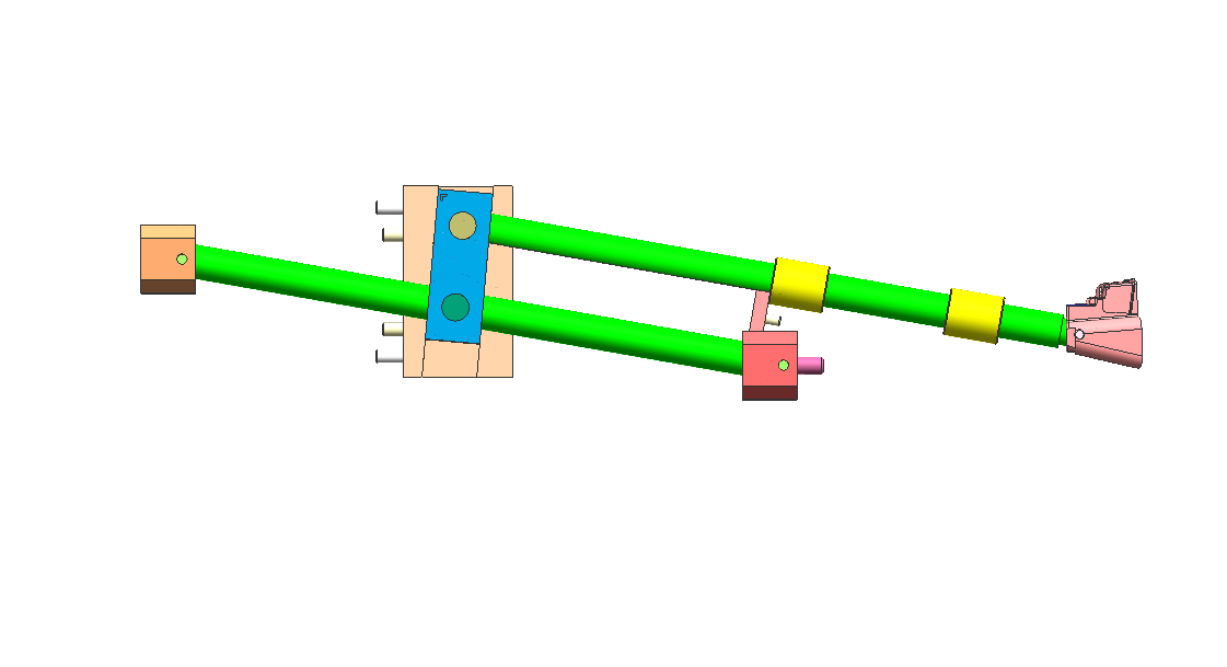
كيف تعمل رافعة القالب: مبدأ "الخطوة الجانبية"
لا تتحرك رافعة القالب مثل المنزلق التقليدي، بل تُحرّك بواسطة نظام الطرد.
أثناء دورة الطرد:
تتحرك الرافعة لأعلى مع لوحة الطرد
في الوقت نفسه، تتبع مسارًا مائلًا
ينتج عن ذلك حركة رأسية وجانبية مُركّبة
هذه الحركة الجانبية - التي تُسمى غالبًا "الخطوة الجانبية" - هي ما يُحرر التجويف.
قاعدة تصميم أساسية
احرص دائمًا على ترك مسافة حركة إضافية لا تقل عن 2 مم بعد عمق القطع السفلي.
أي مسافة أقل من ذلك تزيد من خطر:
علامات الاحتكاك
خدوش السطح
عدم اكتمال التحرير
الخطأ الأكثر شيوعًا: زاوية الرافعة غير الصحيحة
من أكبر أخطاء التصميم زيادة زاوية الرافعة بشكل مفرط لتوفير المساحة.
زاوية الرافعة الموصى بها
النطاق الأمثل: 5° - 11°
منطقة الخطر
أكثر من 15°: خطر كبير للانحشار والفشل
عند الزوايا الحادة:
تزداد القوة الجانبية بشكل ملحوظ
تصبح الحركة الرأسية محدودة
قد تنحشر الرافعة أو قد ينثني القضيب
عندما تكون الزوايا الحادة حتمية
إذا كان تصميمك يتطلب زاوية أكبر، فضع في اعتبارك ما يلي:
قاعدة رافعة مفصلية
تصميم رافعة بفتحة على شكل حرف T
تساعد هذه الميزات على تقليل الضغط على قضيب الرافعة وتحسين المتانة.
اختيار المواد: منع التآكل والتلف
تعمل أنظمة الرفع في ظل:
ضغط عالٍ
درجة حرارة عالية
تلامس معدني مستمر
قد يؤدي اختيار المادة الخاطئة إلى التآكل، حيث تلتصق الأسطح ببعضها وتتلف.
المواد الموصى بها
فولاذ الأدوات H13
فولاذ 718H مُقسّى مسبقًا
إرشادات الصلابة
الهدف: 50-54 HRC
اجعل الرفع أصلب قليلًا من القلب
خيار عالي الأداء
لتقليل أوقات الدورة:
استخدم حشوات من نحاس البريليوم
المزايا:
تبديد أسرع للحرارة
تقليل وقت التبريد
زيادة كفاءة الإنتاج
3 نصائح من الخبراء لتصميم رفع متين
1. أضف دليلًا خلفيًا
ادعم دائمًا الجزء السفلي من قضيب الرفع بكتلة توجيه.
بدون دعم:
يهتز القضيب
يؤدي الاهتزاز إلى ظهور نتوءات وتآكل
2. استخدم أخاديد الزيت
الاحتكاك عدو أي جزء متحرك. أفضل الممارسات:
إضافة أخاديد تشحيم للأسطح المنزلقة
استثناء:
قوالب طبية ← استخدام طلاء DLC بدلاً من الزيت
3. ضبط خط الفصل (PL)
يجب أن يتطابق سطح إغلاق الرافعة تمامًا مع القلب.
حتى فجوة 0.01 مم قد تتسبب في:
ظهور خطوط فاصلة مرئية
جودة سطح رديئة
الرافعة مقابل المنزلق: أيهما الأنسب؟
يعتمد اختيار الرافعة أو المنزلق كليًا على موقع التجويف السفلي.
استخدم المنزلق عندما:
يكون التجويف السفلي خارجيًا
تتوفر مساحة كافية للحركة الجانبية
استخدم الرافعة عندما:
يكون التجويف السفلي داخليًا
المساحة محدودة
الأنظمة الهيدروليكية غير عملية
خلاصة القول: تُعد رافعة القالب من أكثر الحلول فعالية للتجويفات السفلية الداخلية، ولكن فقط عند تصميمها بشكل صحيح.
الرافعة هي أحد أكثر الحلول كفاءة للتجويفات السفلية الداخلية، ولكن فقط عند تصميمها بشكل صحيح. من خلال التحكم في:
الزاوية
فسحة الحركة
اختيار المواد
الدعم الهيكلي
يمكنك تحويل ميزة عالية المخاطر إلى آلية موثوقة وقابلة للتكرار تضمن استمرار خط إنتاجك بسلاسة.
هل تحتاج إلى مساعدة في تحسين تصميم القالب أو حل مشكلات التجاويف المعقدة؟ تفضل بزيارة www.xinkeymould.com للحصول على دعم الخبراء وتحسين أداء أدواتك.
اقرأ المزيد


