

Low-Volume Injection Molding: On-Demand Production & Fast Tooling
23rd October 2026

 author
Protecting a large transparent PC component during a glass-fiber-reinforced PA66 second shot
Project scope. The supplied project brief describes a large transparent PC component that receives a PA66 GF30 structural overmold. This article uses automotive lighting as the application search context because the part combines a transparent cosmetic surface with a reinforced structural section. The final customer application remains subject to project confirmation. The tooling objective was to position the PC insert, control PA66 GF30 flow, and release the finished component with the specified appearance and dimensions.
| Planning a PC and PA66 GF30 overmolding project? Upload 3D CAD files for a DFM review and mold quote |
| Item | Verified project or capability detail |
| Part and materials | Large transparent PC component with a PA66 GF30 structural overmold |
| Application context | Automotive lighting component scenario for SEO targeting; final end use to be confirmed by the customer |
| Primary risks | Insert movement, scratches or whitening, unbalanced filling, flash, cracking, delamination, and dimensional variation |
| Validation route | Insert position, filling stability, interface quality, transparent surface, dimensions, and demolding at T1 |
| XINKEY MOULD resources | 25 years in mold making; 22 in-house designers; 10,000 m² facility; 19+ CNC centers; 90T–750T injection capacity |
| Data fields for quotation | Mold life, target annual volume, lead time, tolerance budget, and defect-rate baseline require customer confirmation |

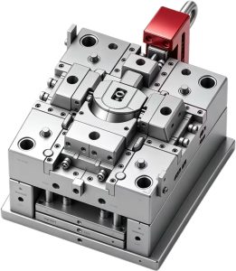
PC and PA66 GF30 overmolding mold with transparent insert
Automotive lighting parts combine a visible transparent surface with mounting, sealing, or reinforcement features. In this project, the PC insert acts as the cosmetic and optical element while PA66 GF30 forms the structural overmold. The mold therefore has to control contact, pressure, flow, and release as one sequence. The supplied brief records successful first-trial samples that met the customer requirements for bonding, dimensional accuracy, and transparent surface appearance.
The engineering review identified functional or low-visibility areas for locating and supporting the PC insert. The visible PC surface was kept outside the primary locating reference. This arrangement defines the insert position during mold closing, PA66 GF30 injection, and mold opening, while keeping clamp and ejection forces away from the cosmetic area.
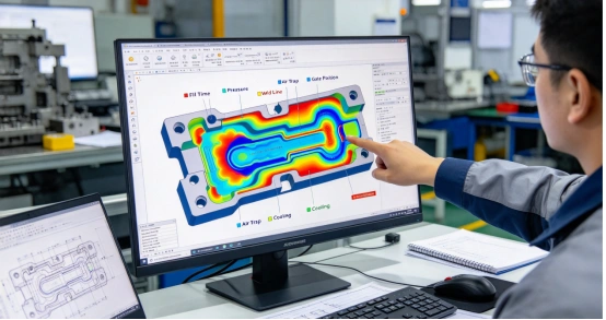
The gate position was arranged around the overmolding zone so PA66 GF30 could fill in a controlled direction. The review considered melt-flow direction, filling balance, pressure distribution, interface geometry, and the risk of insert movement. The first trial validated stable filling and the required PC to PA66 GF30 joint condition.
The PC and PA66 GF30 connection uses a defined mechanical engagement area. PA66 GF30 wraps around the PC geometry to create a controlled joint. The parting line near the joint was placed to manage flash, clamping, and the appearance of the transparent component. The approved samples showed bonding with no delamination or cracking, according to the supplied case brief.
Ejector locations were planned around structural areas of the overmold. The release path was refined to reduce friction and keep ejection marks away from the transparent PC surface. T1 validation included demolding behavior and visual inspection for scratches, whitening, stress marks, and other visible defects.
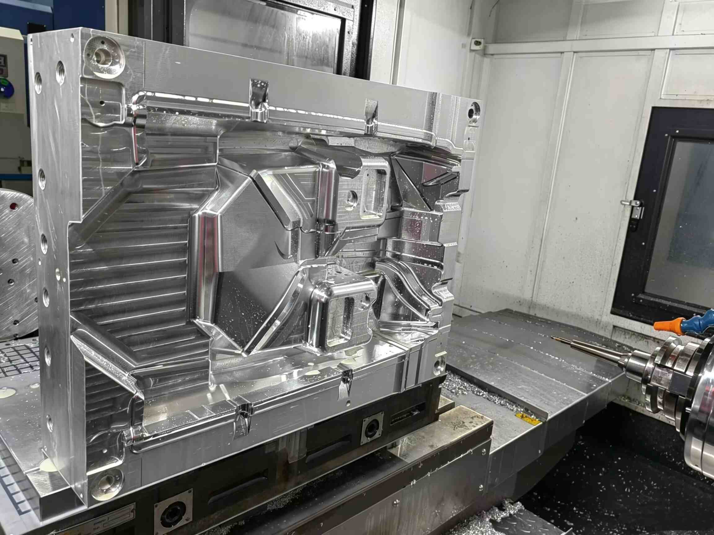
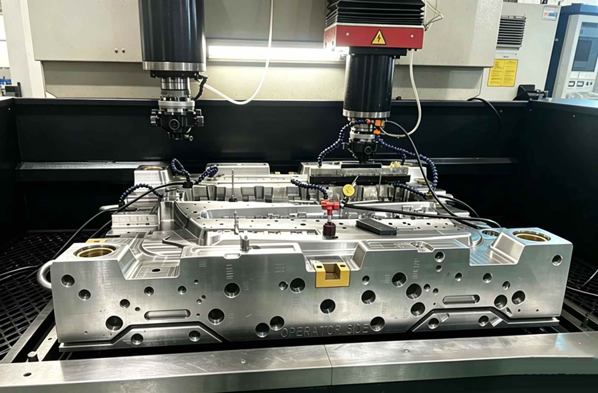
PA66 GF30 overmolding tooling and flow-control features
| Validation area | T1 check | Acceptance evidence |
| Insert control | Measure PC position before and after the second shot | Stable overmolding alignment and no recorded insert movement |
| Interface quality | Inspect the PC and PA66 GF30 joint | Bonding meets the customer requirement with no delamination or cracking |
| Transparent surface | Inspect scratches, whitening, stress marks, and visible defects | Clean transparent PC surface that meets the appearance requirement |
| Dimensions and release | Measure critical dimensions and observe demolding | Dimensions meet validation requirements and the part releases reliably |
The workflow links the case study to XINKEY MOULD service pages: Project Engineering and DFM for insert support, gate direction, interface geometry, and Moldflow review; Precision Mold Machining for CNC, EDM, polishing, and mold assembly; Mold Trial and Production for T1 sampling and production validation; and Automotive solutions for vehicle-component programs.
XINKEY MOULD records ±0.01 mm-level precision control for high-precision CNC machining, more than 7,000 exported mold sets, and mold capacities from 150 kg to 15 tons. These figures describe company capabilities; they are not measured results for this specific PC and PA66 GF30 tool.
What information is needed before the mold is designed?
Provide the 3D model, 2D tolerances, resin grades, cosmetic requirements, expected production volume, machine details, and critical assembly features. The engineering team uses these inputs to plan support, gates, cooling, interface geometry, and ejection.
How is a transparent PC surface protected during PA66 GF30 overmolding?
The mold locates and supports the PC from functional or low-visibility areas, controls the second-shot flow path, and places ejection forces on structural regions. The T1 inspection checks scratches, whitening, stress marks, and visible defects.
Which service covers DFM and Moldflow review?
Use the Project Engineering and DFM service page for a structured review before steel machining. The review can cover wall thickness, draft, gate direction, insert support, parting line, and filling behavior.
Can XINKEY MOULD support the project after mold delivery?
The published workflow covers DFM review, mold design, precision machining, trial molding, dimensional validation, and production support. Scope, timing, and commercial terms are confirmed during quotation.
Have a complex PC and PA66 GF30 overmolding project? Upload your 3D CAD files, material information, annual volume, and target application through the XINKEY MOULD Free Quote page. The service page accepts STEP, STP, IGES, IGS, XT, DWG, PDF, and ZIP files up to 30 MB. For direct contact, use the Contact Us page or email Contact-Xinkey@xinkeymould.com.
Related Posts





Contact Us