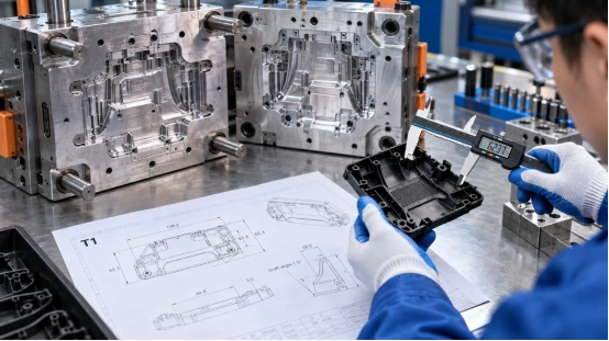
Low-Volume Injection Molding: On-Demand Production & Fast Tooling
23rd October 2026

 author
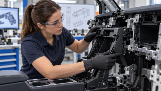
A CAD model can look finished while the moulded part still carries open questions. Will the ribs sink? Will the clips survive assembly? Will the housing warp around a button? Rapid prototype injection moulding answers those questions with real moulded parts made from the planned resin.
The method suits plastic part development that needs functional testing, pilot builds, customer samples, or early sales units. Speed comes from a focused tool scope and engineering work before metal cutting begins.
Rapid injection molding uses a quickly manufactured mould to produce repeatable plastic parts. Many teams also call it prototype injection molding or rapid tooling. The process follows the same basic cycle as production moulding: clamp, inject, pack, cool, open, and eject.
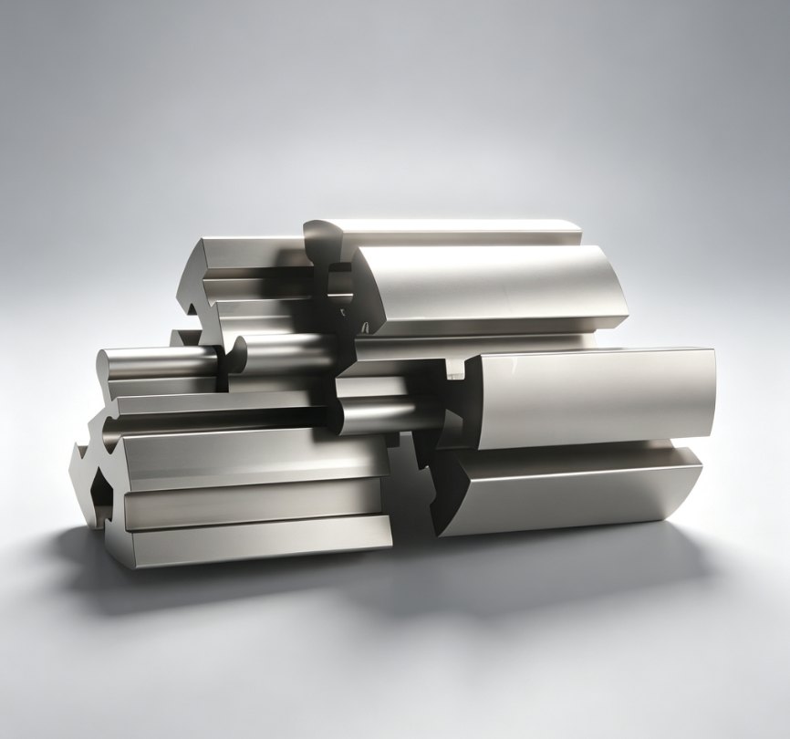
An injection mould prototype commonly uses aluminium, P20, NAK80, or harder inserts in wear areas. Quantity, resin, finish, and tolerance guide the choice. Aluminium may serve a short run. P20 supports welding and design changes, while NAK80 suits polished surfaces.
Production tools may add multiple cavities, hardened steels, hot runners, automated actions, and serviceable wear parts. A rapid tool keeps the build tied to the current test goal.
Use rapid tooling when printed or machined prototypes cannot answer the next engineering question. Moulded resin behaves differently around weld lines, living hinges, snap fits, bosses, and textured walls.
Use production-grade materials to test stiffness, chemical resistance, heat response, or assembly force. ABS suits tough housings, PC supports impact-resistant or clear parts, PP suits living hinges, and PA handles loaded components. Filled PA and high-temperature grades can wear soft tooling quickly.
Low-volume injection molding covers pilot production and limited releases. Bridge tooling can supply saleable units during a long-life mould build and give buyers measured cycle, scrap, and inspection data.
A useful process starts with part requirements. Share the 3D model, 2D drawing, resin grade, colour, finish, quantity, critical dimensions, and assembly context. Mark sealing faces and cosmetic zones. A vague note such as tight tolerance everywhere raises cost and leaves room for argument.
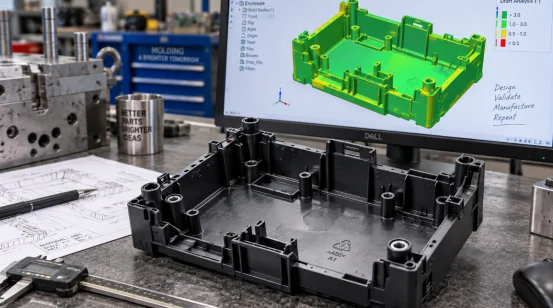
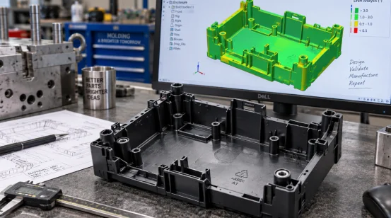
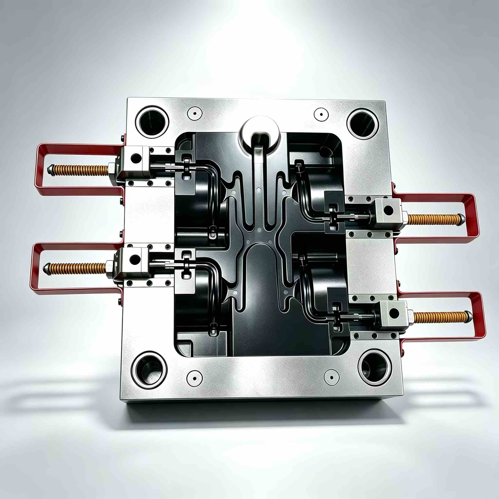
Design for manufacturability checks wall thickness, draft, undercuts, ribs, bosses, parting lines, gates, vents, and ejection. The DFM analysis should also identify dimensions that cross the parting line and features that need sliders, lifters, inserts, sleeves, or unscrewing mechanisms.
Wall sections around 1.5 to 2.5 mm suit many common thermoplastics, though the resin supplier’s range and the part function take priority. Keep adjacent walls close in thickness. Thick boss bases cool slowly and can pull a visible sink into the opposite face. Draft helps the part release; texture usually needs more draft than a polished surface.
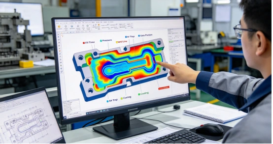
Flow simulation can test gates, runner balance, weld lines, air traps, pressure, and thermal behaviour. It suits thin walls, long flow paths, multi-cavity tools, and appearance parts. Each finding should lead to an action such as moving a gate or revising a cooling channel.
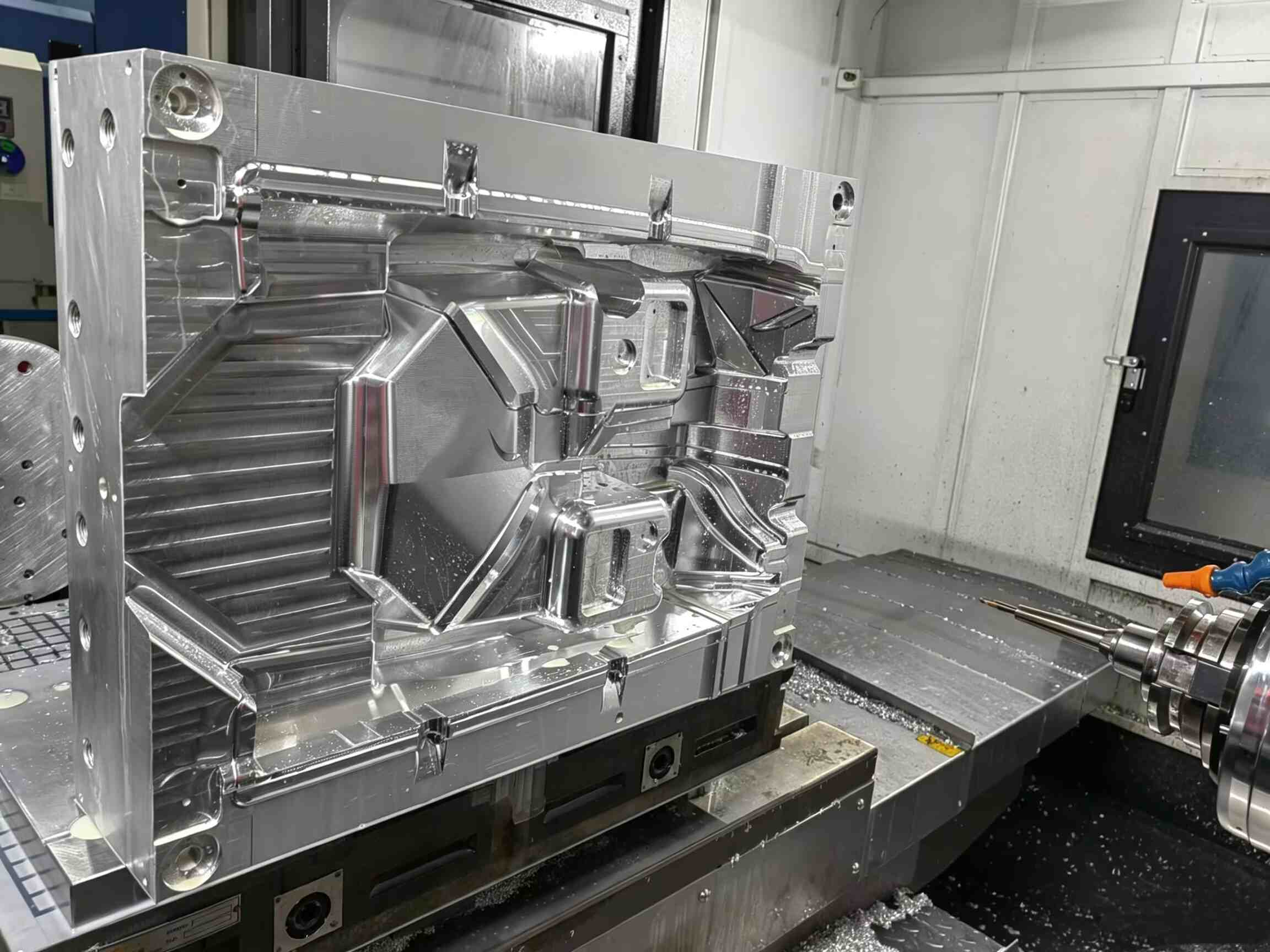
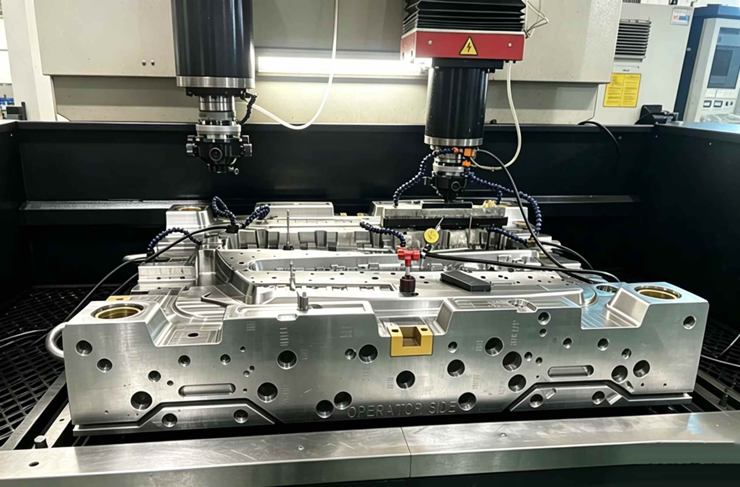
CNC machining forms most cores and cavities. EDM handles deep slots, sharp internal details, and geometry a cutter cannot reach cleanly. Wire cutting, grinding, fitting, and polishing complete the tool.
T0 checks filling, opening, ejection, and safe operation. The team records short shots, flash, burns, sinks, weld lines, warpage, sticking, and dimension drift. T1 samples should include the agreed resin, process record, dimensional report, and remaining actions. A pretty sample from an unstable cycle is still an unfinished result. Shop floors learn this lesson often.
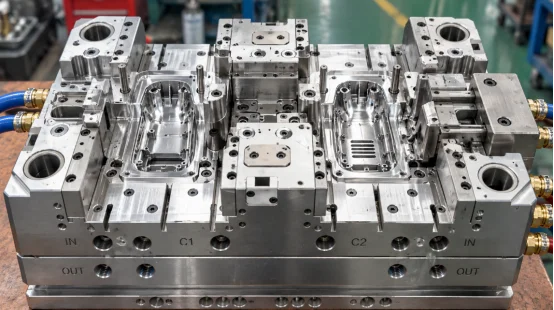
Part quality comes from linked decisions. Gate location affects weld lines and packing. Cooling affects cycle time and warpage. Ejection affects drag marks, whitening, and distortion.
Place the gate where melt can fill the cavity with manageable pressure and pack thick regions. Balanced runners matter in multi-cavity tools because one early-filling cavity can steal pressure from another. Vents at the end of flow paths release trapped air and reduce burns.
Cooling often takes the largest share of the moulding cycle. Channels need even coverage around the core and cavity. Local hot spots keep one area soft while nearby plastic contracts, which can twist a flat housing after ejection. Ejector pins, sleeves, stripper plates, lifters, or air ejection then need enough contact area to move the part without dents.
Compare quotations by scope. The lowest tooling figure says little when the quote omits resin, trials, inspection, changes, or the expected tool life.
Ask each plastic injection mould manufacturer to state the mould material, hardness, cavity count, runner type, tool life, included trials, T1 lead time, dimensional report, maintenance plan, and ownership terms. Confirm press tonnage and shot size. A large projected area needs enough clamp force to control flash.
Review part cost at several quantities. Cold runners suit many short runs, though every shot produces runner material. Hot runners cut waste and may shorten the cycle, while tooling and maintenance cost more. Volume and resin price guide the choice.
Allow time for one correction loop after the first trial. Standard rapid moulds may reach T1 in roughly two to four weeks. Complex unscrewing, insert, or two-material structures can take four to eight weeks. Geometry, steel availability, finish, and inspection scope can move those dates, so a milestone plan is more useful than a single delivery promise.
The trial report should connect each defect with an action and an owner. That record turns a rapid tool into a practical production gate.
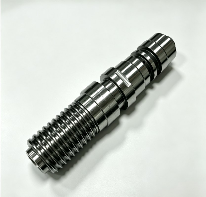
XINKEY MOULD supports this stage through early DFM, mould-flow review, rapid prototype mould development, trial moulding, and bridge production. Its engineering scope covers sliders, lifters, inserts, threaded cores, hot and cold runners, balanced ejection, and cooling layouts for parts that need more than a straight open-and-close tool. Precision machining includes CNC, EDM, and wire cutting, with machining control reaching the +/-0.01 mm level where the feature and inspection method support it.
The team can carry trial findings into mould corrections and low-volume part production, which keeps design feedback, tooling changes, and process records connected. For a buyer, that continuity makes the T1 review easier to audit and gives the production-tool decision a firmer cost and quality basis.
Q1: How Fast Can a Rapid Prototype Mould Produce T1 Samples?
A: A standard tool may reach T1 in about two to four weeks. Slides, unscrewing systems, inserts, two-material structures, special steels, or demanding finishes can extend the schedule to four to eight weeks.
Q2: How Many Parts Can a Rapid Injection Mould Produce?
A: Tool life depends on mould material, resin, pressure, temperature, geometry, and maintenance. Define the required shot count before quoting so the toolmaker can select suitable steel and protect high-wear areas.
Q3: Can You Use the Final Production Resin?
A: Yes, in many projects. Using the intended resin gives better evidence for fit, strength, shrinkage, heat response, and surface quality. Abrasive, corrosive, or high-temperature grades may require steel inserts or a steel tool.
Q4: What Files Should You Send for a Quote?
A: Send a 3D model, a dimensioned 2D drawing, resin grade, colour, finish, quantity, annual forecast, critical tolerances, assembly details, and the required sample date.
Q5: When Should You Move to a Production Mould?
A: Move when the design is stable, trials meet the acceptance criteria, and forecast volume supports a longer-life tool. Use measured cycle time, scrap rate, maintenance needs, and unit cost from the prototype run in that decision.
Related Posts



Contact Us