Mold Cycle Time
Mold Cycle Time: The Hidden Profit Lever in Injection Molding
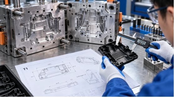
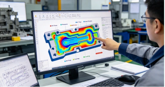
If you’ve spent any time around an injection molding shop floor, you’ll notice one thing pretty quickly: everyone talks about quality, but the real game is time. Cycle time isn’t just a number on the machine screen—it’s directly tied to cost, output, and ultimately, your profit margin. In many projects, cycle time doesn’t get much attention early on. By the time it becomes a concern, the mold design is already fixed and changes are costly. In this article, we’ll walk through what cycle time actually means on the shop floor, what tends to slow it down, and where you can realistically make improvements—without risking part quality. What Is Mold Cycle Time? Mold cycle time refers to the total time required to complete one full injection molding process cycle. That includes: Mold closing Injection (filling) Packing and holding Cooling Mold opening Part ejection In simple terms:Cycle time is basically the time it takes from one mold close to the next shot. At a glance, 25 seconds versus 30 seconds doesn’t raise alarms. But in continuous production, it adds up quickly. Over time, you end up with fewer cycles, which directly means less output from the same resources. That’s where cycle time starts to matter—not on paper, but on your bottom line. Machine cost per part goes up Labor and energy costs increase Delivery timelines stretch That’s why experienced mold designers don’t just design for “good parts”—they design for efficient cycles. Key Factors That Affect Mold Cycle Time Cycle time isn’t controlled by a single parameter. It’s the result of multiple design and process decisions. 1. Cooling Time (The Biggest Factor) Cooling often takes up 60–80% of the total cycle time. What influences it: Part thickness Material type Mold temperature Cooling channel design Thicker parts hold heat longer. Poor cooling layout makes it worse. 👉 If you want faster cycles, start with better cooling—not faster injection. 2. Part Design Design decisions made early on can lock in your cycle time. Key design impacts: Uniform wall thickness → faster cooling Avoiding thick ribs/bosses → less heat concentration Proper draft angles → faster ejection Bad design = longer cooling + ejection problems. 3. Material Selection Different plastics behave differently. For example: PP / PE → faster cooling PC / ABS → slower cooling Glass-filled materials → require more control Choosing material without considering cycle time is a common mistake. 4. Mold Design & Engineering A well-built mold can dramatically reduce cycle time. Critical elements: Optimized cooling channels (conformal cooling if possible) Proper gate location Efficient venting Balanced runner system An average mold “works.”A well-engineered mold prints money faster. 5. Machine Parameters Even with a perfect mold, poor machine settings can slow everything down. Key parameters: Injection speed Holding pressure/time Cooling time setting Clamp open/close speed Fine-tuning matters—but it cannot fix bad design. Practical Ways to Reduce Mold Cycle Time Here’s what actually works in real production environments: Optimize Cooling System First Add cooling channels near hot spots Use baffles or bubblers if needed Consider conformal cooling for complex parts 👉 This gives the biggest ROI. Reduce Wall Thickness (When Possible) Even a small reduction can significantly cut cooling time. Example:3.0 mm → 2.5 mm can reduce cooling time noticeably But always balance strength and function. Improve Mold Venting Better venting allows: Faster filling Reduced burn marks Lower injection pressure Which indirectly shortens cycle time. Use High-Efficiency Mold Materials Beryllium copper inserts (for hot areas) High thermal conductivity steels These help remove heat faster. Automate Where Possible Robotic part removal Faster, consistent ejection Manual handling slows cycles more than people realize. Common Mistakes That Increase Cycle Time Let’s be honest—these happen all the time: Overdesigning wall thickness “just to be safe” Ignoring cooling during mold design Poor gate placement leading to uneven filling Setting excessive cooling time as a safety buffer Trying to fix design problems with machine parameters These decisions quietly eat into your margins. Cycle Time vs. Part Quality: Finding the Balance Reducing cycle time too aggressively can backfire. You may see: Warpage Sink marks Internal stress Dimensional instability The goal is not the shortest cycle—it’s the optimal cycle. Final Thoughts Mold cycle time is one of the most underestimated factors in injection molding profitability. It’s not just a processing parameter—it’s the result of: Smart part design Thoughtful mold engineering Proper material selection Controlled processing If you think about cycle time early—while the part and mold are still being designed—you give yourself much more room to optimize. Once the tooling is finished, improving it becomes a lot harder and more expensive. FAQ Q: What is a “good” cycle time in injection molding?A: There isn’t a single benchmark. It depends on the part—its size, geometry, and material. Simple, thin-wall parts can run quite fast, often under 20 seconds. Larger or thicker parts usually need more time, sometimes 40 seconds or more. Q: What affects cooling time the most?A: Most of the time, it’s the wall thickness and the cooling layout inside the mold. Thicker areas take longer to release heat, and if the cooling channels aren’t placed well, the delay becomes even more obvious. Q: Why is my cycle time too long?A: Common causes include thick parts, poor cooling design, conservative machine settings, or inefficient mold layout.
READ MORE
Mold lifter
Why Internal Undercuts Are a Serious Problem in Injection Molding
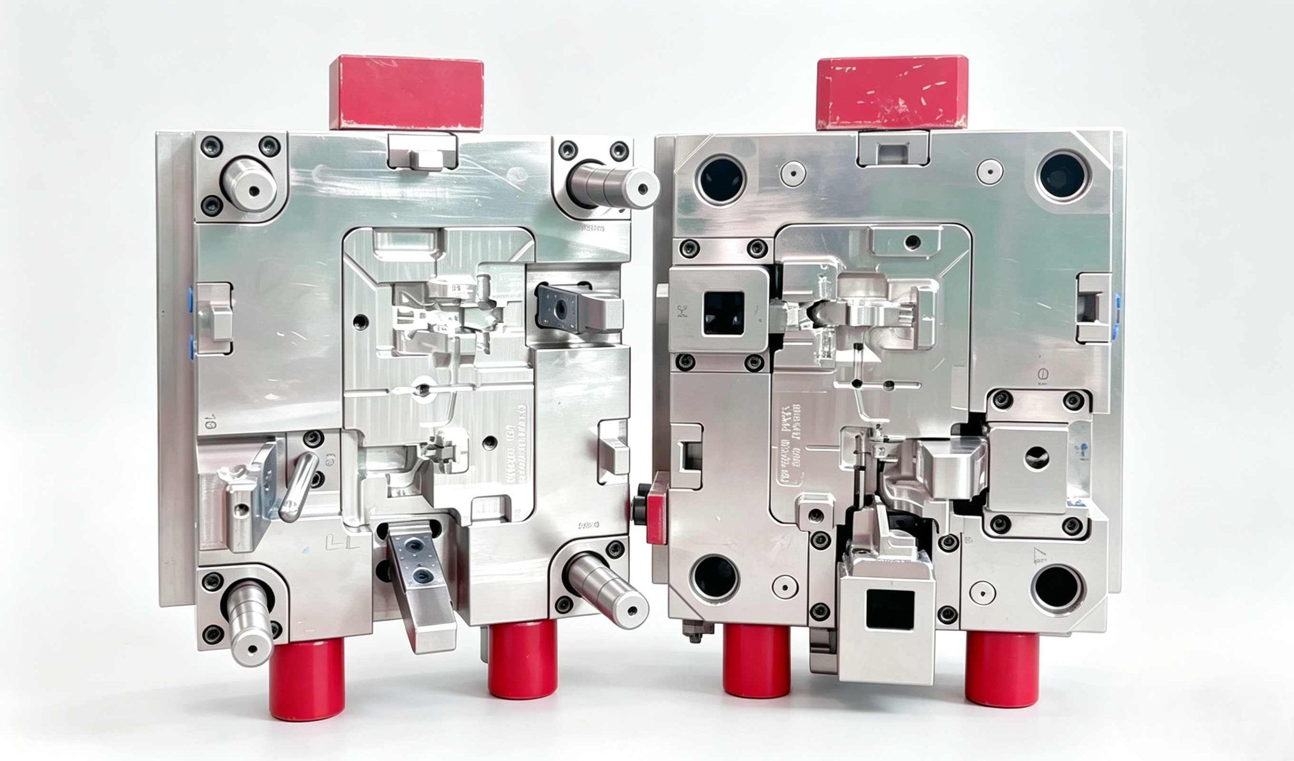
Let’s be honest: internal undercuts are a nightmare for mold designers. Unlike external features, they can’t be handled with standard sliders. If the geometry isn’t designed correctly, the consequences are serious: Parts stuck permanently on the core Surface damage or scuffing Lifter rod breakage Costly production downtime When dealing with internal clips or bosses, the mold lifter becomes the most reliable mechanical solution. How a Mold Lifter Works: The “Side-Step” Principle A mold lifter doesn’t move like a traditional slider. Instead, it is driven by the ejector system. During the ejection cycle: The lifter moves upward with the ejector plate At the same time, it follows an angled path This creates a combined vertical + lateral motion This lateral movement—often called the “side-step”—is what releases the undercut. Key Design Rule Always allow at least 2 mm of extra travel beyond the undercut depth. Anything less increases the risk of: Drag marks Surface scratches Incomplete release The Most Common Mistake: Incorrect Lifter Angle One of the biggest design errors is pushing the lifter angle too steep to save space. Recommended Lifter Angle Optimal range: 5° – 11° Risk Zone Above 15°: High risk of binding and failure At steeper angles: Lateral force increases significantly Vertical motion becomes restricted The lifter may jam or the rod may buckle When Steep Angles Are Unavoidable If your design forces a larger angle, consider: Hinged lifter base T-slot lifter design These help reduce stress on the lifter rod and improve durability. Material Selection: Prevent Galling and Wear Lifter systems operate under: High pressure High temperature Continuous metal-to-metal contact Choosing the wrong material can lead to galling, where surfaces weld together and fail. Recommended Materials H13 tool steel 718H pre-hardened steel Hardness Guideline Target: 50–54 HRC Keep the lifter slightly harder than the core High-Performance Option For faster cycle times: Use Beryllium Copper inserts Benefits: Faster heat dissipation Reduced cooling time Increased production efficiency 3 Expert Tips for a Bulletproof Lifter Design 1. Add a “Tail” Guide Always support the bottom of the lifter rod with a guide block. Without support: The rod vibrates Vibration leads to flash and wear 2. Use Oil Grooves Friction is the enemy of any moving component. Best practice: Add lubrication grooves to sliding surfaces Exception: Medical molds → use DLC coating instead of oil 3. Control the Parting Line (PL) Fit The lifter shut-off surface must match the core perfectly. Even a 0.01 mm gap can cause: Visible witness lines Poor surface quality Lifter vs Slider: Which One Should You Use? Choosing between a lifter and a slider depends entirely on undercut location. Use a Slider When: The undercut is external There is enough space for side action Use a Lifter When: The undercut is internal Space is limited Hydraulic systems are not practical Final Thoughts A mold lifter is one of the most efficient solutions for internal undercuts—but only when designed correctly. By controlling: Angle Travel clearance Material selection Structural support You can turn a high-risk feature into a reliable, repeatable mechanism that keeps your production line running smoothly. Need help optimizing your mold design or solving complex undercuts?Visit www.xinkeymould.com to get expert support and improve your tooling performance.
READ MORE
PARTING LINE
The Parting Line: Where Your Mold Design Meets Reality
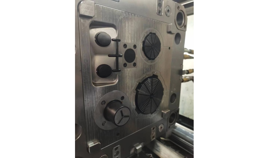
Ever run your thumb along a new plastic part and felt that sharp, ugly ridge digging into your skin? That’s the parting line. It’s supposed to be a seamless transition—but more often than not, it becomes the scar of a rushed design. On a 2D CAD screen, the parting line looks like a simple intersection. But on the shop floor, it’s a high-stakes battlefield—where the core and cavity meet. If these two halves don’t “kiss” perfectly, your part is compromised before it even leaves the press. Why the Parting Line Matters A poorly designed parting line isn’t just an eyesore—it’s a profit killer: ❌ Manual de-flashing costs ❌ Higher scrap rates ❌ Repeated DFM revisions ❌ Tool wear and maintenance 1. Stop Calling It a “Line” — It’s a Strategic Split Think of the parting line as the mechanical equator of your part. It determines whether your part can be released from the mold—or gets trapped inside it. Common Pitfalls 🔴 The “Trapped” Nightmare (Undercuts)Misplace the parting line by even 1 mm, and you create an undercut.Now your simple mold suddenly requires: Slides Lifters Complex mechanisms ➡️ Result: Tooling cost can double instantly 🔴 The “Kiss-Off” Surface ProblemThe parting line isn’t just a boundary—it’s a high-pressure seal. Complex geometries like: Zig-zags Sharp transitions Steep curves …lead to faster wear and sealing failure. ✅ Golden Rule Keep it flat. Keep it simple. Flat parting lines = easier machining Better sealing performance Longer tool life 2. The Messy Reality of Flash (And Why It’s Bleeding Your Profits) If your parts have a thin, unwanted fringe around the edges—you’re dealing with flash. In the shop, we call it “bleeding.” Why Flash Happens During injection, molten plastic is under extreme pressure and will escape through any gap. 🔧 Root Causes: • Steel Fatigue Shut-off surfaces wear down over time Edges round off after high cycle counts • Poor Alignment Core and cavity not perfectly matched Even microscopic gaps cause flash • The “Tonnage Trap”Increasing clamp force won’t fix bad design. More tonnage = more damage (vent crushing, plate deformation) ⚠️ Reality Check (New Molds) If you see flash during the first T1 trial: 👉 It’s NOT a machine issue👉 It’s a tooling problem Fix the shut-off alignment, not the press settings. 3. How to Hide the Parting Line (Designer’s Secret) The best parting line is the one no one notices. High-end brands like Apple or Dyson obsess over this detail—and you should too. Pro Techniques ✔ Follow the EdgePlace the parting line along sharp edges or corners. ✔ Use the “Step” MethodHide it inside: Grooves Decorative lines Design breaks ✔ Texture Contrast One side matte One side glossy ➡️ Turns a flaw into a design feature 4. Why Draft Angle Is Your Best Friend You can’t design a proper parting line without draft angle. Every wall must taper away from the mold. Without Draft Parts scrape during ejection Surface damage (drag marks) Galling (white scratches) ✅ Recommended Draft Angles Smooth surfaces: ≥ 0.5° Textured surfaces: ≥ 3° More draft = easier ejection + better surface finish 5. The Bottom Line: Consult Early One of the biggest mistakes designers make: Finishing the design… then “throwing it over the wall” to the mold maker. ✅ Best Practice Engage your mold maker early and ask: Where will the parting line be? Will the shut-off surfaces wear quickly? Can we move the line to a hidden area? Final Takeaway A few hours of DFM discussion today can save: Weeks of rework Thousands in scrap Endless frustration on the shop floor In Short The parting line isn’t just a line—it’s where design meets manufacturing reality.
READ MORE
Mold Ejection
The Art of the Exit: Why Mold Ejection is More Than Just a Push
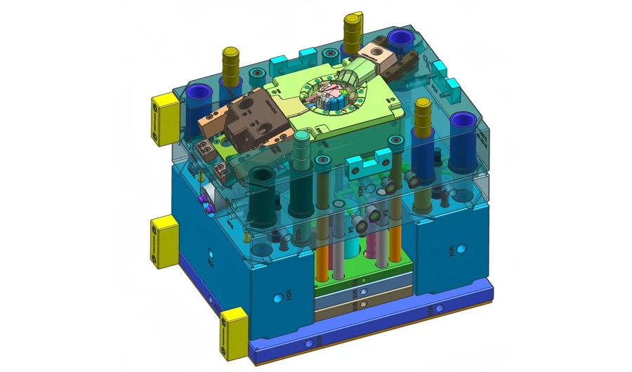
It’s funny how we obsess over every millisecond of the injection phase, yet the exit—the most stressful part of the entire cycle—is often an afterthought. Getting plastic in is one thing; getting it out in one piece is where the real engineering happens. Mold ejection is the final hurdle.You’ve spent the cycle filling, packing, and cooling a perfect part, but if your exit strategy is flawed, you’ll end up with stress marks, distortion, or parts stuck to the core. Here’s why a smooth ejection is the hallmark of a well-engineered tool: 1. The Battle Against Friction and Vacuum The moment the mold opens, the plastic part is gripping the core like a vice. As the material cools, it shrinks onto the steel—creating significant friction. But there’s a second, invisible enemy: vacuum. In deep-draw parts or bucket-style geometries, the part forms a seal against the core. If you rely on ejector pins alone, the vacuum will pull back against the force, causing the part to buckle or collapse. That’s why smart tooling doesn’t rely on brute force. Instead, solutions like: Air poppets Timed air blasts are used to break the vacuum seal before the ejector pins even engage. 2. Balance is Everything: Avoiding the “Punch-Through” One of the most common defects in poor ejection design is stress whitening—those visible white marks where ejector pins push too hard. Ejection must be balanced. If pins aren’t strategically placed around high-friction areas (like ribs or bosses), the part can: Tilt Bind Fail unevenly When that happens, pins don’t eject the part—they punch through it. A well-designed system: Maximizes contact area Distributes force evenly Uses solutions like stripper plates for thin-wall parts This ensures controlled, uniform release. 3. The Silent Hero: Draft Angles You can invest in the most advanced ejection system in the world—but without proper draft angles, you’re fighting a losing battle. Draft is the slight taper on vertical walls. Even 0.5° can make the difference between: A clean release A stuck part requiring manual removal And on textured surfaces? Draft becomes even more critical. The plastic effectively “locks” into the mold texture. Rule of thumb: the more draft, the better. 4. Timing and Thermal Balance Ejection is not just about how you push—but when. Too early:The part is still soft → pins leave indentations or cause deformation Too late:The part grips the core too tightly → excessive force leads to damage Miss that window, and you’re no longer ejecting—you’re forcing failure. Modern tooling has evolved beyond traditional mold release sprays. Instead, many high-performance molds now use: DLC (Diamond-Like Carbon) coated pins These coatings: Reduce friction Improve heat control Extend tool life Enable faster cycle times Most importantly, they allow parts to release cleanly—without contamination or residue. The Bottom Line A great mold doesn’t just produce a perfect part—it produces that part consistently, automatically, and reliably. If an operator has to stand by the machine to help parts fall out, the ejection system has already failed. Design for the Exit At [Your Company Name], we don’t treat ejection as an afterthought. From: Stripper plate systems Multi-stage ejection Advanced coatings We engineer every detail to ensure that each part exits the mold as perfectly as it was formed. Because in injection molding, the final step is just as critical as the first. 如果你要,我可以帮你再优化一版更偏营销型(更适合获客)或者SEO关键词版本(适合Google排名) 👍 SEO关键词版本 好,这一版我帮你做成更偏SEO优化 + 仍然专业好读的博客版本(适合官网 + Google收录 + LinkedIn引流)👇 Mold Ejection in Injection Molding: Design Principles for Smooth Part Release In injection molding, most engineers focus heavily on filling, packing, and cooling. However, one of the most critical stages is often overlooked: mold ejection. A well-designed mold doesn’t just create a perfect part—it ensures that the part is released smoothly, consistently, and automatically. Poor ejection design leads to: Stress whitening Part deformation Sticking on the core Increased cycle time Manual intervention In this article, we break down the key mold ejection design principles that ensure high-quality, repeatable production. What is Mold Ejection in Injection Molding? Mold ejection is the final stage of the injection molding cycle, where the cooled plastic part is removed from the mold using mechanical systems such as: Ejector pins Stripper plates Air ejection systems This step directly affects: Part quality Cycle efficiency Tool longevity 1. Friction and Vacuum in Mold Ejection During cooling, plastic shrinks and tightly grips the mold core, creating high friction forces. In deep or closed geometries, an additional issue occurs: vacuum formation. This vacuum can: Prevent proper release Cause part collapse Increase ejector force requirements Best Practice: Break the Vacuum To improve mold release: Use air poppets Apply timed air blasts Design venting paths These methods reduce resistance before mechanical ejection begins. 2. Ejector Pin Design and Placement Improper ejector pin layout is one of the leading causes of defects in injection molded parts. Common Issues: Stress whitening Pin marks Punch-through defects Design Guidelines: Place pins near high-resistance areas (ribs, bosses) Ensure balanced force distribution Increase contact surface area For thin-wall parts, consider: Stripper plates instead of pins Full-perimeter ejection for uniform force 3. Importance of Draft Angles in Mold Design Draft angle is essential for reducing friction during part ejection. Without proper draft: Parts stick to the core Ejection force increases Surface defects become more likely Recommended Draft Angles: Smooth surfaces: ≥ 0.5° Textured surfaces: ≥ 1.5°–3° Key Insight:More draft equals easier release and longer mold life. 4. Ejection Timing and Cooling Balance Correct ejection timing is critical in injection molding. Ejecting Too Early: Part is still soft Leads to deformation and pin marks Ejecting Too Late: Part shrinks tightly onto core Requires excessive force Increases risk of damage Optimization Strategy: Maintain proper cooling system design Control mold temperature Synchronize ejection with material properties 5. Advanced Solutions: Low-Friction Coatings Modern molds increasingly use DLC (Diamond-Like Carbon) coatings on ejector pins. Benefits: Reduced friction Improved wear resistance Better thermal stability Cleaner part release (no mold release spray needed) This helps: Shorten cycle time Improve consistency Reduce maintenance Why Mold Ejection Matters for Production Efficiency A poorly designed ejection system can: Increase scrap rate Require manual part removal Slow down production Damage tooling A well-optimized system ensures: Fully automatic production Consistent part quality Reduced downtime Lower long-term cost Conclusion: Design for Ejection First In high-quality plastic injection mold design, ejection should never be an afterthought. From ejector pin layout to draft angle optimization and air-assisted release, every detail plays a role in achieving: Smooth part release High production efficiency Reliable mold performance Looking for Reliable Injection Mold Design? At Xinkey Mould, we specialize in: High-performance injection molds Optimized ejection systems Cost-effective tooling solutions We design every mold with efficient part release in mind, ensuring your production runs smoothly from first shot to full-scale manufacturing.
READ MORE
Inside the Press: A Real-World Look at the Injection Molding Cycle
Introduction In modern manufacturing, injection molding is the heavy hitter for high-volume, precision plastic parts. But for most designers, the magic happens behind closed steel doors. Understanding the mechanical “heartbeat” of the press is the first step toward a design that actually works on the shop floor, not just in a CAD simulation. Here is how the cycle actually breaks down: Step 1: The Lockdown (Clamping) Before a single pellet of resin moves, the press has to secure the tool. We’re talking about massive force here—often hundreds of tons—to keep the A-side and B-side from blowing apart during the shot. The Pro View: Don’t underestimate surface area. If you’re molding a part the size of a dinner plate, that internal pressure is fighting to force the mold open. Without enough “tonnage” (clamping force), you get flash—that messy plastic bleed that ruins your part’s edges. Step 2: The Shot (Injection) Once the tool is clamped tight, the screw drives forward. This isn’t just a simple fill; it’s a high-velocity ramming of molten resin through the nozzle and into the tool’s geometry. The Hidden Challenge: Every mold cavity is already full of air. As the plastic slams in, that air needs an immediate exit strategy. This is why we obsess over venting. If that air gets trapped and compressed, it heats up instantly—causing “dieseling” or those ugly black burn marks on your finished part. Step 3: The Wait (Cooling) Fill is done. Now, the clock starts. Cooling is usually the “dead time” in the cycle, yet it accounts for roughly 70% of the total process time. Physics at Work: We aren’t just letting it sit. We are aggressively pulling heat out via internal water lines. The Design Reality: This is where uniform wall thickness becomes your best friend. If one section of your part stays hot while another freezes, the part will literally fight itself as it shrinks. The result? Sink marks or that dreaded warpage that sends parts to the scrap bin. Step 4: Plasticizing – Prepping the Next Shot The machine is a master multitasker. Even while the current part is still solidifying in the mold, the screw is already backing up to prepare for what’s next. What’s actually happening: It’s chewing through raw pellets from the hopper, using a brutal combination of heater bands and pure mechanical shear friction to prep the next “shot.” We call this screw recovery, and getting the speed and back pressure right is the secret sauce for a consistent melt density. Step 5: Ejection – The Moment of Truth Once the part hits its target temperature and gains enough structural “backbone,” the mold cracks open. The Release: This is where the ejector pins—those tiny mechanical fingers—shove the part off the core. If your draft angles aren’t spot on, you’ll hear a “crunch” or see drag marks that ruin a perfectly good finish. It’s the ultimate test of your tool’s design. Injection molding isn’t just about pushing a button and watching parts fall into a bin. It’s a delicate balance of temperature, pressure, and timing. If you skip the DFM (Design for Manufacturability) stage, you aren’t just risking a bad part—you’re risking your entire production timeline. Step 6: Post-Process – Part Recovery & The Runner Strategy The machine’s internal cycle is over, but the work isn’t done until the part is shelf-ready. Whether it’s dropped into a collection bin or snatched by a robotic arm, the final stage is about separation and logistics. The Pro View: In a standard “cold runner” setup, your part comes out attached to a plastic “scaffolding” (the runner). We clip these off, and in a sustainable shop, those runners are immediately tossed into a granulator to be turned into regrind. This minimizes material waste and keeps your part cost down. The High-Volume Hack: If you’re running millions of units, we’d likely steer you toward a Hot Runner system. While hot runners demand more upfront capital, they streamline the process by bypassing the runner system entirely. You get zero scrap and a much leaner cycle time. After a quick weigh-and-count for accuracy, we box them up and get them moving—on their way to your facility without any unnecessary secondary Ops. Got a complex design that’s giving you headaches? Don’t wait until you’re on the shop floor to find the flaws. Reach out to our team for a deep-dive DFM analysis, and let’s get your project running as smooth as a hot runner system.
READ MORE
The Engineering Secrets of High-Speed Automatic Unscrewing Molds
If you are manufacturing parts with internal or external threads—like pipe fittings, cosmetic caps, or industrial valves—you know that the “unthreading” phase is the biggest bottleneck in the injection cycle. In many standard shops, this is still done via manual unscrewing or slow, secondary operations. At Xinkey Mould, we see threading not just as a feature, but as a mechanical puzzle to be automated. Here is why engineering an Automatic Unscrewing System is the best investment for high-volume threaded parts. The Gear-Driven Heart: Rack and Pinion vs. Hydraulic Motors The core of an unscrewing mold is its drive mechanism. There is no “one-size-fits-all” solution here. Rack and Pinion: For high-speed, synchronized movements, we often design a rack-and-pinion system driven by the mold’s opening stroke. It’s purely mechanical and incredibly fast. Hydraulic or Electric Motors: When the thread is too long or requires multiple rotations, we integrate precision motors. The secret Xinkey has learned over 25 years? It’s the synchronization. If the core doesn’t retreat at the exact same rate as the thread pitch, you’ll strip the plastic threads before the part even leaves the mold. Our designers use 3D simulation to map this “travel-to-rotation” ratio to the micron. Solving the “Friction” Nightmare Threaded cores are constantly rotating against the mold cavity. This creates massive friction and heat. Standard mold shops often face “galling” (metal-on-metal seizing) after only a few thousand shots. We solve this by choosing the right “muscle” for the mold. We use hardened H13 or S136 steel for the rotating cores, often treated with specialized low-friction coatings (like DLC). Furthermore, we design internal cooling channels inside the rotating core—a high-level engineering feat that ensures the plastic sets quickly and the threads stay crisp, shot after shot. The ROI: Why “Cheap” Molds Cost You More We often see clients come to us after buying a cheaper, manual unscrewing mold elsewhere. They saved $5,000 on the tool but are spending $2,000 every month on labor and scrap parts. An automatic unscrewing mold from Xinkey might have a higher upfront cost, but it eliminates manual intervention. By shaving 5 seconds off a cycle and removing the need for a human operator, the mold usually pays for itself within the first few months of production. The Xinkey Advantage When you send us a 3D file for a threaded part, our 22 designers don’t just look at the shape. We look at the Pitch, the Material Shrinkage, and the Cycle Time. We build tooling that allows you to hit the “Start” button and let the machine do the work 24/7.
READ MORE
Products
Contacts
WhatsApp
Email