Mold lifter

Why Internal Undercuts Are a Serious Problem in Injection Molding

  • Why Internal Undercuts Are a Serious Problem in Injection Molding Aronna Zheng
  • 15th April 2026

Let’s be honest: internal undercuts are a nightmare for mold designers. Unlike external features, they can’t be handled with standard sliders.

If the geometry isn’t designed correctly, the consequences are serious:

  • Parts stuck permanently on the core
  • Surface damage or scuffing
  • Lifter rod breakage
  • Costly production downtime

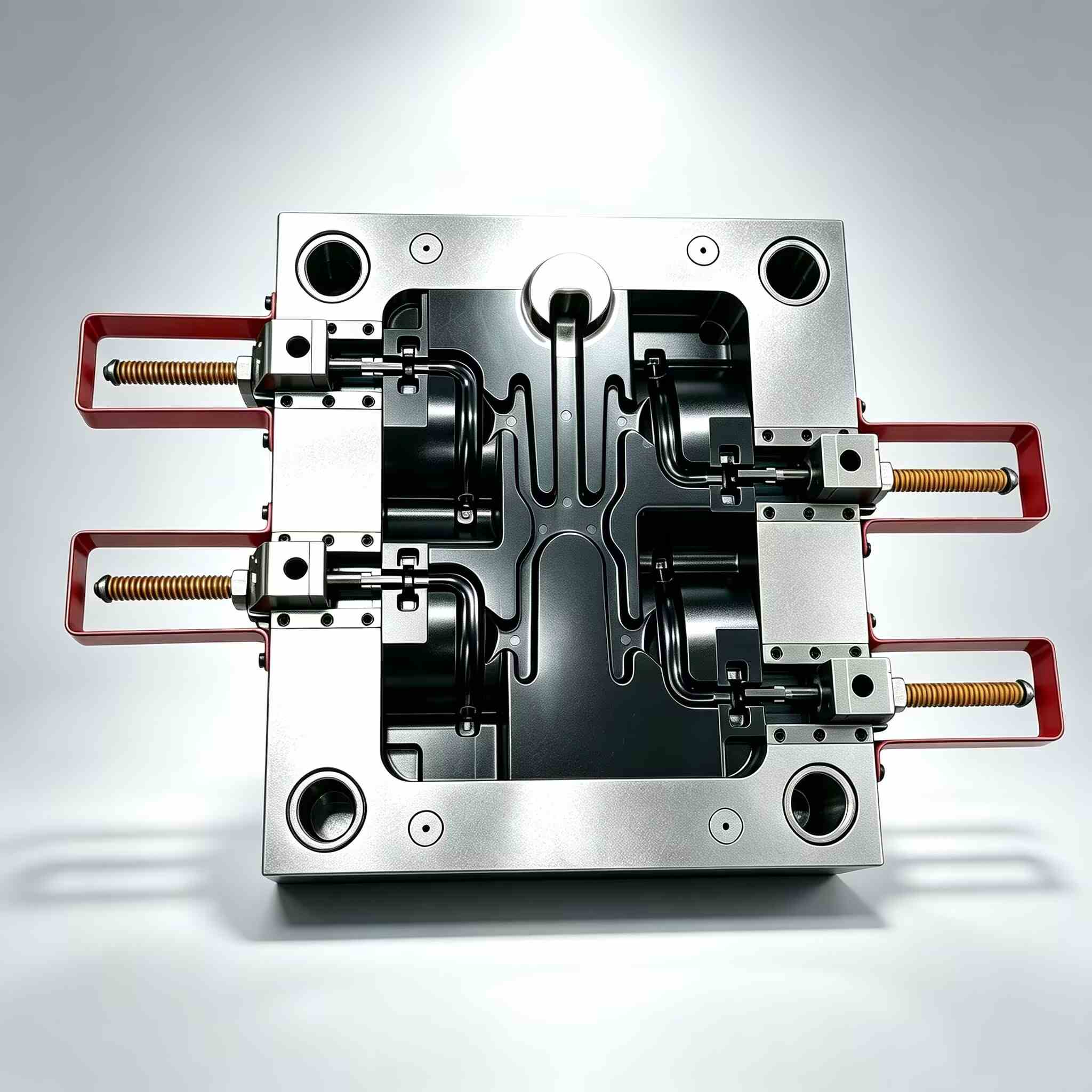
When dealing with internal clips or bosses, the mold lifter becomes the most reliable mechanical solution.


How a Mold Lifter Works: The “Side-Step” Principle

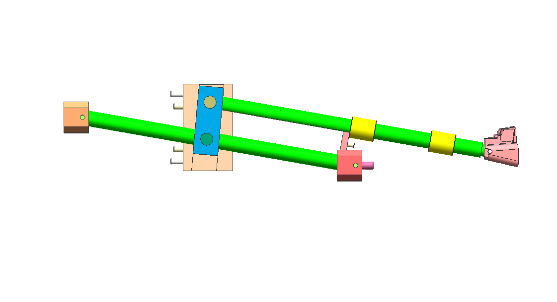
A mold lifter doesn’t move like a traditional slider. Instead, it is driven by the ejector system.

During the ejection cycle:

  • The lifter moves upward with the ejector plate
  • At the same time, it follows an angled path
  • This creates a combined vertical + lateral motion

This lateral movement—often called the “side-step”—is what releases the undercut.

Key Design Rule

Always allow at least 2 mm of extra travel beyond the undercut depth.

Anything less increases the risk of:

  • Drag marks
  • Surface scratches
  • Incomplete release

The Most Common Mistake: Incorrect Lifter Angle

One of the biggest design errors is pushing the lifter angle too steep to save space.

Recommended Lifter Angle

  • Optimal range: 5° – 11°

Risk Zone

  • Above 15°: High risk of binding and failure

At steeper angles:

  • Lateral force increases significantly
  • Vertical motion becomes restricted
  • The lifter may jam or the rod may buckle

When Steep Angles Are Unavoidable

If your design forces a larger angle, consider:

  • Hinged lifter base
  • T-slot lifter design

These help reduce stress on the lifter rod and improve durability.


Material Selection: Prevent Galling and Wear

Lifter systems operate under:

  • High pressure
  • High temperature
  • Continuous metal-to-metal contact

Choosing the wrong material can lead to galling, where surfaces weld together and fail.

Recommended Materials

  • H13 tool steel
  • 718H pre-hardened steel

Hardness Guideline

  • Target: 50–54 HRC
  • Keep the lifter slightly harder than the core

High-Performance Option

For faster cycle times:

  • Use Beryllium Copper inserts

Benefits:

  • Faster heat dissipation
  • Reduced cooling time
  • Increased production efficiency

3 Expert Tips for a Bulletproof Lifter Design

1. Add a “Tail” Guide

Always support the bottom of the lifter rod with a guide block.

Without support:

  • The rod vibrates
  • Vibration leads to flash and wear

2. Use Oil Grooves

Friction is the enemy of any moving component.

Best practice:

  • Add lubrication grooves to sliding surfaces

Exception:

  • Medical molds → use DLC coating instead of oil

3. Control the Parting Line (PL) Fit

The lifter shut-off surface must match the core perfectly.

Even a 0.01 mm gap can cause:

  • Visible witness lines
  • Poor surface quality

Lifter vs Slider: Which One Should You Use?

Choosing between a lifter and a slider depends entirely on undercut location.

Use a Slider When:

  • The undercut is external
  • There is enough space for side action

Use a Lifter When:

  • The undercut is internal
  • Space is limited
  • Hydraulic systems are not practical

Final Thoughts

A mold lifter is one of the most efficient solutions for internal undercuts—but only when designed correctly.

By controlling:

  • Angle
  • Travel clearance
  • Material selection
  • Structural support

You can turn a high-risk feature into a reliable, repeatable mechanism that keeps your production line running smoothly.

Need help optimizing your mold design or solving complex undercuts?
Visit www.xinkeymould.com to get expert support and improve your tooling performance.

Table of Contents

Blog

Related Posts

Frequently Asked Question

A: For standard molds, it’s 2-4 weeks. Complex projects like unscrewing or 2K molds may take 4-8 weeks, depending on engineering depth.
We typically deliver a complete quotation within 3-4 working days after receiving your 3D CAD file and design requirements. For simple parts with clear specifications, we can often turn around a quote in 48 hours. For complex assemblies or family molds requiring detailed engineering review, it may take up to 4 working days to ensure we evaluate all aspects thoroughly. Along with the quotation, you receive a free preliminary DFM (Design for Manufacturing) report. This includes: identified design risks (thin walls, undercuts, weld lines, sink marks), recommended gate locations, suggested draft angles, and potential cost-saving modifications. This DFM report has saved many customers thousands of dollars by catching issues before steel is cut. If you have an urgent deadline, let us know. We can prioritize your quote and often deliver within 24-48 hours. We understand that in product development, timing is everything.
A: We strictly follow DME, HASCO, and LKM standards based on your specific regional or project requirements.
Our mature 8-step mold making process (25 years optimized): 1. DFM evaluation: Mold flow analysis, annotated report in 2-3 days 2. 3D mold design sent for confirmation 3. Certified mold steel purchased with certificates 4. 3/5-axis CNC rough & semi-finish machining 5. EDM, wire EDM & jig grinding for precision work 6. Mold assembly + cooling pressure test 7. T1 trial: 10–30 inspected molded samples 8. Fine-tuning, polishing, CMM report & shipment Photos & progress reports provided at all stages.
plastic injection mold

Contact Us


    Products
    Contacts
    WhatsApp
    Email