
Pourquoi les contre-dépouilles internes constituent un problème sérieux en moulage par injection
-
 Aronna Zheng
- 15 avril 2026
Soyons honnêtes : les contre-dépouilles internes sont un véritable cauchemar pour les concepteurs de moules. Contrairement aux éléments externes, elles ne peuvent pas être traitées avec des curseurs standard.
Si la géométrie n'est pas correctement conçue, les conséquences sont graves :
- Pièces collées de façon permanente au noyau
- Dommages ou éraflures de surface
- Rupture de la tige de poussoir
- Arrêts de production coûteux
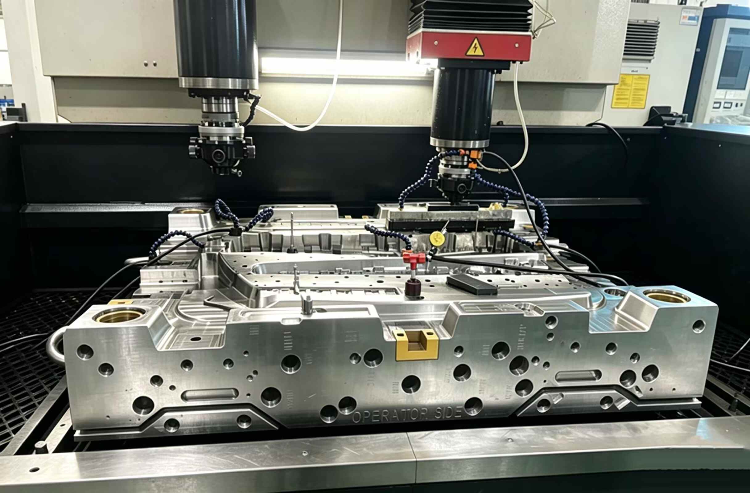
Lorsqu'il s'agit de clips ou de bossages internes, lève-moule devient la solution mécanique la plus fiable.
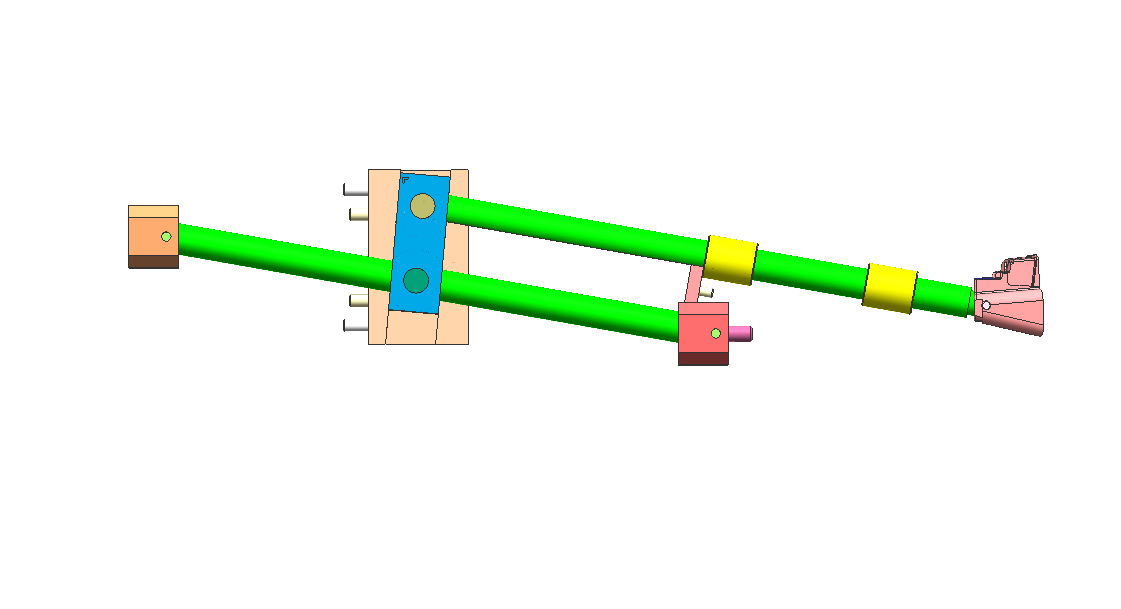
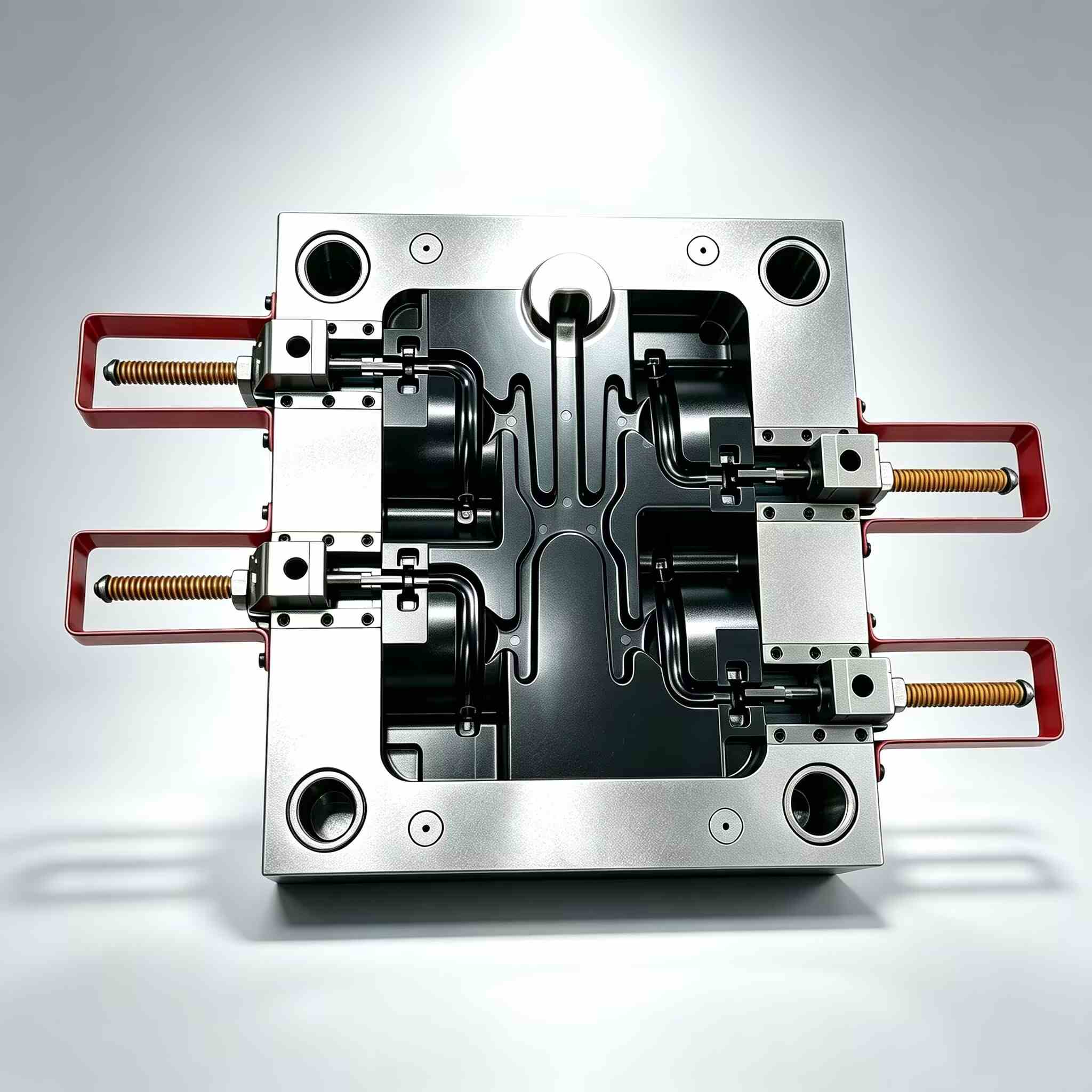
Fonctionnement d'un lève-moule : le principe du « pas latéral »
Un lève-moule ne fonctionne pas comme un coulisseau traditionnel. Il est actionné par le système d'éjection.
Durant le cycle d'éjection :
- Le lève-personne se déplace vers le haut avec la plaque d'éjection
- En même temps, il suit un chemin en angle
- Cela crée une combinaison mouvement vertical + latéral
Ce mouvement latéral, souvent appelé "éviter"—c’est ce qui libère le contre-dépouille.
Règle de conception clé
Toujours permettre au moins 2 mm de course supplémentaire au-delà de la profondeur de la contre-dépouille.
Tout résultat inférieur augmente le risque de :
- marques de traînée
- Rayures superficielles
- Version incomplète
L'erreur la plus fréquente : angle de levage incorrect
L'une des plus grosses erreurs de conception consiste à incliner excessivement l'angle du lève-personne pour gagner de la place.
Angle de levage recommandé
- Plage optimale : 5° – 11°
Zone à risque
- Au-dessus de 15° : Risque élevé de blocage et d'échec
À des angles plus prononcés :
- La force latérale augmente de manière significative
- Les mouvements verticaux sont restreints.
- Le poussoir peut se bloquer ou la tige peut se tordre.
Lorsque les angles aigus sont inévitables
Si votre conception impose un angle plus important, tenez compte des points suivants :
- Base de levage articulée
- Conception de lève-vitre à rainure en T
Ces éléments contribuent à réduire les contraintes sur la tige de levage et à améliorer sa durabilité.
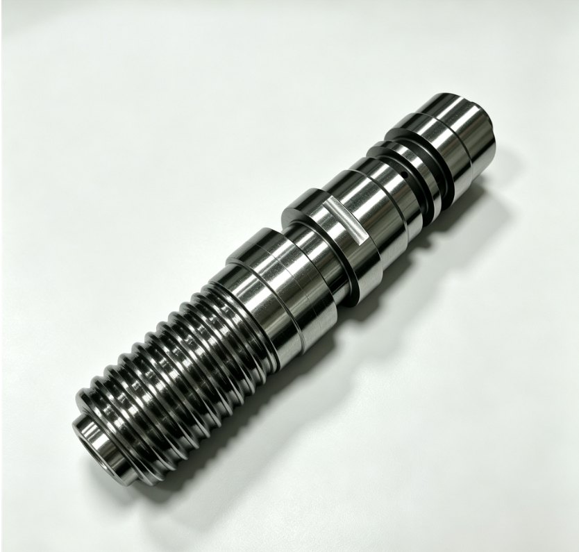
Choix des matériaux : Prévenir le grippage et l’usure
Les systèmes de levage fonctionnent selon les conditions suivantes :
- Haute pression
- température élevée
- contact métal-métal continu
Choisir le mauvais matériau peut entraîner exaspérant, là où les surfaces se soudent et cèdent.
Matériaux recommandés
- Acier à outils H13
- Acier pré-trempé 718H
Guide de dureté
- Cible: 50–54 HRC
- Maintenez la force de levage légèrement supérieure à celle du noyau
Option haute performance
Pour des cycles plus rapides :
- Utiliser Inserts en cuivre béryllium
Avantages:
- Dissipation thermique plus rapide
- Temps de refroidissement réduit
- Amélioration de l'efficacité de la production
3 conseils d'experts pour concevoir un élévateur à toute épreuve
1. Ajouter un guide de « queue »
Toujours soutenir la base de la tige de levage avec un bloc de guidage.
Sans soutien :
- La tige vibre
- Les vibrations provoquent des bavures et de l'usure
2. Utiliser des rainures d'huile
Le frottement est l'ennemi de tout élément mobile.
Meilleures pratiques :
- Ajouter des rainures de lubrification aux surfaces de glissement
Exception:
- Moules médicaux → utiliser un revêtement DLC au lieu d'huile
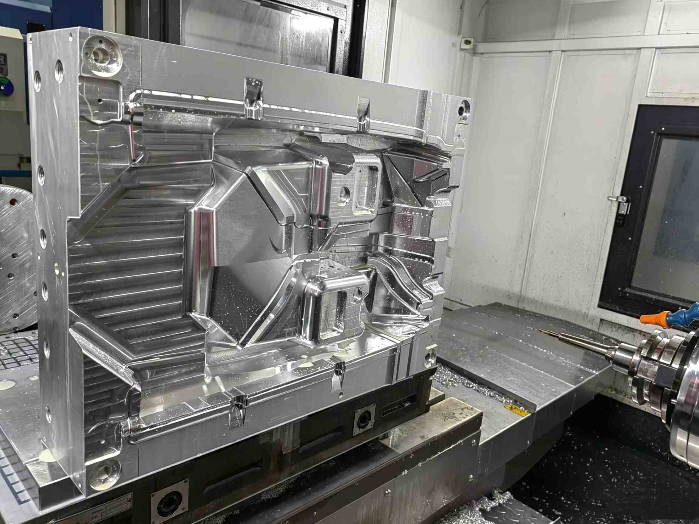
3. Contrôler l'ajustement de la ligne de séparation (PL)
La surface d'arrêt du dispositif de levage doit correspondre parfaitement au noyau.
Même un écart de 0,01 mm peut provoquer :
- Lignes de témoins visibles
- mauvaise qualité de surface
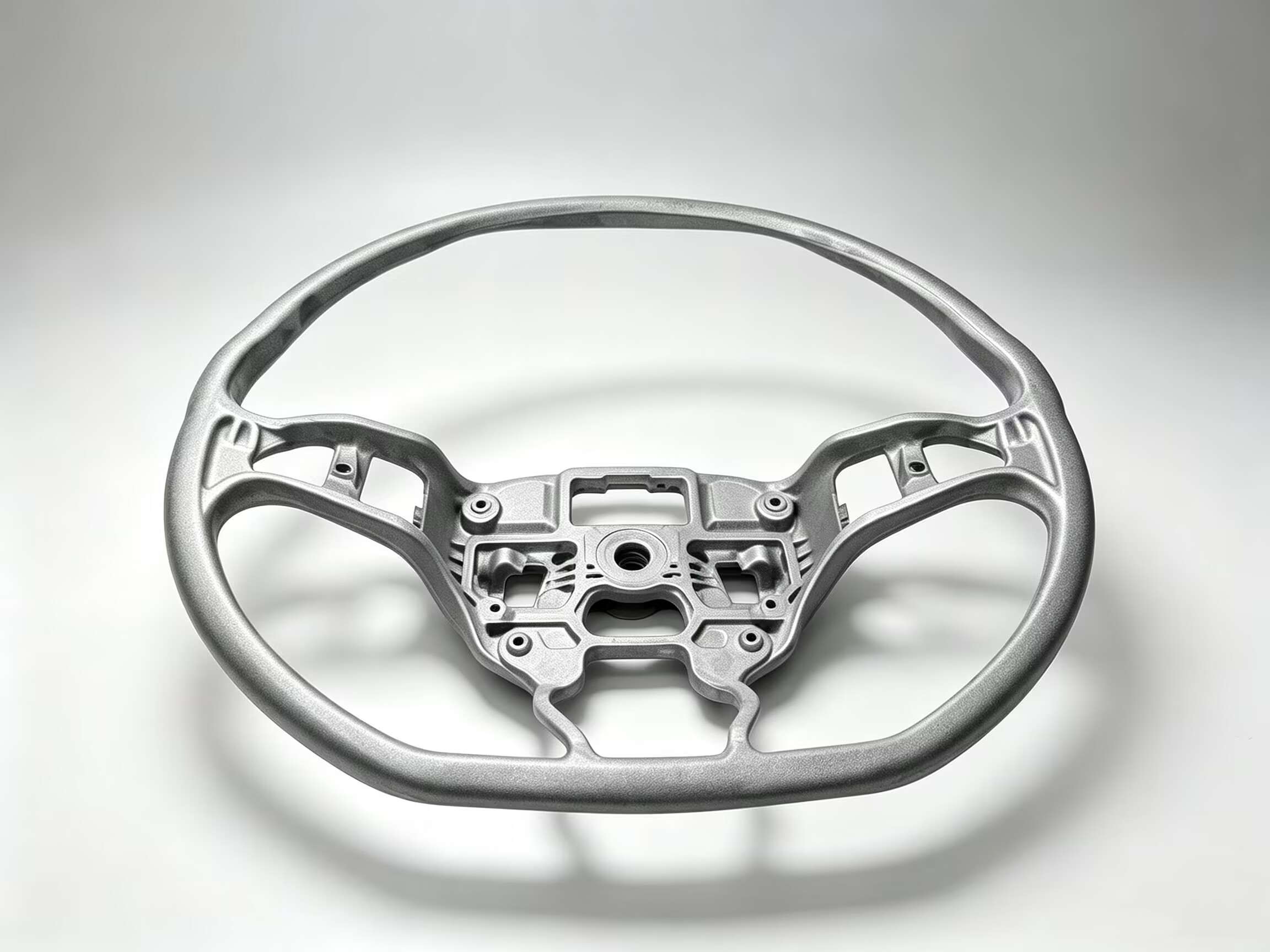
Lifter ou Slider : lequel choisir ?
Le choix entre un poussoir et un coulisseau dépend entièrement de l'emplacement de la contre-dépouille.
Utilisez un curseur lorsque :
- Le contre-dépouille est externe
- Il y a suffisamment d'espace pour les actions latérales
Utilisez un élévateur lorsque :
- Le contre-dépouille est interne
- L'espace est limité.
- Les systèmes hydrauliques ne sont pas pratiques
Réflexions finales
Un dispositif de levage de moule est l'une des solutions les plus efficaces pour les contre-dépouilles internes, mais seulement s'il est correctement conçu.
En contrôlant :
- Angle
- Autorisation de voyage
- sélection des matériaux
- Soutien structurel
Vous pouvez transformer une fonctionnalité à haut risque en une mécanisme fiable et reproductible qui assure le bon fonctionnement de votre chaîne de production.
Besoin d'aide pour optimiser la conception de votre moule ou résoudre des problèmes de contre-dépouilles complexes ?
Visite www.xinkeymould.com pour obtenir un soutien d'experts et améliorer les performances de vos outils.


Nous contacter