
Perché i sottosquadri interni rappresentano un problema serio nello stampaggio a iniezione
-
 Aronna Zheng
- 15 aprile 2026
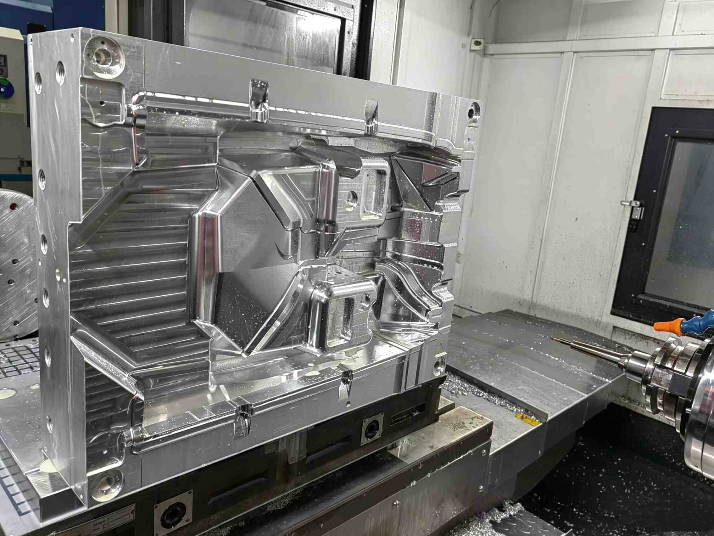
Siamo onesti: i sottosquadri interni sono un incubo per i progettisti di stampi. A differenza delle caratteristiche esterne, non possono essere gestiti con i cursori standard.
Se la geometria non è progettata correttamente, le conseguenze possono essere gravi:
- Parti fissate in modo permanente al nucleo
- Danni o graffi superficiali
- Rottura dell'asta di sollevamento
- Costi elevati tempi di inattività della produzione
Quando si ha a che fare con clip o boss interni, il sollevatore per stampi diventa la soluzione meccanica più affidabile.
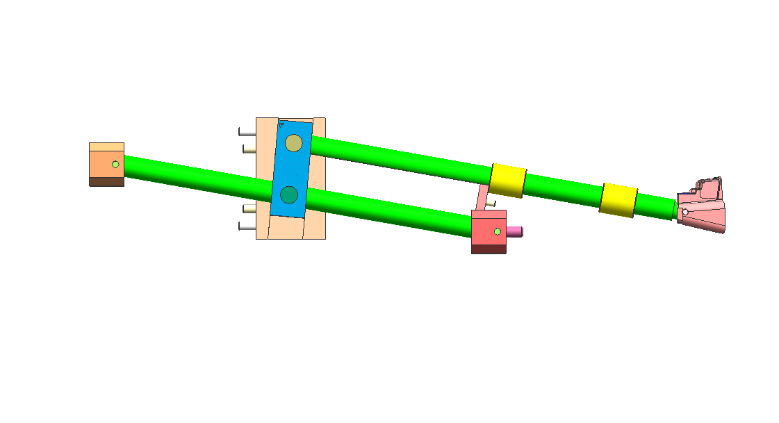
Come funziona un sollevatore per stampi: il principio del "passo laterale".
Un sollevatore per stampi non si muove come un cursore tradizionale. Il suo movimento è invece azionato dal sistema di espulsione.
Durante il ciclo di eiezione:
- Il sollevatore si muove positivamente con la piastra di espulsione
- Allo stesso tempo, segue un percorso angolato
- Ciò crea un combinato movimento verticale + laterale
Questo movimento laterale, spesso chiamato “passo laterale”—è ciò che libera il sottosquadro.
Regola di progettazione fondamentale
Permetti sempre almeno 2 mm di corsa extra oltre la profondità di sottosquadro.
Qualsiasi valore inferiore aumenta il rischio di:
- segni di trascinamento
- Graffi superficiali
- Rilascio incompleto
L'errore più comune: angolo di sollevamento errato
Uno dei più grandi errori di progettazione è quello di rendere l'angolo del sollevatore troppo ripido per risparmiare spazio.
Angolo di sollevamento consigliato
- Intervallo ottimale: 5° – 11°
Zona di rischio
- Sopra i 15°: Alto rischio di legame e di rottura
Ad angolazioni più ripide:
- La forza laterale aumenta in modo significativo
- Il movimento verticale diventa limitato
- Il sollevatore potrebbe incepparsi o l'asta potrebbe piegarsi
Quando gli angoli ripidi sono inevitabili
Se il tuo progetto impone un angolo maggiore, considera:
- Base di sollevamento incernierata
- Design del sollevatore con scanalatura a T
Questi accorgimenti contribuiscono a ridurre lo stress sull'asta di sollevamento e a migliorarne la durata.
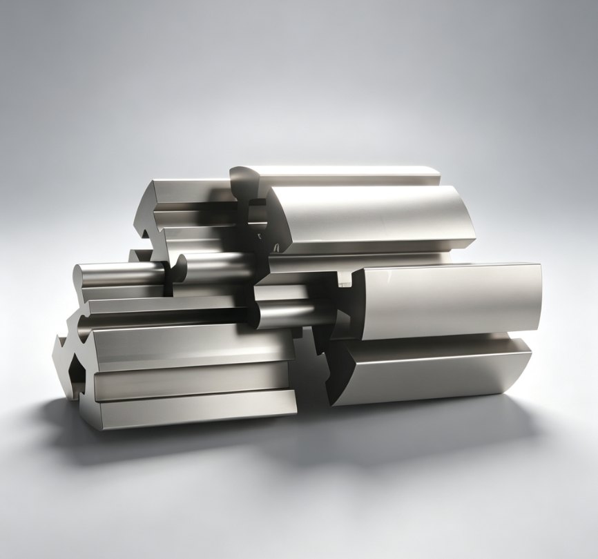
Selezione dei materiali: Previene l'abrasione e l'usura
I sistemi di sollevamento funzionano secondo le seguenti condizioni:
- Alta pressione
- Alta temperatura
- Contatto continuo metallo-metallo
La scelta del materiale sbagliato può portare a irritante, dove le superfici si saldano insieme e si rompono.
Materiali consigliati
- Acciaio per utensili H13
- Acciaio pre-temprato 718H
Linee guida sulla durezza
- Bersaglio: 50–54 HRC
- Mantieni il sollevatore leggermente più duro del core
Opzione ad alte prestazioni
Per cicli di ciclo più rapidi:
- Utilizzo Inserti in rame al berillio
Vantaggi:
- Dissipazione del calore più rapida
- Tempo di raffreddamento ridotto
- Aumento dell'efficienza produttiva
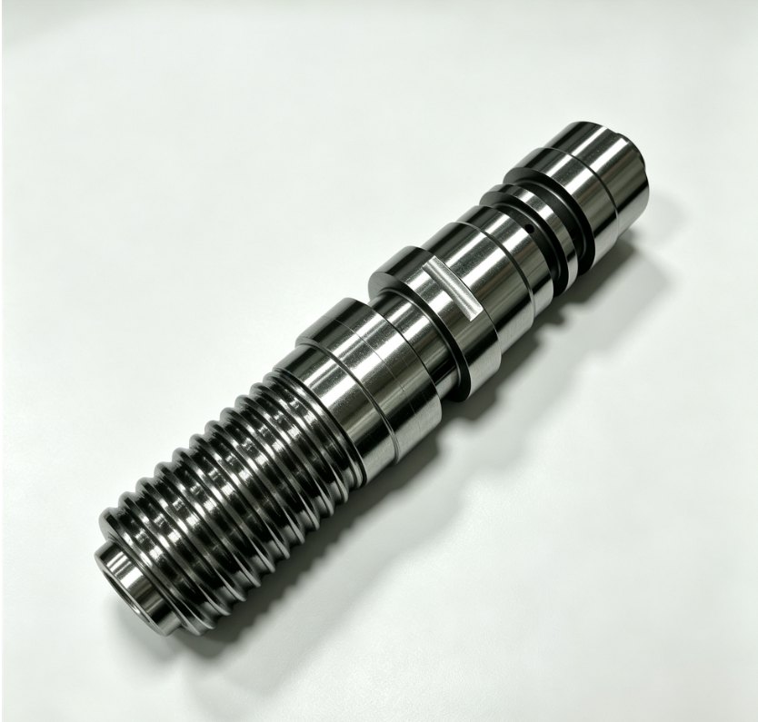
3 consigli di esperti per un design di sollevatore a prova di proiettile
1. Aggiungi una guida “Coda”
Sostenere sempre la parte inferiore dell'asta di sollevamento con un blocco di guida.
Senza supporto:
- L'asta vibra
- Le vibrazioni provocano bagliori e usura
2. Utilizzare scanalature per l'olio
L'attrito è il nemico di qualsiasi componente in movimento.
Buona prassi:
- Aggiungere scanalature di lubrificazione alle superfici di scorrimento
Eccezione:
- Stampi medicali → utilizzare un rivestimento DLC al posto dell'olio
3. Controllare l'adattamento della linea di separazione (PL)
La superficie di chiusura del sollevatore deve adattarsi perfettamente al nucleo.
Anche un spazio di 0,01 mm può causare:
- Linee di testimonianza visibili
- Qualità superficiale scadente
Sollevatore o cursore: quale scegliere?
La scelta tra un sollevatore e uno scorrevole dipende interamente dalla posizione del sottosquadro.
Utilizzare un cursore quando:
- Il sottosquadro è esterno
- C'è abbastanza spazio per le azioni collaterali
Utilizzare un sollevatore quando:
- Il sottosquadro è interno
- Lo spazio è limitato
- I sistemi idraulici non sono pratici
Considerazioni finali
Un sollevatore per stampi è una delle soluzioni più efficienti per i sottosquadri interni, ma solo se progettato correttamente.
Controllando:
- Angolo
- Autorizzazione al viaggio
- Selezione dei materiali
- Supporto strutturale
È possibile trasformare una funzionalità ad alto rischio in una meccanismo affidabile e ripetibile che mantiene la tua linea di produzione in funzione senza intoppi.
Hai bisogno di aiuto per ottimizzare il design del tuo stampo o per risolvere problemi di sottosquadri complessi?
Visita www.xinkeymould.com per ottenere supporto da esperti e migliorare le prestazioni dei vostri utensili.


Contattaci