-
Home

-
Capability
- CNC Machining Parts
- CNC Milling & Turning
CNC Milling & Turning
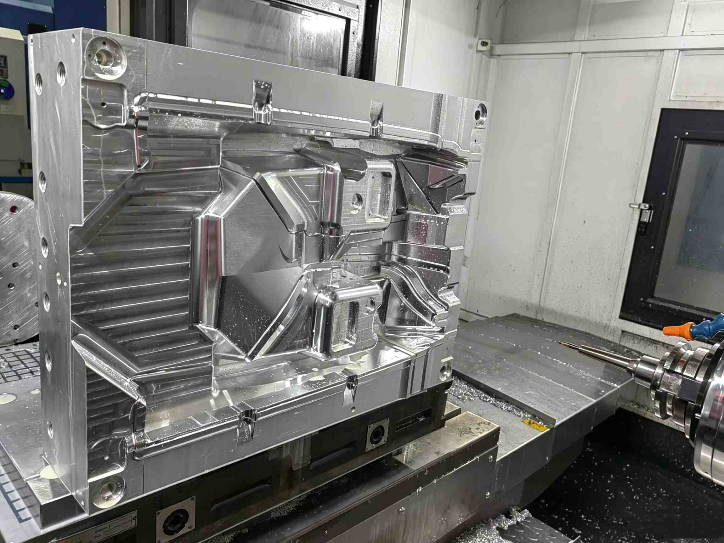
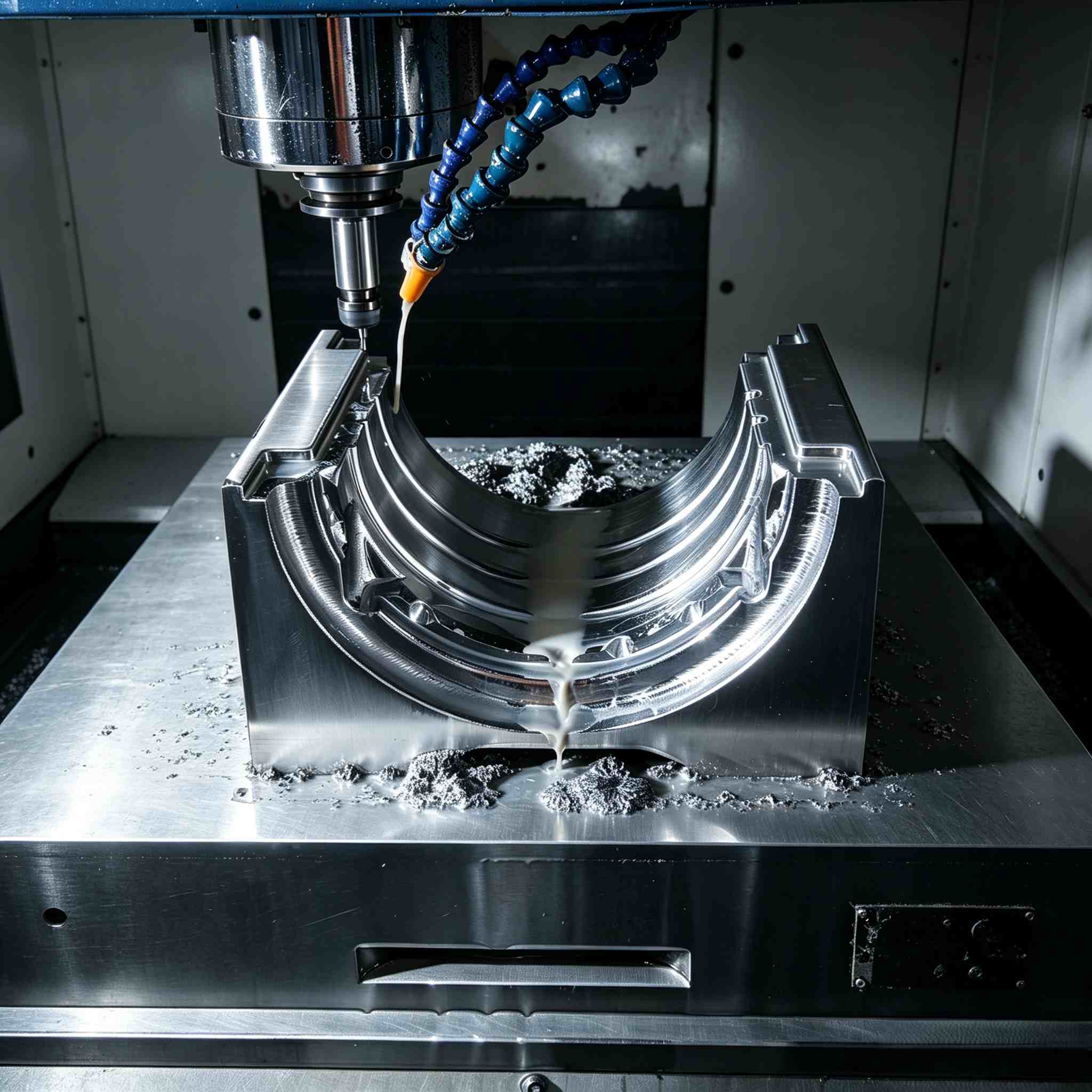
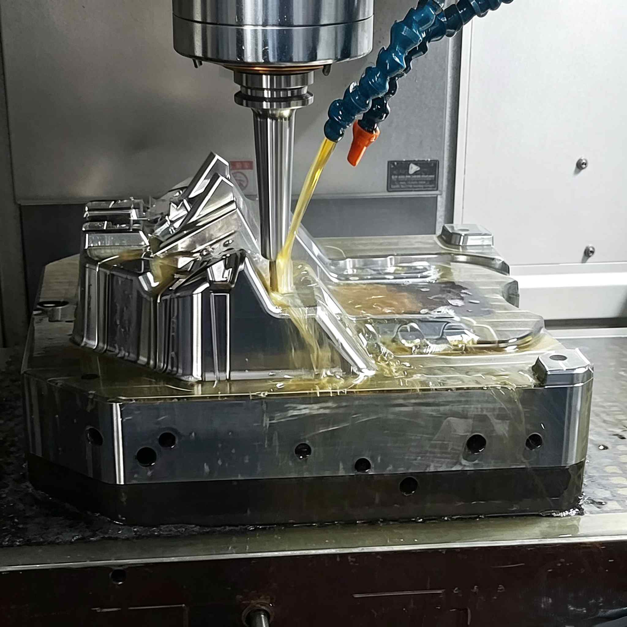
5-axis CNC milling and turning integrates multi-face milling capability with CNC lathe functionality on a single machine platform — typically a 5-axis mill-turn center with a tilting spindle and a turning table, or a multi-tasking machine with both milling spindle and turning turret. The fundamental advantage over separate 3-axis mills and CNC lathes is part-complete machining: a workpiece that requires milled flats, drilled cross-holes, keyways, and threaded bores PLUS turned diameters, threads, grooves, and face details is completed in one or two setups without moving between machines. This eliminates the tolerance stack that accumulates every time a part is re-fixtured — a compound error that can exceed ±0.05mm across four separate mill and lathe setups. At XINKEY MOULD, our 5-axis mill-turn cell handles the full spectrum from simple turned shafts to complex prismatic parts requiring features on five faces plus cylindrical geometry. Every job — from a single prototype to a 10,000-piece production run — starts with a DFM review incorporating 5-axis accessibility analysis, followed by CAM programming with collision-checked toolpath simulation that includes the full machine kinematic model. For parts that don't require full 5-axis simultaneous contouring (see our dedicated 5-Axis CNC Machining page for impellers, 3D surfaces, and undercut geometries), 5-axis mill-turn delivers the fastest, most accurate route from billet to finished component.
- Tolerance down to ±0.02 mm
- 3-axis milling & CNC turning combined
- Ideal for housings, shafts, brackets & jigs
- Full range of materials — metal & plastic
- Fast turnaround for prototypes & low-volume runs
- Product Details
1. What Problems Can This Product Solve?
Tolerance Drift in Aluminum Batch Production
Aluminum 6061-T6 machining generates significant heat; as a batch run progresses through hundreds or thousands of parts, tool wear and thermal expansion in the spindle gradually shift dimensions. A feature that measures in-spec on part #10 may drift 0.03–0.05mm out of tolerance by part #500 if not monitored. XINKEY MOULD implements in-process SPC checks at predefined intervals (every 50–100 parts depending on tolerance criticality), with tool-life management that preemptively replaces tools before wear exceeds the tolerance window. CMM verification on first-article and final-article samples from every batch confirms process stability.
Setup-to-Setup Error Accumulation Across Mill and Lathe Operations
When a part moves from a CNC mill (for flats, holes, keyways) to a CNC lathe (for diameters, threads, grooves), each re-fixturing introduces alignment error. Four setups = four independent error sources, and the final part’s geometric position between a milled bore and a turned diameter can be off by 0.05mm or more even when each individual machine holds ±0.01mm. Standard practice is to oversize stock and remachine mating features — adding cost and lead time. XINKEY MOULD’s 5-axis mill-turn platform completes milling and turning operations on the same machine with the same work coordinate system. The bore and the diameter share the same datum: zero transfer error, zero re-alignment compensation.
Chatter and Surface Finish Degradation on Deep Pockets
Milling deep pockets and thin-walled features — especially in stainless steel and titanium — introduces tool deflection and chatter that degrade surface finish and dimensional accuracy. Standard long-reach end mills amplify vibration when length-to-diameter ratio exceeds 4:1. XINKEY MOULD programs adaptive 5-axis toolpath strategies (trochoidal milling, dynamic roughing) that maintain constant tool engagement angle and reduce radial cutting forces, combining tilted-tool access for better reach with vibration-dampened tool holders for L/D ratios above 5:1.
2. Typical Applications
Pneumatic and Hydraulic Manifold Blocks
Multi-port manifold bodies with intersecting internal channels, threaded ports on multiple faces, and O-ring seal faces requiring perpendicularity across three or more planes. 5-axis single-setup machining ensures all port faces are machined square to their respective axes without cumulative alignment error. Materials: aluminum 6061/7075, stainless steel 316L for corrosive fluid applications.
Bearing Housings, Shafts, and Rotating Mill-Turn Components
Precision bearing seats (H7 tolerance bore) with concentric turned diameters, plus milled mounting flanges, cross-drilled lubrication holes, keyways, and threaded features — all machined with shared datum reference on one 5-axis platform. Surface finish Ra 0.8µm or better on bearing journals. Materials: alloy steel 4140, stainless steel 304/316, aluminum 7075.
Automation and Fixturing Components
Base plates, mounting brackets, sensor holders, gripper fingers, and custom fixture bodies for automated assembly lines. Multi-face machining with compound-angle mounting surfaces completed without re-fixturing. Mixed-material capability — aluminum for lightweight structural parts, steel for wear-resistant guide surfaces — all under one quality plan.
Prototype and Low-Volume Functional Parts
Single-unit prototypes for design validation, functional testing, and fit-check assemblies. 5-axis speed advantage: multi-face parts prototyped in one setup with directly verifiable geometric relationships. Materials: aluminum 6061 for mechanical prototypes, stainless steel 304 for corrosion-resistant testing, POM for snap-fit mechanism testing. Lead time: 3–5 working days.
Consumer Product and Industrial Equipment Components
Camera body shells, drone motor mounts, bicycle components, coffee machine brew group parts, and handheld device enclosures. Anodized aluminum finishing for consumer-facing surfaces; bead-blasted matte or brushed metal finishes on request. 5-axis mill-turn handles complex outer profiles plus precision bores in a single fixturing.
3. Specification Table
| Item | Details |
| Process Capability | 5-axis CNC milling, CNC turning, and 5-axis mill-turn combined machining |
| Work Envelope (Milling) | Ø500 × 400mm typical; 5-axis positioning for multi-face access without re-fixturing |
| Work Envelope (Turning) | Ø300 × 500mm; bar-fed Ø65mm |
| Standard Tolerance | ±0.01mm for milling and mill-turn operations; ±0.005mm for turning (cylindrical features) |
| Achievable Tolerance | ±0.005mm on request (with additional inspection and process cost) |
| Surface Finish (As-Machined) | Ra 0.8–1.6µm standard; Ra 0.4µm achievable on finishing passes with optimized toolpath |
| Material Range | Aluminum (6061, 7075, 5083, 2024), stainless steel (304, 316L, 303, 17-4PH), alloy steel (4140, 4340), brass, copper, titanium (Grade 2, Grade 5), POM, nylon (PA6, PA66), PEEK, PTFE, PC, ABS |
| Part Size Range | 5mm – 500mm (milling); Ø3mm – Ø300mm (turning) |
| Batch Size | 1 pc prototype to 50,000 pcs serial production |
| Lead Time (Prototype) | 3–5 working days for single parts; 5–7 days for multi-part assemblies |
| Lead Time (Production) | 7–10 days for ≤500 pcs; 10–15 days for 500–5,000 pcs; project-specific above 5,000 pcs |
| Quality Control | CMM dimensional report on first article and batch sample; surface roughness tester; thread gauge verification; SPC in-process checks on production runs; in-machine probing for datum verification between operations |
| Finishing Options | Anodizing (clear, black, color), hard anodizing, bead blasting, brushing, powder coating, electroless nickel plating, passivation (stainless steel) |
| Design File Formats | STEP, IGES, X_T (Parasolid); 2D PDF drawing with tolerances and surface finish callouts |
4. Project Process & Quality Control
Phase 1: DFM Review & 5-Axis CAM Programming
Action:Review 3D CAD for 5-axis mill-turn machinability: multi-face feature accessibility, minimum internal radii, tool reach with tilted tool-axis, thin-wall feasibility. Define single-setup strategy — which operations run under the milling spindle, which under the turning mode. Generate 5-axis CAM toolpaths with collision-checked machine simulation including full kinematic model.
QC Focus:DFM report: 5-axis accessibility analysis, recommended setup strategy, estimated cycle time with mill-turn integration benefit quantified. CAM simulation verified: zero collisions, toolpath covers all features, turning and milling coordinate systems aligned.
Phase 2: Material Preparation & Machine Setup
Action:Source certified material stock per specification — mill certificates provided. Cut stock with machining allowance. Single fixturing setup for mill-turn sequence. Probe workpiece to establish work coordinate system common to both milling and turning operations. Load tool library for milling spindle and turning turret; laser-measure all tool lengths.
QC Focus:Material cert check: alloy grade, temper, lot traceability. Workpiece alignment: probe runout ≤0.01mm. Tool measurement: all tools within ±0.01mm of programmed value. Milling spindle and turning turret offsets verified.
Phase 3: Turned Feature Machining & 5-Axis Roughing
Action:Execute turning operations: face, turn OD, bore ID, cut threads and grooves. Then switch to 5-axis milling mode: rough out prismatic features using 3+2 positioning at optimal compound angles for each face. Leave 0.2–0.5mm stock for finishing. Intermediate probe check on reference datums to verify no workpiece shift between turning and milling phases.
QC Focus:In-process probe check: datum features stable within 0.01mm after turning phase. Post-roughing measurement: stock remaining 0.2–0.5mm uniform. Thread gauge check: Go/No-Go on turned threads. Insert condition check — replace if flank wear exceeds 0.2mm.
Phase 4: 5-Axis Finish Machining & Deburring
Action:Execute 5-axis finishing passes: tilted-tool finishing for improved surface quality on angled faces, reduced depth of cut (0.05–0.15mm), optimized spindle speed and feed for target Ra. Thread milling for precision threads, engraving per specification. Manual and vibratory deburring to remove sharp edges.
QC Focus:CMM dimensional check on all critical features — both milled and turned — against same datum reference. Surface roughness measurement on marked surfaces. Thread gauge check (Go/No-Go) on all threaded features. Visual inspection: no burrs, no tool marks, consistent finish across milled and turned surfaces.
Phase 5: Surface Treatment & Final QC
Action:Coordinate surface treatment: anodizing, plating, powder coating, passivation. Post-treatment dimensional check to account for coating thickness. Final cleaning and protective packaging.
QC Focus:Post-treatment CMM on critical dimensions (accounting for coating buildup). Coating thickness measurement. Salt-spray test on plated parts where specified. Final visual inspection: uniform surface finish, no handling damage. Shipment with dimensional report, material certs, and process inspection records.
5. Why Choose XINKEY MOULD
CMM Report Standard on Every Production Batch
We don’t ship a declaration of conformance and hope the parts fit. Every production run includes a CMM dimensional report on first-article and batch-sample parts — critical dimensions measured against your drawing tolerance, with deviation recorded. For serial production, SPC control charts track process stability over the full run. You know the parts are within spec before they arrive.
Material Traceability From Stock to Shipment
All metal stock is purchased from ISO-certified mills with mill test certificates (MTC) that trace back to the heat lot. Material certs are included in the shipment documentation. For regulated industries (medical, aerospace, automotive), full material and process traceability is maintained throughout the machining and finishing process.
No MOQ — Prototype or Production, Same 5-Axis Engineering Rigor
Many precision machine shops set a minimum order quantity because setup cost exceeds part value at low volumes. XINKEY MOULD accepts single-piece prototypes with the same DFM, 5-axis CAM, and inspection process applied to 10,000-piece orders. The engineering doesn’t scale down — only the batch size does. Prototype customers often transition to production with us because the process is already proven on the same 5-axis platform.
6. FAQ
Q1: What tolerance can you guarantee on 5-axis mill-turn parts?
Standard tolerance is ±0.01mm for milling/mill-turn operations and ±0.005mm for cylindrical turning features. Because milling and turning share the same datum on our 5-axis platform, true geometric position between milled and turned features is maintained without the re-fixturing error that separates mill-and-lathe shops. Tighter tolerances are achievable — discuss during quotation.
Q2: I have both milled and turned features — will the part go between different machines?
No. Our 5-axis mill-turn center completes milling and turning operations on one machine with one work coordinate system. The part doesn’t leave the fixture between operations — the bore, the cross-hole, the keyway, the thread, and the diameter all reference the same datum. No handoff, no re-alignment, no tolerance mismatch at mating features. For parts that also require complex 3D freeform contouring (impellers, turbine blades, mold cavities), we may route to our dedicated 5-axis simultaneous machining cell — we’ll advise during DFM.
Q3: What’s the minimum order quantity?
One piece. We accept single prototypes for design validation, small batches for pilot production, and serial runs up to 50,000 pieces. Prototype pricing is higher per piece than production pricing due to setup cost, but there’s no minimum to start.
Q4: How fast is prototype delivery?
Single-part prototypes ship in 3–5 working days from order and drawing confirmation. Multi-part assemblies (e.g., 5–15 unique parts) typically ship in 7–10 working days. Express service (2–3 days) is available for urgent projects — subject to machine capacity and material availability.
Q5: Can you source materials, or should I send my own stock?
We source all standard metals and plastics from certified mills and distributors — mill certificates included at shipment. If you require a specific material source or have existing approved stock, you can provide material and we’ll machine from your supplied stock. Just specify during quotation.
Q6: Do you offer surface finishing in-house?
We coordinate surface finishing through qualified partner facilities under our quality plan — anodizing (clear, black, color), hard anodizing, bead blasting, powder coating, electroless nickel plating, and stainless steel passivation. Post-finishing dimensional check ensures coating thickness doesn’t push features out of tolerance. Single-point responsibility: one contact manages machining through finishing.
Q7: What file formats do you need for a quotation?
3D CAD in STEP or IGES format, plus a 2D PDF drawing with dimensions, tolerances, thread specifications, surface finish callouts, and material grade. Also helpful: quantity, surface treatment requirements, and target lead time. We typically return quotations within 24–48 hours.
Q8: What’s the difference between 5-Axis Mill-Turn and 5-Axis CNC Machining at XINKEY MOULD?
5-Axis Mill-Turn (this page) is our production workhorse — it combines turning and multi-face milling on one platform, ideal for parts with both cylindrical geometry and prismatic features: shafts with keyways, manifolds with threaded ports on multiple faces, bearing housings with turned bores and milled flanges. 5-Axis CNC Machining (separate page) is our complex geometry specialist — it handles impellers, turbine blades, 3D mold cavity surfaces, and undercut features requiring full simultaneous 5-axis contouring. We’ll recommend the optimal process for your part during DFM.
Products
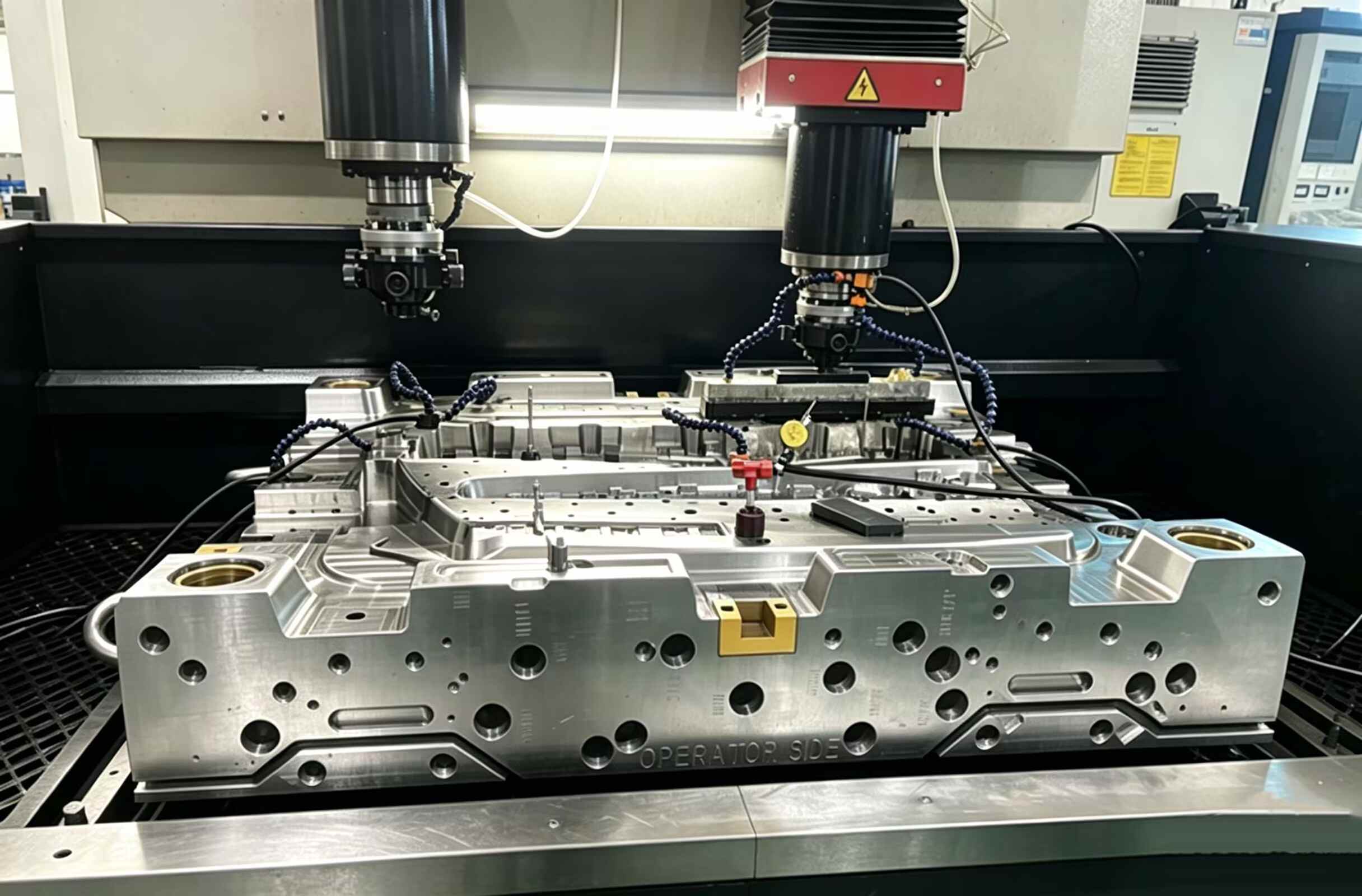
Wire Cut
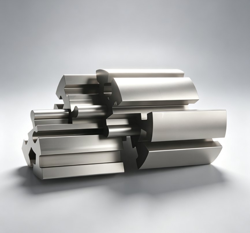
Wire Cut EDM — Precision wire electrical discharge machining for complex 2D profiles, tight-tolerance die components, and hardened steel parts that cannot be milled. Achieves ±0.003mm accuracy and Ra 0.2µm surface finish on tool steel, carbide, and conductive hard metals. Core service for injection mold inserts, stamping die components, and precision gauge tooling.
Learn More
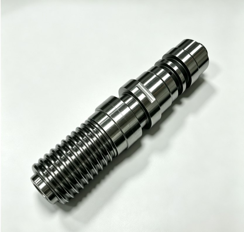
5-Axis CNC Machining
5-Axis CNC Machining — Simultaneous 5-axis contouring for complex 3D surfaces, undercut geometries, and multi-sided parts in a single setup. Eliminates multiple fixturing operations and cumulative tolerance error. Ideal for impellers, turbine blades, orthopedic implants, and injection mold 3D cavity surfaces.
Learn More
EDM Spark Erosion
EDM Spark Erosion — Sinker EDM precision cavity machining for sharp internal corners, deep ribs, and complex 3D geometries in hardened tool steel. Uses custom-machined graphite or copper electrodes to erode features that rotating cutting tools cannot reach. Core process for injection mold cavities, die casting tooling, and blind-pocket features requiring ±0.005mm accuracy.
Learn More
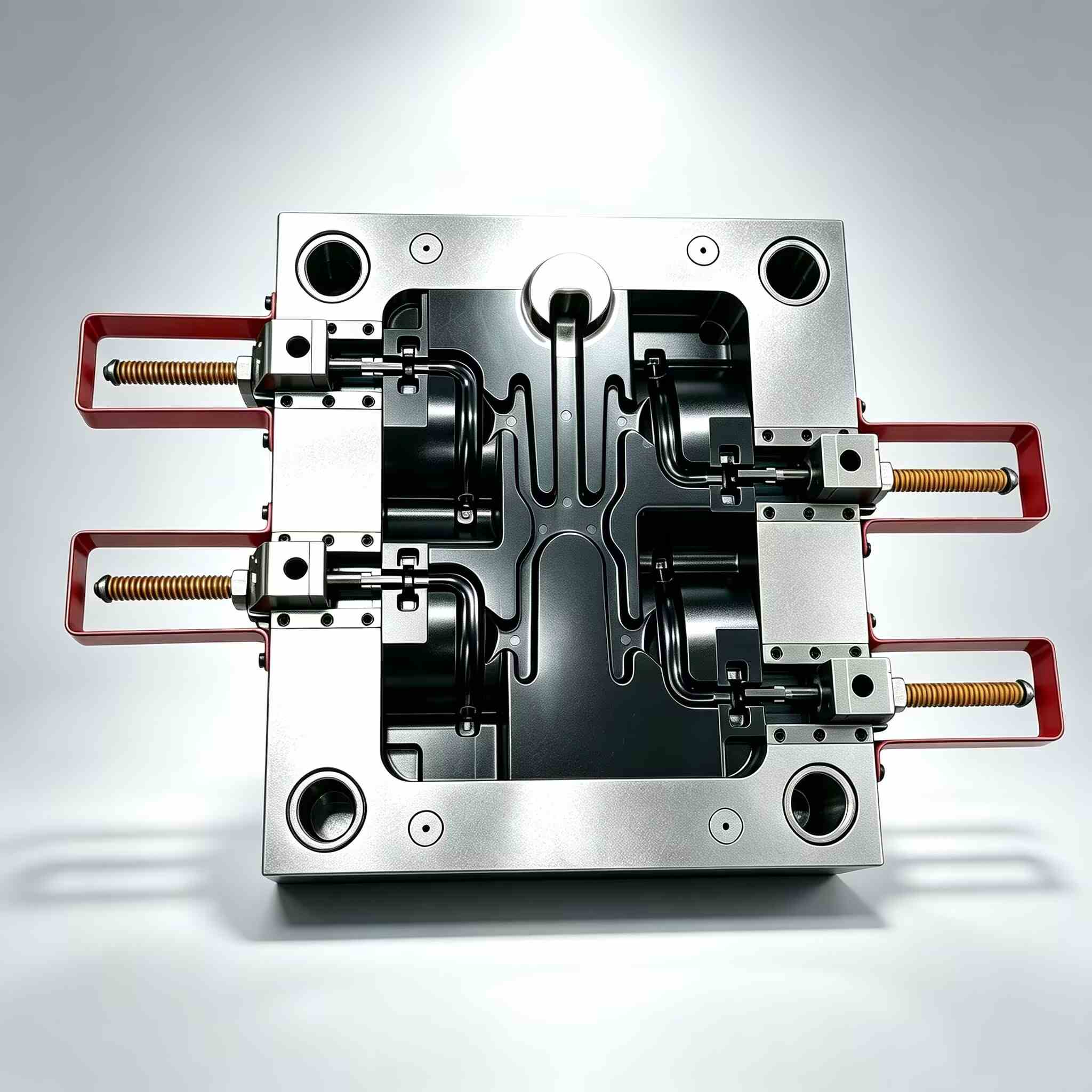
Zinc Die Casting Mold & Parts
Zinc Die Casting Mold — Hot-chamber precision tooling for high-speed zinc alloy components. Designed for thin-wall, net-shape production of automotive trim, electronic housings, and consumer hardware at cycle times as fast as 3-5 seconds with consistent as-cast surface quality.
Learn More
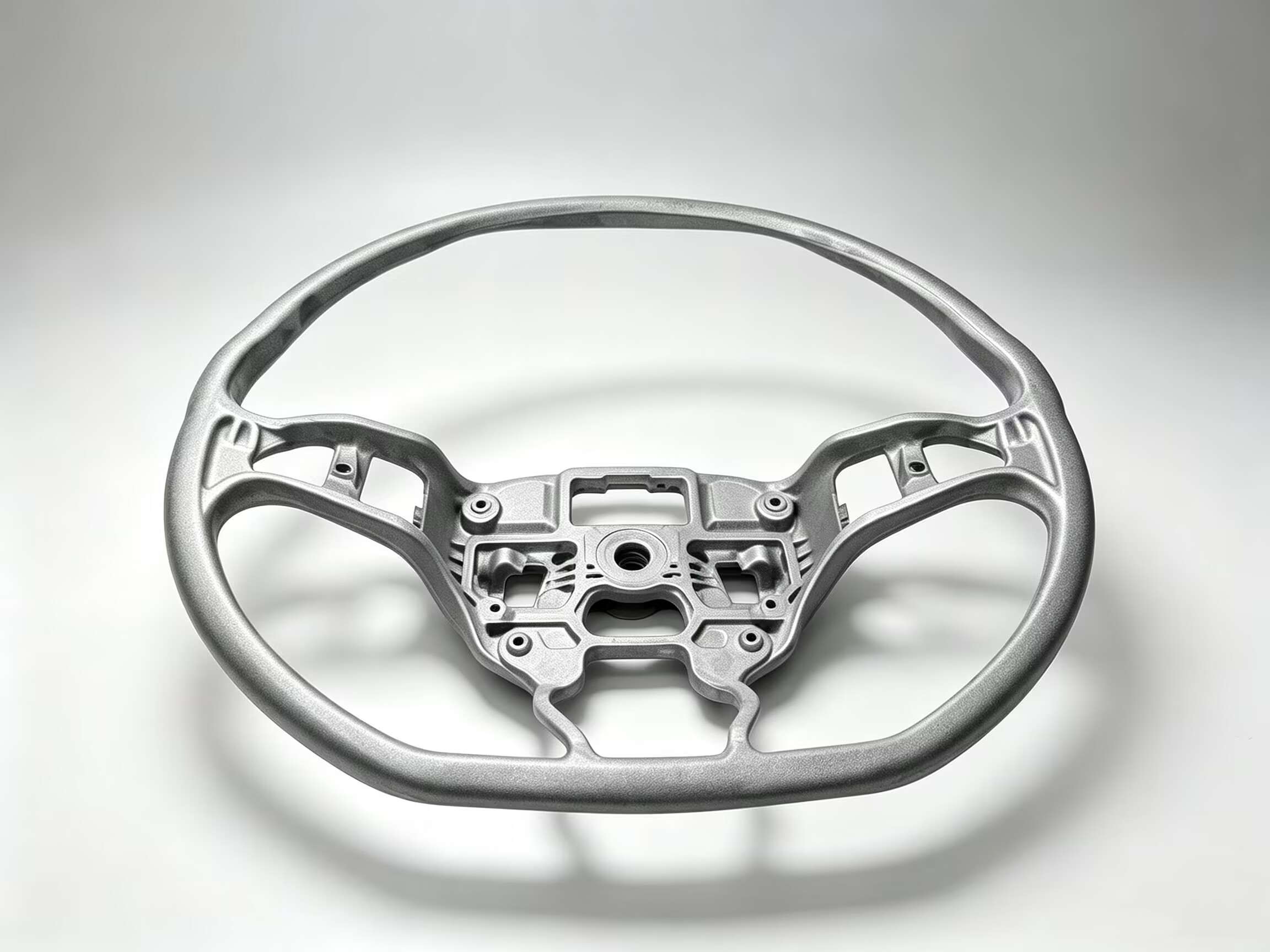
Magnesium Die Casting Mold & Parts
Magnesium Die Casting Mold — Cold-chamber high-pressure tooling engineered for AZ91D, AM60B, and AS41B magnesium alloys. Purpose-built for automotive lightweighting, aerospace housings, and portable electronics where every gram counts. Delivers net-shape components at 1.8 g/cm³ — 33% lighter than aluminum and 75% lighter than steel.
Learn More
Aluminum Die Casting Mold & Parts
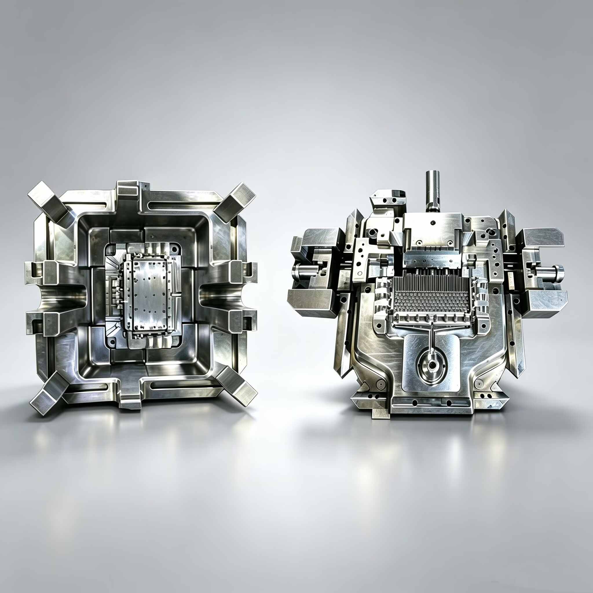
Aluminum Die Casting Mold — Cold-chamber high-pressure tooling for A380, ADC12, A360, and AlSi10MnMg alloys. Engineered for automotive powertrain, structural chassis components, LED lighting, and industrial equipment housings. Standard mold life 300K–500K shots with H13 ESR steel, extendable to 500K+ with advanced PVD coating and vacuum heat treatment.
Learn More
Latest News
- 29th May 2026
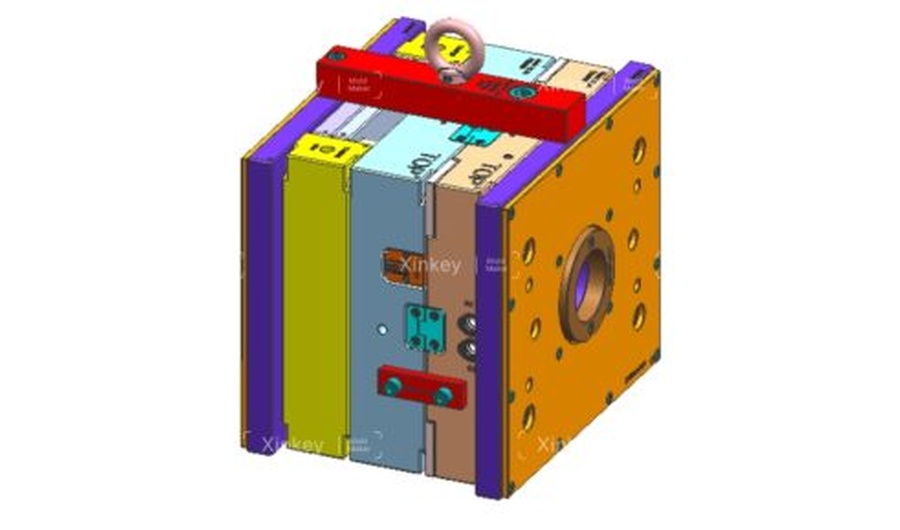
Why Product Development Teams Often Run Into Mold Problems — And How to Prevent Expensive Delays
In a lot of product development projects, most of the attention goes into the product itself — the appearance, functionality, electronics, and user experience.
That part usually moves fast.
The real problems often start later, when the design enters tooling and production.
The reason is simple:
Most product engineers are not mold engineers.
They may understand the product itself very well, but lack experience in injection mold structure design, tooling feasibility, and production-oriented plastic part optimization. As a result, many new products run into the same issues:
Product structures that are difficult to mold
Excessive undercuts and poor draft design
Sink marks and deformation after molding
Filling imbalance and short shots
Difficult mold release
Multiple mold modifications after T1 testing
Delayed product launch schedules
Rising tooling and development costs
In many cases, the mold becomes a troubleshooting process instead of a manufacturing solution.
That is exactly where professional mold engineering support becomes critical.
One-Stop Mold Engineering & Manufacturing Support
We provide a complete one-stop solution covering:
Product structure optimization
DFM analysis
Mold flow simulation
Full mold design
Mold manufacturing and trial molding
By combining product engineering and mold manufacturing into one integrated workflow, we help customers reduce development risks and move products into production faster.
1. Product Structure Optimization for Mass Production
A product design that looks good on the screen does not always work well in real production.
Many plastic parts are initially designed without considering:
Wall thickness consistency
Draft angle requirements
Rib structure limitations
Undercut feasibility
Gate position influence
Cooling deformation risks
These issues may not appear during CAD design, but they quickly become expensive during tooling and trial molding.
Our engineering team reviews the product structure before mold design begins.
Without changing the product appearance or functional requirements, we optimize the structure for injection molding production. This helps prevent common molding problems such as:
Sink marks
Drag marks
Warpage
Short shots
Stress marks
Poor demolding
Early optimization significantly reduces tooling rework and improves first-shot success rates.
2. Professional DFM Analysis (Design for Manufacturability)
Before tooling starts, we provide a complete English DFM report to help customers fully understand the manufacturability of the product.
The report includes:
Parting line suggestions
Gate location recommendations
Potential undercut analysis
Draft angle review
Risk areas for molding defects
Mold structure recommendations
Initial tooling concept proposals
Instead of discovering problems after steel cutting, customers can identify risks early and make informed decisions before production begins.
This shortens communication cycles and keeps project risks under control.
For overseas customers, especially startups and hardware companies without an internal mold engineering team, DFM analysis becomes an important bridge between product design and real manufacturing.
3. Mold Flow Analysis Before Tooling
One of the most expensive mistakes in mold manufacturing is discovering production defects after the mold is already built.
To avoid this, we perform mold flow simulation before tooling production.
Using injection molding simulation software, we can predict issues such as:
Weld lines
Air traps
Filling imbalance
Warpage
Cooling problems
Injection pressure risks
This allows us to optimize both the product structure and mold design before machining begins.
In many projects, mold flow analysis helps reduce repeated mold modifications and lowers the number of trial runs required.
For complex plastic parts, this step can save weeks of development time and significantly reduce overall tooling costs.
4. Full Standardized Mold Design Based on European Standards
A stable mold does not depend only on machining quality. The mold design itself determines long-term reliability.
Our mold design process follows European mold standards including:
HASCO standards
Meusburger standards
We provide complete mold engineering design including:
Parting structure design
Slider and lifter mechanisms
Hot runner systems
Cooling system layout
Ejection system design
Mold assembly structure
3D mold assembly files
2D machining drawings
Complete BOM lists
All drawings are standardized for efficient manufacturing, future maintenance, and long-term production stability.
This is especially important for customers requiring export-quality tooling and consistent production standards.
5. Mold Manufacturing, Trial Molding & Turnkey Delivery
Design alone is not enough.
A successful mold project also depends heavily on machining accuracy, assembly experience, and trial molding capability.
With our in-house mold manufacturing facility, we provide complete tooling production services including:
CNC machining
EDM processing
Mold assembly
Trial molding
Mold correction and optimization
Small batch production support
Customers do not need to coordinate with multiple suppliers for design, machining, testing, and modification.
Everything is managed through one integrated team.
This greatly improves communication efficiency and shortens overall project lead time.
Why Many Companies Choose External Mold Engineering Support
Many startups, product design firms, and small-to-medium hardware companies do not have an internal mold engineering department.
As a result, product teams often face challenges such as:
Not knowing whether the product can actually be molded
Difficulty evaluating mold supplier proposals
Repeated tooling modifications
Unclear root causes during testing
Long development delays
By working with an experienced mold engineering and manufacturing partner, these problems can be solved much earlier in the process.
We act as an external mold engineering extension of your development team — combining product optimization, mold engineering, and manufacturing into one complete workflow.
The Real Value of Integrated Mold Engineering
A good mold supplier does more than simply manufacture steel.
The real value comes from helping customers avoid manufacturing mistakes before they happen.
With integrated engineering and manufacturing support, companies can:
Reduce tooling risks
Shorten product development cycles
Improve first mold trial success rates
Lower modification costs
Accelerate mass production readiness
Achieve stable long-term production quality
For companies targeting European and international markets, standardized mold engineering is not just a quality advantage — it directly affects production stability, delivery timelines, and total project cost.
Looking for Injection Mold Engineering Support?
When developing new plastic products, many teams find themselves without sufficient in-house mold engineering capabilities — and that’s where we come in.
We offer a full range of one-stop injection molding services to guarantee smooth mass production. Our support spans every key stage: product optimization, DFM analysis, mold design and fabrication, as well as ongoing production assistance.
- 18th May 2026
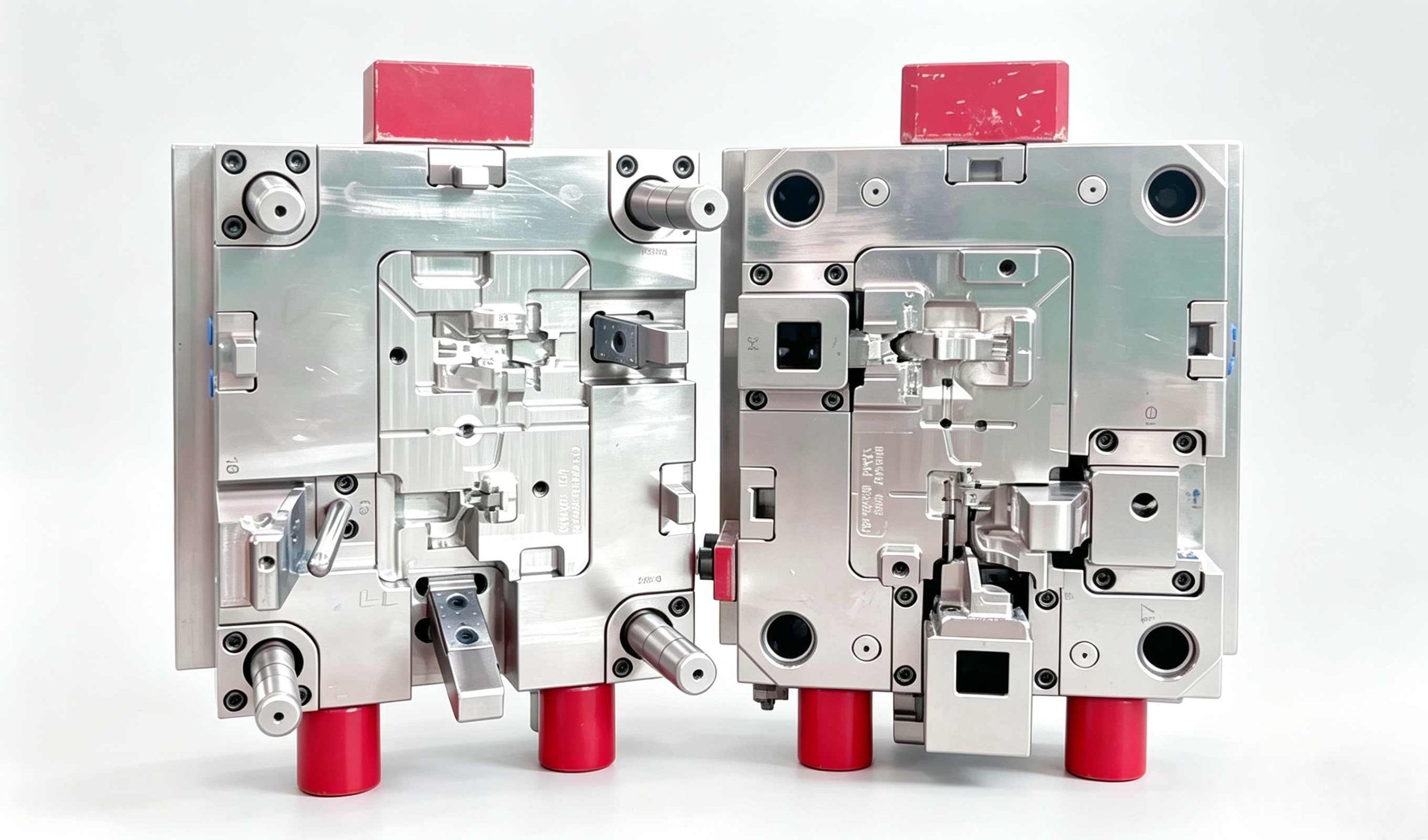
Beyond the Wave: How to Kill Flow Marks and Save Your Surface Finish
Flow marks in injection molding | Causes, troubleshooting, and prevention methods for improving cosmetic part quality
Let’s be honest: nothing kills a production run faster than flow marks.
You can have a part that hits every dimensional spec and fills perfectly, but if the surface is covered in wavy lines or ugly streaks, it’s headed straight for the scrap bin. In industries like automotive or consumer electronics, where “cosmetics” are everything, these ghost-like patterns are a total deal-breaker.
The most frustrating part? Flow marks are usually purely aesthetic. The part is structurally sound, yet it’s still a “reject” in the eyes of the client. If you’re tired of seeing your profit margins disappear into a pile of cosmetic scrap, you need to understand exactly why your melt front is struggling inside the tool.
What’s Actually Happening Inside the Cavity?
At its core, a flow mark is a permanent record of a “hesitant” melt front.
Think of the melt front as it hits the tool: that outer “skin” is in a constant race against the cold steel of the mold. If your flow is too sluggish or the heat isn’t there to back it up, that leading edge won’t glide—it “stutters.”
When the hotter resin behind it finally shoves forward, it leaves a permanent scar on the surface. That wavy line or ring-like pattern you’re seeing is essentially a visual map of a flow that was fighting for every inch.
It isn’t just an ugly defect; it’s a smoking gun that proves your material is losing the battle against the temperature of your tool.
In our experience, you’ll almost always find these marks in the same few trouble spots.
Common Flow Mark Locations
In most cases, flow marks appear near:
Gate areas
Thin-to-thick wall transitions
Sharp corners
Long flow paths
Areas with sudden flow direction changes
What Flow Marks Can Look Like
Depending on the material and mold structure, the defect may look like:
Ripple lines
Halo rings
Snake-like streaks
Gloss differences
Shadow marks
On glossy or dark-colored parts, flow marks are usually easier to notice.
Why Do Flow Marks Happen?
Everything in the press hinges on a delicate balance between how the melt flows and how the tool cools. The second that resin starts dragging or cooling down before it’s supposed to, you’re going to see the evidence in the surface finish immediately.
1. The Culprit: Sluggish Injection Speed
Usually, the first place we look is the fill speed.
If your injection is too slow, you’re basically losing a race against time. That leading edge of the plastic starts to stall out and firm up while the hotter material behind it is still trying to shove its way forward.
This creates a “stutter” effect at the flow front, leaving those tell-tale wavy ripples scarred into the surface of your part.
This is especially common in:
Thin-wall parts
Large flat surfaces
Long-flow molds
Solution
Increase injection speed gradually
Use multi-stage injection control
Maintain stable filling pressure
A faster and smoother filling process often reduces visible flow patterns significantly.
2. Melt Temperature Is Too Low
If the material temperature is insufficient, resin viscosity increases and flow resistance becomes higher. The melt cannot maintain a smooth surface while traveling through the cavity.
Low melt temperature often causes:
Uneven flow fronts
Surface streaking
Poor gloss consistency
Solution
Increase barrel temperature carefully
Verify actual melt temperature instead of only machine settings
Follow the resin supplier’s recommended processing range
Different materials react differently to heat. Engineering plastics usually require tighter temperature control than commodity resins.
3. Mold Temperature Is Too Cold
A cold mold surface causes the melt to freeze rapidly once it touches the cavity wall. The skin layer forms too early, interrupting smooth resin flow.
This issue commonly appears in winter production or molds with poor cooling balance.
Solution
Raise mold temperature
Improve temperature consistency between cavity sections
Use mold temperature controllers if necessary
For cosmetic parts, stable mold temperature is often more important than cycle speed.
4. Gate Design Problems
The gate is essentially the “throat” of your tool.
If it’s too tight or sitting in the wrong spot, the resin won’t glide into the cavity—it’ll stumble, creating a chaotic and unstable flow. Even worse, undersized gates act like high-pressure nozzles that “beat up” the material with excessive shear stress, leaving behind those nasty streaks that ruin your surface finish.
Common Gate-Related Issues
Gate too small
Incorrect gate position
Single gate on large parts
Sudden flow expansion after the gate
Solution
Increase gate size if possible
Relocate the gate to improve flow balance
Use multiple gates for larger parts
Optimize runner layout
Proper gate design improves both filling stability and cosmetic quality.
5. Wall Thickness Changes Too Quickly
When the melt flows from a thin section into a thicker area, the flow speed changes suddenly. This transition can disturb the surface appearance and leave visible flow lines.
Abrupt wall changes also increase cooling inconsistency.
Solution
Maintain uniform wall thickness
Use gradual transitions instead of sharp thickness jumps
Add proper radii to flow areas
Good part design reduces many molding defects before production even begins.
6. Poor Venting Inside the Mold
Trapped gas inside the cavity can interfere with melt flow. As air becomes compressed, the plastic front may hesitate or change direction slightly, leaving surface defects behind.
Although venting issues are more commonly linked to burn marks, they can also contribute to flow marks.
Solution
Clean blocked vents
Add additional venting where needed
Improve gas escape near end-of-fill areas
Proper venting supports smoother material flow throughout the cavity.
7. Material Moisture or Resin Problems
Some engineering plastics absorb moisture from the air quickly. Wet material can create unstable melt behavior during injection, affecting surface quality.
Inconsistent regrind ratios or contaminated resin may also increase flow defects.
Solution
Dry hygroscopic materials correctly
Monitor moisture levels
Keep material batches consistent
Reduce contamination risk during handling
Stable material quality is essential for stable molding results.
How to Troubleshoot Flow Marks Efficiently
When flow marks appear, avoid changing multiple parameters at once. Random adjustments usually make troubleshooting harder.
A better approach is to check the process step by step:
Confirm melt temperature
Verify mold temperature balance
Increase injection speed gradually
Check gate and runner condition
Inspect venting areas
Review wall thickness design
Evaluate resin condition
Process records from previous stable production runs can also help identify changes faster.
How to Prevent Flow Marks During Mold Design
Prevention is always cheaper than correction. Many flow mark problems begin during part design or mold development.
Recommended Design Practices
Use balanced runner systems
Maintain uniform wall thickness
Avoid excessive flow length
Design proper venting locations
Optimize gate position early
Consider cosmetic requirements during mold flow analysis
When aesthetics are non-negotiable, you’ve got to get ahead of the problem. Running a mold flow simulation early on isn’t just a luxury—it’s the best way to catch these surface headaches before you ever cut steel.
Trust me, it’s always cheaper to tweak a design on a screen than it is to weld and re-machine a hardened tool once it’s already on the floor.
The Reality: Don’t Just Settle for Scuff Marks
It’s tempting to brush off a flow mark as “just cosmetic,” but that’s a dangerous game. Those wavy patterns are usually the smoking gun of a process that’s fundamentally out of sync.
Whether you’ve got a temperature mismatch or a gate that’s just too tight, letting these “ghosts” haunt your parts is a surefire way to kill your margins with a mountain of rejected scrap.
The truth is, you’re never going to fix a surface issue by just turning one random dial on the press. Real quality is an all-or-nothing deal—you need the tool design, the fill balance, and the heat to all work in harmony.
Stop the guesswork, hunt down the actual root cause, and quit the “firefighting” once and for all.
That’s how you get back to stable, profitable production.
- 11th May 2026
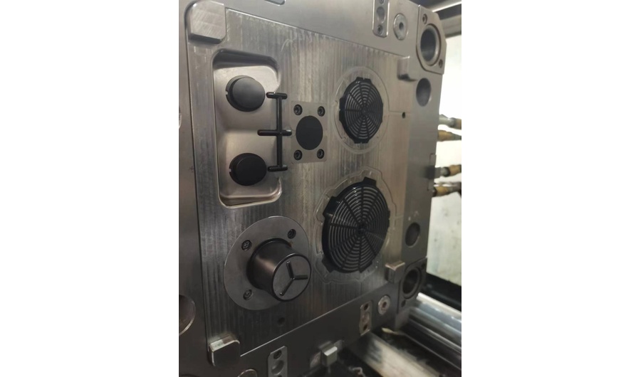
Injection Mold Short Shot Troubleshooting Guide
Introduction
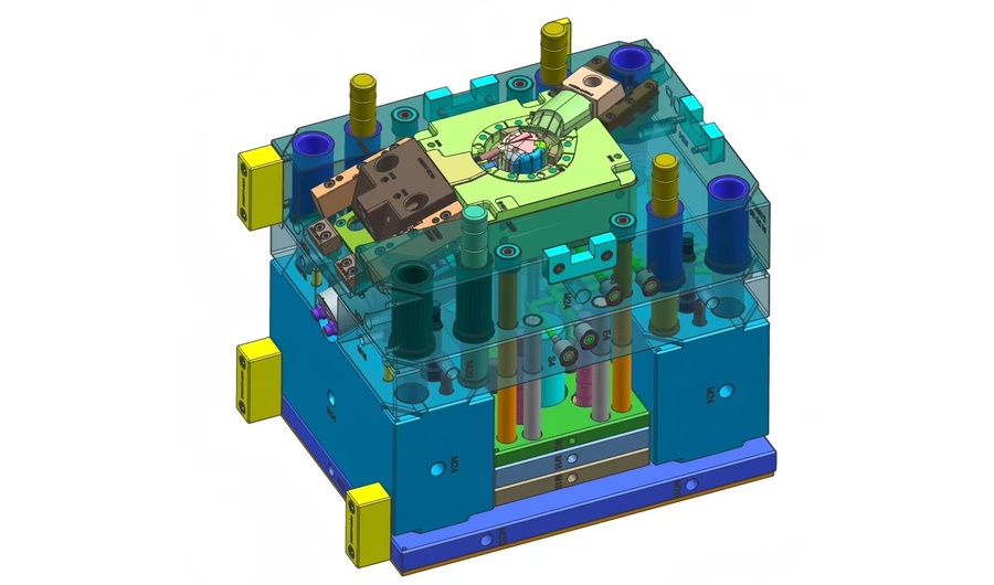
Short shot is one of the molding problems most factories will eventually run into, especially when producing thin-wall plastic parts or components with long flow distances. Sometimes the molding process looks completely normal, but the parts coming out of the mold are still not fully formed. You may see missing edges, incomplete features, or areas where the plastic never reaches the end of the cavity. This kind of defect usually means the molten material lost its ability to flow before filling the entire mold. As the plastic cools, it starts to freeze inside the cavity, blocking the remaining sections from being filled. The finished part often cannot pass quality inspection because of appearance defects, dimensional inaccuracy, or poor fit during assembly.
In some production runs, short shots appear only occasionally. In others, they become a repeating defect that generates continuous scrap and disrupts stable production. Either way, they affect molding stability, waste raw material, and reduce overall production efficiency.
What makes short shot troubleshooting difficult is that the problem is not always caused by a single factor. The root cause can be related to mold structure, gate design, venting, material flow behavior, machine performance, or processing conditions. The issue may come from poor venting, improper processing parameters, mold structure limitations, material flow behavior, or insufficient machine performance. The issue may come from poor venting, improper processing parameters, mold structure limitations, material flow behavior, or insufficient machine performance.
In this article, we’ll look at the most common causes of mold short shots and the practical troubleshooting methods molders use to solve them on the shop floor.
What Is a Mold Short Shot?
A mold short shot occurs when injected plastic does not completely fill the mold cavity during the injection process.
The unfilled area may appear as:
Missing corners
Incomplete ribs or bosses
Thin sections not filled
Rounded or unfinished edges
Flow hesitation marks
Partially formed geometry
In severe cases, entire sections of the product may be absent.
Short shots are especially common in:
Thin-wall injection molding
Large surface-area parts
Long flow length designs
Multi-cavity molds
Engineering resin applications
Parts with poor venting systems
The defect usually develops because the melt front loses pressure, temperature, or flow momentum before the cavity is completely packed.
The 7 Most Common Causes of Mold Short Shot
1. Insufficient Injection Pressure
This is one of the first things technicians check. If injection pressure is too low, the melt simply cannot overcome the resistance inside the runner system and cavity. The plastic slows down before reaching the end of fill.
Typical signs include:
Consistent underfilling
Missing features at the flow end
Short shots in thin-wall areas
Parts improving temporarily when pressure increases
Common reasons behind low effective pressure:
Injection pressure setting too low
Pressure loss through long runners
Restrictive gates
Small nozzle diameter
Excessive flow resistance
Solutions:
Increase injection pressure gradually
Optimize gate dimensions
Reduce unnecessary flow restrictions
Verify machine pressure capability
Check for partially blocked nozzles or runners
2. Melt Temperature Too Low
The flow behavior of molten plastic is heavily affected by temperature. When the melt temperature is not high enough, the material becomes thicker and harder to flow through the runner system and cavity. As the plastic moves forward, it can cool down too quickly and begin solidifying before the cavity is fully filled.
Engineering materials such as PC, nylon, and flame-retardant resins are usually more sensitive to processing temperature changes, making them more likely to experience filling problems if the melt temperature is unstable or set too low.
Common symptoms:
Matte flow appearance
Hesitation marks
Short shots in long-flow regions
Higher injection pressure requirement
Solutions:
Increase barrel temperature zones carefully
Verify actual melt temperature, not only machine settings
Improve screw recovery consistency
Reduce excessive cooling near gates
Avoid overly cold mold temperatures
3. Poor Mold Venting
Many short shot problems are actually air problems. When molten plastic enters the cavity, the trapped air must escape quickly. If venting is insufficient, compressed air creates resistance against the incoming melt front. In some cases, trapped gas pressure becomes strong enough to stop filling entirely.
Poor venting often causes:
Burn marks near end-of-fill
Random short shots
Inconsistent filling behavior
Gas traps
Gloss variation
Areas commonly lacking venting:
Deep ribs
Thin sections
End-of-fill regions
Slider shut-offs
Around inserts
Solutions:
Add or deepen vents properly
Improve parting line venting
Use vent pins where necessary
Clean blocked vent channels
Reduce trapped air pockets during mold design
Good venting is one of the most underestimated factors in injection molding stability.
Mold Short Shot Troubleshooting Flow
When diagnosing a short shot issue, experienced molders usually follow a logical sequence instead of changing random settings.
Step 1: Verify Material Supply
First confirm:
Hopper feeding correctly
No bridging inside hopper
Proper resin drying
Correct material loaded
No contamination
Sometimes the “short shot” is simply inconsistent material feeding.
Step 2: Check Fill Percentage
Run a short-shot study by gradually reducing fill until the flow pattern becomes visible. This helps identify:
Flow hesitation zones
Air traps
Pressure loss regions
Weld line formation
Gate balance issues
A controlled short-shot study often reveals more than trial-and-error adjustments.
Step 3: Analyze Gate and Runner Design
Undersized gates are a common hidden cause. If the gate freezes too early, the cavity loses packing pressure before complete filling occurs.
Review:
Gate size
Gate location
Runner diameter
Runner balance
Flow length-to-thickness ratio
Step 4: Evaluate Machine Capability
Sometimes the process is asking more than the machine can deliver.
Check:
Maximum injection pressure
Injection speed capability
Shot size utilization
Screw diameter suitability
Cushion stability
Machines operating near their maximum capacity often struggle with consistent fill performance.
Step 5: Inspect Mold Temperature Distribution
Uneven cooling can create localized freezing before the cavity fills completely.
Pay attention to:
Thin-wall areas
Long flow paths
Areas far from gates
Cooling line imbalance
Cold spots near inserts
Thermal imaging can sometimes expose hidden temperature imbalance inside the mold.
How Part Design Contributes to Short Shots
Not every short shot is a processing issue. Sometimes the product geometry itself creates impossible flow conditions.
Common design problems include:
Excessively thin walls
Long flow paths
Sudden thickness changes
Sharp corners
Poor gate placement
Materials Most Sensitive to Short Shot Problems
Higher-risk materials include:
Polycarbonate (PC)
Nylon (PA)
PPS
LCP
Flame-retardant compounds
Glass-filled materials
These materials often require:
Higher melt temperatures
Faster injection speeds
Better venting
Optimized gate design
Precise mold temperature control
Preventing Mold Short Shot Before Production
During mold design, engineers should evaluate:
Flow length-to-thickness ratio
Gate position
Venting strategy
Runner balance
Cooling efficiency
Material flow characteristics
Mold flow analysis can help predict filling issues early, especially for complex or thin-wall parts.
Practical Shop Floor Tips
Experienced technicians often use these methods:
Increase injection speed before increasing pressure
Raise mold temperature slightly for thin-wall parts
Monitor cushion consistency closely
Check vent cleanliness during maintenance
Avoid excessive regrind ratios
Confirm actual melt temperature using a melt probe
Reduce unnecessary flow restrictions inside runners
Conclusion
A mold short shot is rarely a random defect. It is usually a signal that something inside the molding system is restricting flow, losing pressure, trapping air, or freezing the material too early.
The real challenge is identifying where the restriction begins.
In some cases, increasing the injection speed is enough to solve the problem. But for more difficult situations, the fix may involve modifying the gate size, improving mold venting, changing part wall thickness, or checking whether the machine has enough injection capacity for the application.
Effective troubleshooting in injection molding is not about randomly changing settings. It comes from understanding how melt flow, cavity pressure, material temperature, and cooling behavior work together during the filling process. Once you understand that relationship, short shots become much easier to predict—and prevent.
- 6th May 2026
The Engine of the Cycle: A No-Nonsense Guide to Mold Cooling Design
Introduction
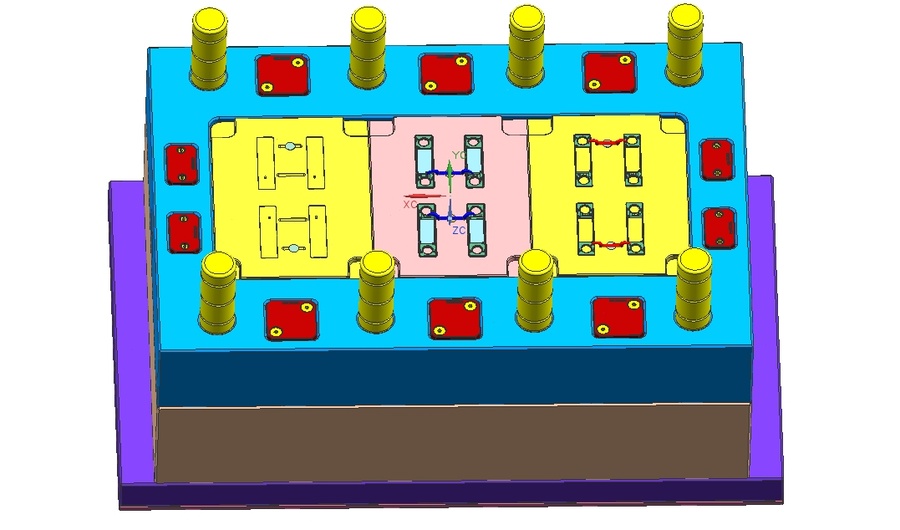
Let’s be real: cooling isn’t just a “phase” of the injection molding cycle; it is the cycle. It usually eats up 60% to 80% of your total time on the press.
If your cooling system is an afterthought, you’re essentially leaving money on the table every time the mold opens. A well-engineered system is the difference between a high-speed production run and a “scrap-making machine” that produces warped, inconsistent parts.
Why Cooling is the “Heartbeat” of the Tool
Molds need to breathe—plain and simple. You’re forcing 250°C liquid into a tool and expecting it to become a rock-solid part almost instantly.
But if that cooling isn’t perfectly balanced, you’re in for a headache. One side freezes, the other pulls, and suddenly your precision part is curling like a potato chip.
If you’re chasing dimensional stability, you can’t just ‘hope’ for even cooling; you have to engineer it into the foundation of the tool.
Every second you shave off that cooling cycle by optimizing your “hot spots” is a direct injection of profit into the life of the mold.
Layout Strategy: Don’t Just Drill Holes
The goal is simple but tricky: get the water as close to the cavity as you dare without compromising the structural integrity of the steel.
The “Golden Rule”
We generally try to keep the center of the cooling lines about 1.5 to 2 diameters away from the cavity surface.
Too far, and the heat lingers; too close, and you risk a catastrophic “blowout” under the pressure of the injection.
Contouring is King
For flat panels, a basic grid works fine. But for complex 3D shapes, your cooling lines need to mimic the part’s geometry.
If the part is complex, don’t be afraid to look at Conformal Cooling (3D printed inserts).
Look, the upfront cost for conformal cooling is steeper, but it’s the only real way to kill those ‘unsolvable’ hot spots that a traditional drill bit just can’t touch.
It’s about eliminating the bottleneck before it eats your profit.
The Speed of the Flow
Don’t just turn on the water and assume the tool is cooling.
It’s not just about flow; it’s about turbulence. You need to hit a Reynolds number over 4,000 to actually scrub the heat off the steel.
If that coolant is just ‘lazy-rivering’ through the lines, it’s not doing its job—you’re basically just circulating lukewarm water while your cycle time suffers.
Getting into the “Dead Zones”
Deep cores and tight pockets are a cooling nightmare because you can’t just drill a straight hole into them. You’ve got to get creative with your plumbing:
Bubblers
For those deep, skinny cores where a standard drill bit is useless, we rely on Bubblers.
You’re basically sticking a tube up a blind hole to spray water directly at the ‘hot spot’ at the very tip.
The coolant hits the top and tumbles back down around the outside of the tube.
It’s the only real way to stop those narrow features from turning into heat traps that bake your plastic and ruin the cycle.
Baffles
Then you’ve got Baffles. These are essentially metal dividers you drop into a cooling line to stop the water from taking the ‘easy way out.’
By forcing the coolant to snake and churn around a curved blade, you’re maximizing its contact with the hot steel.
It’s all about making sure the water actually spends enough time ‘scrubbing’ the heat off the mold before it heads for the exit.
A Hard Truth from the Floor
If you can’t pull these inserts out to clean them, you’re in trouble.
Over time, mineral scale and gunk will calcify inside these lines.
If you don’t design them for easy maintenance, you’ll watch your cycle times slowly creep up month after month as the ‘veins’ of your tool get clogged.
Don’t wait for a total blockage to realize you should have made them easier to scrub.
Optimization: Stop the Guesswork
Don’t wait until the mold is on the press to find out it’s running hot.
Simulate it first
Use mold flow analysis to hunt for “hot spots” before you ever cut a piece of steel.
It’s a lot cheaper to move a cooling line on a screen than it is to weld and re-drill a hardened cavity.
Watch the “Delta T”
In production, monitor the temperature difference between your inlet and outlet.
If you’re seeing a jump of more than 3°C to 5°C, your circuit is unbalanced.
One side of your mold is working too hard while the other is coasting.
Water Quality is a Tooling Issue
Scale buildup inside your lines is like high blood pressure for your mold.
Use treated water to prevent algae and mineral deposits.
If your lines get “clogged,” your heat transfer efficiency drops off a cliff.
The Bottom Line
Your cooling system is the “engine” that drives your cycle time.
Treat it like a secondary plumbing job, and you’ll pay for it in long cycles and warped parts.
Treat it like a precision-engineered thermal management system, and you’ll have a tool that runs fast, stays stable, and makes money.
Practical Takeaway
Invest in the cooling design during the CAD phase.
Shaving two seconds off a 20-second cycle might not sound like much, but over a million shots, that’s 550 hours of machine time you just handed back to your bottom line.
- 5th May 2026
Choosing the Right Mold Steel: A Practical Guide to Cost, Performance, and Tool Life
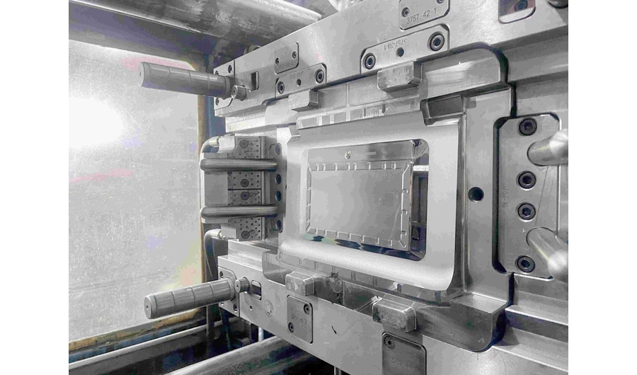
Choosing your mold steel isn’t just a technical box to check; it’s a high-stakes financial decision. The steel you pick dictates how long the tool lasts, how fast it cools, and—most importantly—how much you’re going to spend on maintenance down the road. You’re essentially balancing the “cost of the block” against the “cost of the millionth part.”
Here is how we look at steel selection on the shop floor.
1. P20: The Industry Workhorse
If you’re running a general-purpose project with a production volume under 500,000 shots, P20 is usually your best friend.
The beauty of P20 (1.2311 or 1.2312) is that it comes pre-hardened. You can machine it, sink your EDM, and it’s ready to go without a trip to the heat treater. This saves you weeks in lead time and keeps your upfront costs down. It’s tough enough for most consumer goods and electronics, but don’t expect it to hold a perfect mirror finish forever. It’s also prone to rusting if you’re in a humid environment or running “sweaty” cooling lines, so keep it oiled.
2. H13: The Heavy Hitter for High Volume
When you’re looking at millions of cycles—or you’re running abrasive resins at high speeds—you need to step up to H13.
Unlike P20, H13 is a “hot-work” steel. We machine it while it’s soft (annealed), then send it out for heat treatment to reach 44–52 HRC. This makes the cavity surfaces incredibly durable and resistant to “heat checking” (those tiny cracks that form after thousands of thermal cycles). Yes, it’s more expensive, and yes, the lead time is longer because of the hardening process, but it’s the only way to ensure the tool doesn’t fall apart before the project hits its ROI.
3. Stainless Steel: The Solution for “Nasty” Resins
If you’re molding PVC, flame-retardant materials, or anything that releases corrosive gases, 420 Stainless Steel (1.2083) is non-negotiable.
Regular tool steels will literally start to rot or “pit” when exposed to the acidic gasses released during the melt. Stainless steel is a nightmare to machine compared to P20, and it’ll cost you more upfront, but it’s the only way to avoid a scenario where your cavity finish is ruined after just a few weeks of production. It’s also the gold standard for medical and food-grade parts where cleanliness is everything.
4. Specialty Grades: S7 and Beryllium Copper
Sometimes, standard steel just doesn’t cut it.
S7 (The Tough Guy)
If your mold has thin, fragile shut-offs or is prone to “cold-start” impacts, S7 is your insurance policy. It’s incredibly shock-resistant—it’ll bend before it chips.
Beryllium Copper (The Heat Sink)
If you have a “hot spot” in your part that just won’t cool down, don’t use steel. We use Beryllium Copper inserts because they pull heat away three to five times faster than steel. It’s expensive and soft, but it can shave 5 or 10 seconds off a cycle time, which pays for itself in a month.
5. Aluminum: For the “I Need It Yesterday” Crowd
7075 Aluminum is great for prototypes or low-volume runs (under 10,000 shots). It’s lightning-fast to machine and pulls heat away beautifully. Just don’t expect it to hold tight tolerances for long, and definitely don’t try to run glass-filled nylon through it unless you want the cavity to look like it was hit with a sandblaster.
The Practical Takeaway: Match the Steel to the Life of the Part
The biggest mistake you can make is “over-speccing” a tool. You don’t need H13 for a 20,000-part test run, and you shouldn’t trust P20 for a 10-year automotive contract.
My Advice:
Know your volume: Be realistic about how many parts you’re actually going to make.
Look at your resin: If it’s abrasive or corrosive, let the material dictate the steel.
Talk to your mold maker early: We know which steels “behave” during machining and which ones are prone to cracking during heat treat.
At the end of the day, the incremental cost of better steel is a drop in the bucket compared to the cost of a tool that fails in the middle of a production rush.
- 4th May 2026
Injection Mold Troubleshooting: Solving 12 Common Problems
Introduction
Look, we’ve all stood by the press watching a bin fill with scrap and felt that exact same frustration. Whether you’re fighting a short shot that won’t fill or a burn mark that just won’t quit, troubleshooting is where the real work happens.
You can’t just cross your fingers and hope the machine fixes itself; you have to figure out exactly why the physics of the mold are fighting you today.
But here is the secret—most defects aren’t “mysteries.” They are the result of physics being ignored.
To save your uptime, you need to stop guessing and start diagnosing.
Here is how to tackle the most common headaches on the production floor.
1. The Frustration of Short Shots
A short shot is exactly what it sounds like: a cavity that just won’t fill. If you’re looking at a partial part, you’re essentially losing the race against the “freeze.”
What’s happening?
When you’re staring at an incomplete part, you’re basically losing a race against the material’s freeze point.
Most of the time, the melt is behaving like cold molasses, or your injection pressure is hitting a wall of resistance—it just can’t climb.
But don’t overlook the air—if it’s trapped in a dead-end pocket with no way out, there’s simply no room for the plastic to enter, period.
The Fix
Before you start blindly cranking up the pressure, take a hard look at your heats.
If the resin is fluid enough, go hunt for gunked-up or blocked vents.
If you’re still coming up short after that, you’re likely looking at a design flaw—that gate might just be way too tight for the resin you’re trying to push through it.
2. Dark Scorch Marks (The Diesel Effect)
Those ugly black streaks at the end of the fill path are almost always “burn marks.”
In the shop, we call this the diesel effect because you’re essentially creating a miniature combustion engine inside the tool.
The Culprit
Air is getting trapped, compressed, and heated to the point where it literally chars the plastic.
This usually happens because the injection speed is too aggressive or the venting is nonexistent.
The Fix
Slow down the injection speed during the final stage of the fill to let the air escape.
If that doesn’t work, you need more vents (or deeper ones) exactly where that burn is appearing.
3. Sink Marks: The Nemesis of Thick Parts
Sink marks are those irritating dips that always seem to haunt the thickest areas of your part, like ribs or bosses.
It really boils down to a lack of “feed.”
If you don’t shove enough extra plastic into the cavity during the packing stage, the molten core will actually tug the surface inward as it cools and shrinks.
You’re essentially watching the part cave in on itself because it didn’t have enough material to fill the volumetric void left by the cooling process.
The Fix
You need more “pack and hold.”
Increase your holding pressure or extend the hold time.
Also, take a look at your cooling—if the core is staying too hot, the sink will never go away.
Long term? Redesign the part with more uniform wall thicknesses.
4. Warpage: The “Potato Chip” Effect
There is nothing worse than a part that looks perfect in the mold but curls like a potato chip once it hits the bin.
The Root Cause
This is almost always a result of “differential shrinkage.”
If one side of the part cools faster than the other, the internal stresses will pull it out of shape.
It can also happen if your packing pressure is so high that you’re locking stress into the molecular structure.
The Fix
Balance your cooling.
Check the inlet/outlet temps on both halves of the mold.
You want the part to cool as uniformly as possible.
If the part is still twisting, try backing off the pack pressure or adjusting the mold temperature to relieve that internal tension.
5. Flash: Plastic Looking for an Exit
Flash is that paper-thin “wing” of plastic leaking out at the parting line.
Flash is more than just a messy waste of resin—it’s a tool-killer.
When you see plastic blowing past the parting line, you’re usually looking at a power struggle between injection pressure and clamping force.
Most of the time, either the press doesn’t have the muscle to keep the halves shut, or your shut-off surfaces have finally been beaten out of alignment after a few thousand too many cycles.
Whatever the cause, it’s a red flag that you’re either overpowering the machine or your tool needs a serious regrind.
The Fix
First, dial back the injection pressure and velocity.
If the mold is still “opening” under pressure, check your clamp settings.
If the tool itself is worn, it’s time to pull it for a regrind of the shut-off surfaces.
Conclusion
Injection mold troubleshooting isn’t about luck.
Most molding defects are simply the visible result of heat, pressure, flow, and cooling falling out of balance.
Once you understand the physics behind the defect, the solution usually becomes obvious.
Stop guessing. Start diagnosing.
Our Service

Project Engineering & DFM
We don't just receive your file and start cutting. Before any steel is touched, our engineers review your design to catch the problems that cost you money later. One engineer owns your project from your first message to final shipment.
Learn More
Precision Mold Machining
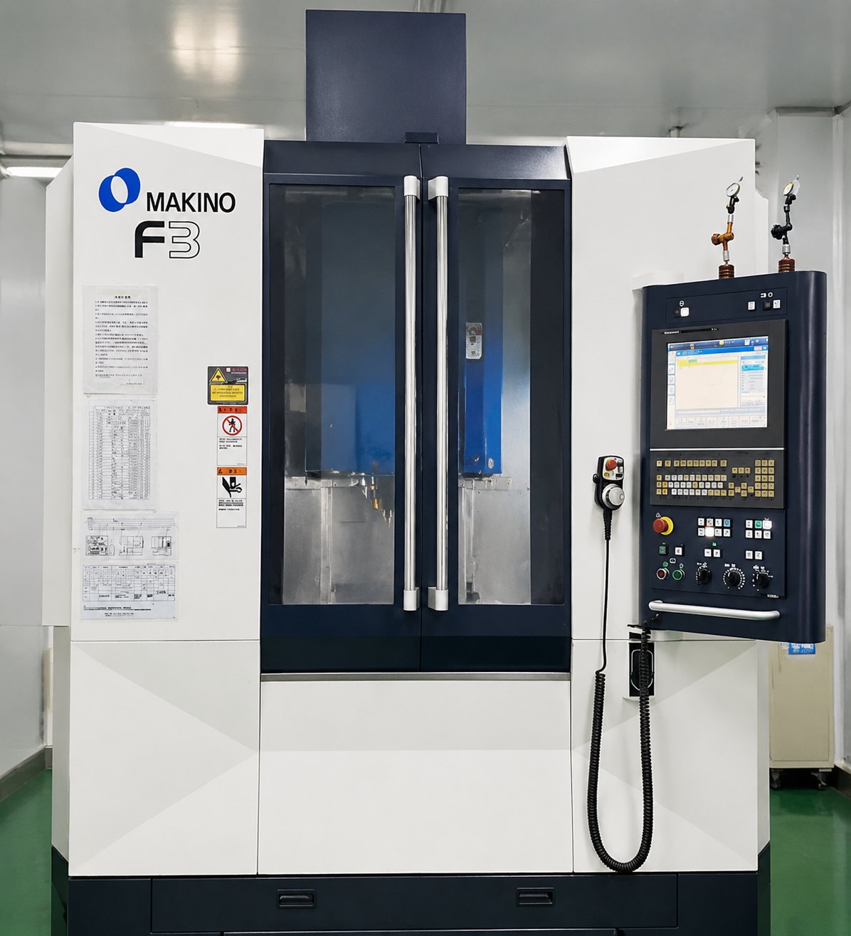
→CNC Machining (±0.005mm)
→EDM — complex cavities others can't cut
→Wire EDM — intricate profiles, zero distortion
Learn More

Mold Trial & Production
→Trial Mold & First-Shot Review
→Low-Volume Production (100–50,000 pcs)
→Full Dimensional Inspection & QC Report
Learn More

Global Delivery & Logistics Support
From mold completion to finished plastic parts arriving at your warehouse,
we coordinate manufacturing, packaging, customs and transportation under one project management system
Learn More



Contact Us