
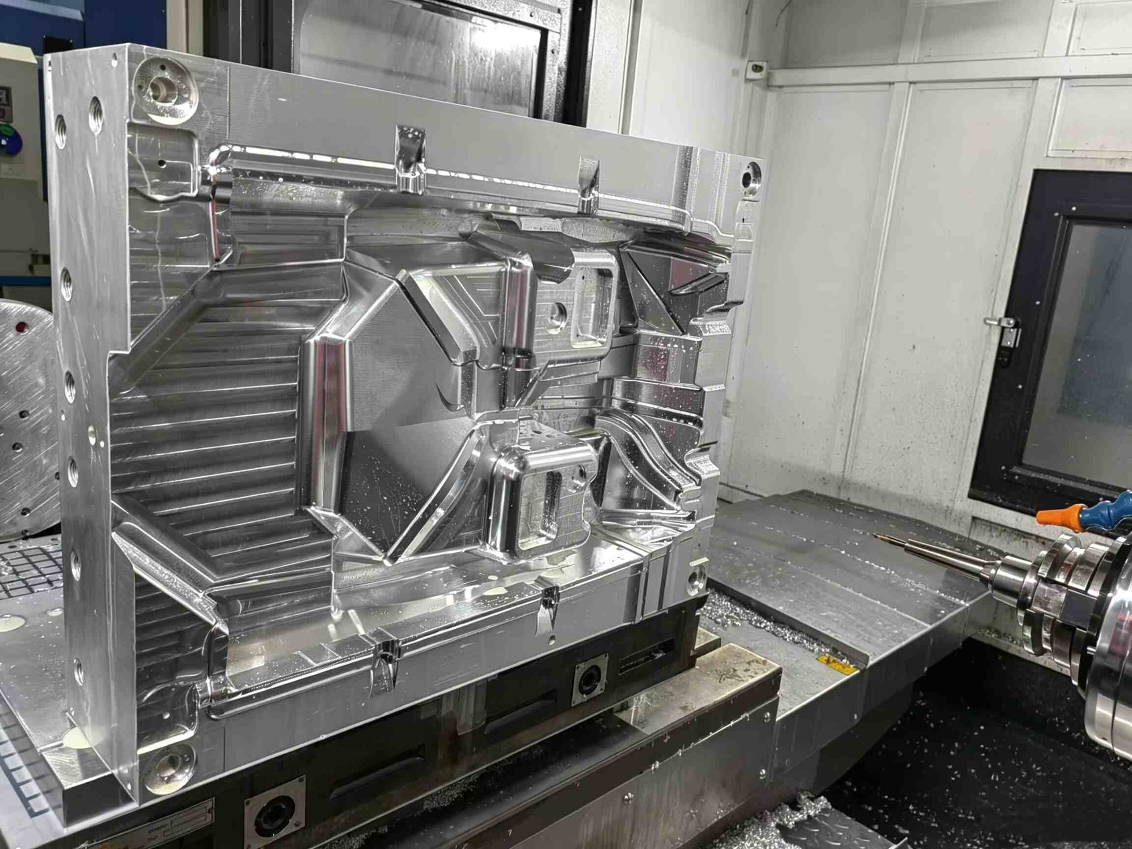
¿Por qué las socavaduras internas son un problema grave en el moldeo por inyección?
-
 Aronna Zheng
- 15 de abril de 2026
Seamos sinceros: los rebajes internos son una pesadilla para los diseñadores de moldes. A diferencia de las características externas, no se pueden solucionar con deslizadores estándar.
Si la geometría no está diseñada correctamente, las consecuencias son graves:
- Piezas adheridas permanentemente al núcleo
- Daños superficiales o rozaduras
- rotura de la varilla del elevador
- Costosos tiempos de inactividad de la producción
Cuando se trata de clips o soportes internos, el levantador de moldes se convierte en la solución mecánica más fiable.
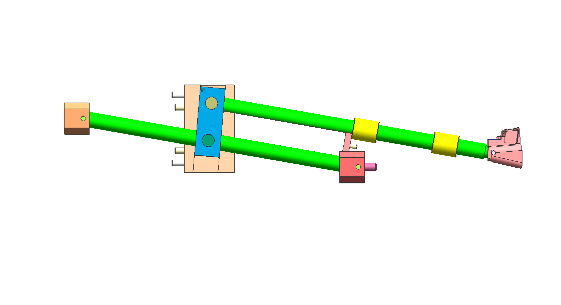
Cómo funciona un elevador de moldes: El principio del "paso lateral"
Un elevador de moldes no se mueve como un deslizador tradicional. En cambio, es impulsado por el sistema de expulsión.
Durante el ciclo de eyección:
- El elevador se mueve hacia arriba con la placa eyectora
- Al mismo tiempo, sigue una camino en ángulo
- Esto crea una combinación movimiento vertical + lateral
Este movimiento lateral, a menudo llamado "esquivar"—es lo que libera el corte inferior.
Regla de diseño clave
Permitir siempre al menos 2 mm de recorrido adicional más allá de la profundidad de socavación.
Cualquier cantidad inferior aumenta el riesgo de:
- marcas de arrastre
- Arañazos superficiales
- Lanzamiento incompleto
El error más común: Ángulo incorrecto del elevador
Uno de los mayores errores de diseño es inclinar demasiado el ángulo de elevación para ahorrar espacio.
Ángulo de elevación recomendado
- Rango óptimo: 5° – 11°
Zona de riesgo
- Por encima de 15°: Alto riesgo de unión y fallo
En ángulos más pronunciados:
- La fuerza lateral aumenta significativamente
- El movimiento vertical se ve restringido.
- El elevador puede atascarse o la varilla puede doblarse.
Cuando los ángulos pronunciados son inevitables
Si su diseño requiere un ángulo mayor, considere lo siguiente:
- Base elevadora con bisagra
- Diseño de elevador con ranura en T
Esto ayuda a reducir la tensión en la varilla del elevador y mejora su durabilidad.
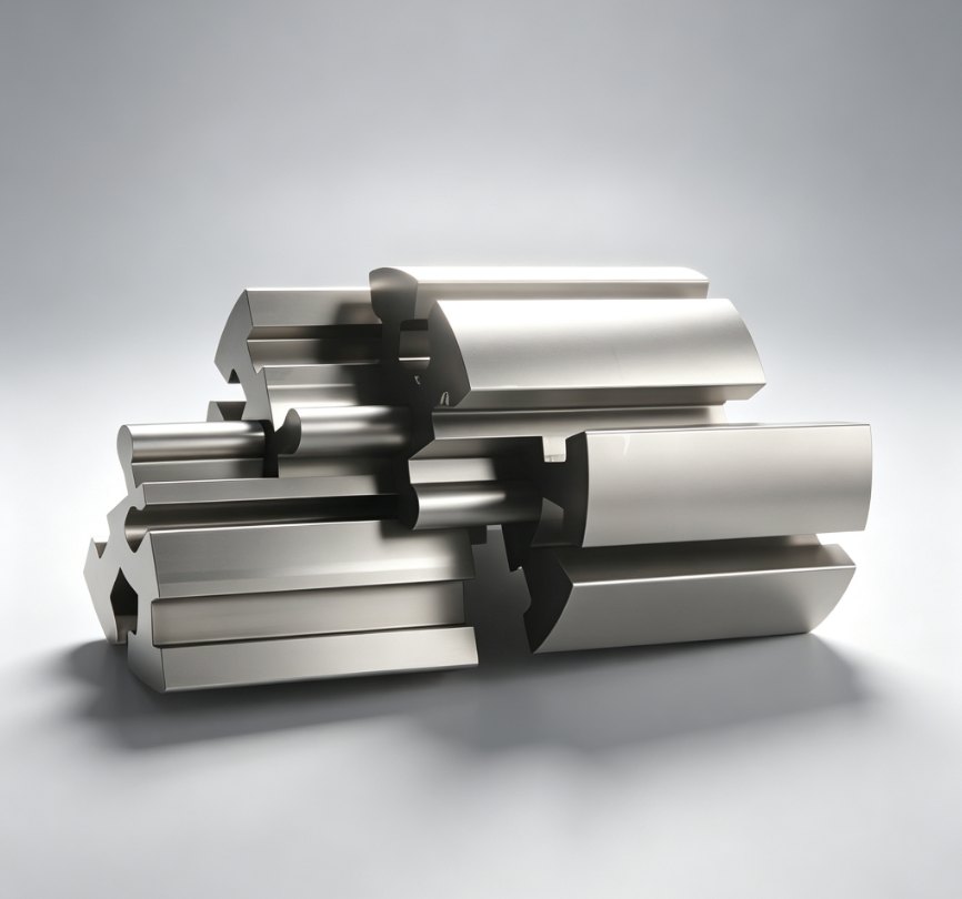
Selección de materiales: Previene el desgaste y el roce.
Los sistemas de elevación funcionan bajo las siguientes condiciones:
- Presión alta
- Temperatura alta
- Contacto continuo metal-metal
Elegir el material incorrecto puede conducir a mortificantedonde las superficies se sueldan entre sí y fallan.
Materiales recomendados
- acero para herramientas H13
- Acero pretemplado 718H
Guía de dureza
- Objetivo: 50–54 HRC
- Mantén el elevador ligeramente más duro que el núcleo.
Opción de alto rendimiento
Para tiempos de ciclo más rápidos:
- Usar Insertos de cobre-berilio
Beneficios:
- Disipación de calor más rápida
- Tiempo de enfriamiento reducido
- Mayor eficiencia de producción
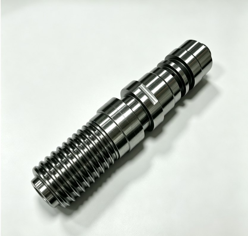
3 consejos de expertos para un diseño de elevador a prueba de balas
1. Añadir una guía de “cola”
Sujete siempre la parte inferior de la varilla elevadora con un bloque guía.
Sin apoyo:
- La varilla vibra
- La vibración provoca destellos y desgaste.
2. Utilice ranuras de aceite
La fricción es el enemigo de cualquier componente móvil.
Buenas prácticas:
- Añada ranuras de lubricación a las superficies deslizantes.
Excepción:
- Moldes médicos → utilice recubrimiento DLC en lugar de aceite
3. Controlar el ajuste de la línea de separación (PL)
La superficie de cierre del elevador debe coincidir perfectamente con el núcleo.
Incluso un espacio de 0,01 mm puede causar:
- Líneas de testigos visibles
- Mala calidad de la superficie
Elevador vs. Deslizador: ¿Cuál debería usar?
La elección entre un elevador y un deslizador depende completamente de la ubicación del rebaje.
Utilice un control deslizante cuando:
- El rebaje es externo.
- Hay suficiente espacio para la acción paralela.
Utilice un elevador cuando:
- El socavado es interno.
- El espacio es limitado
- Los sistemas hidráulicos no son prácticos
Reflexiones finales
Un elevador de moldes es una de las soluciones más eficientes para socavados internos, pero solo si está diseñado correctamente.
Al controlar:
- Ángulo
- Autorización de viaje
- Selección de materiales
- Soporte estructural
Puedes convertir una característica de alto riesgo en una Mecanismo fiable y repetible que mantiene su línea de producción funcionando sin problemas.
¿Necesita ayuda para optimizar el diseño de su molde o para resolver socavados complejos?
Visita www.xinkeymould.com Para obtener asistencia experta y mejorar el rendimiento de sus herramientas.


Contacta con nosotros