-
Inicio

-
Capacidad
- Moldes de inyección de plástico
- Molde de inyección de dos componentes para piezas de dos materiales (molde 2K)

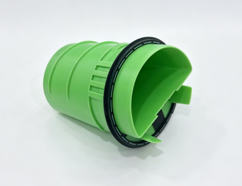
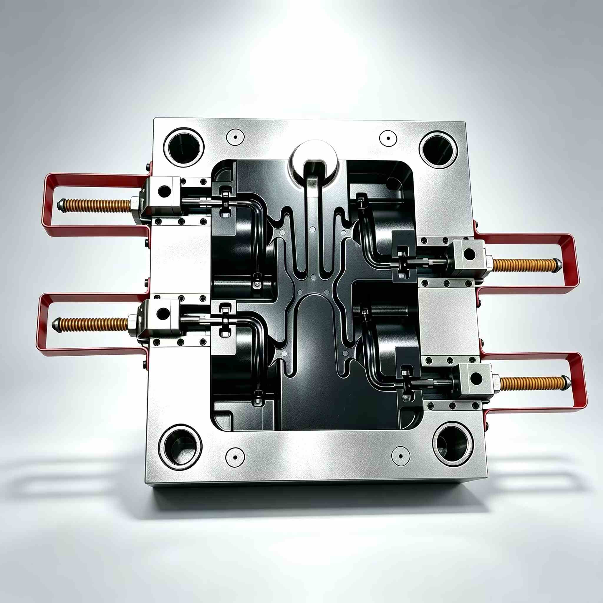
Molde de inyección de dos componentes para piezas de dos materiales (molde 2K)
Dos materiales. Un ciclo de moldeo. Una pieza terminada.
Diseñado para productos que requieren superficies suaves al tacto, sellos integrados o apariencia bicolor, sin el trabajo de ensamblaje adicional.
Diseñado para productos que requieren superficies suaves al tacto, sellos integrados o apariencia bicolor, sin el trabajo de ensamblaje adicional.
- Reemplazar el pegado y el ajuste manual
- Reduzca el riesgo de defectos de montaje
- Soporte para DFM, Moldflow, utillaje y muestreo.
- Solucione los problemas de unión con el moldeo por inyección 2K profesional.
1. Descripción general del producto
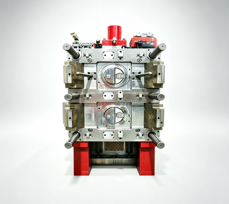
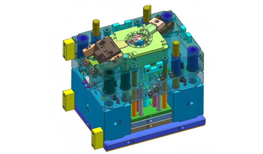
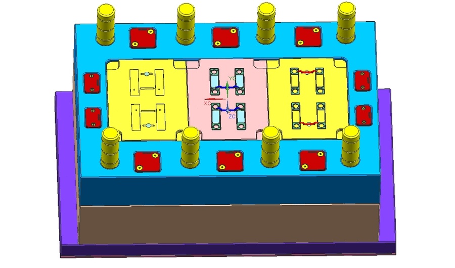
A two-shot injection mold—also called a 2K mold or multi-component mold—produces plastic parts composed of two different materials or colors in a single molding cycle on a dedicated two-shot injection machine with dual injection units. In the typical rotary platen configuration, the first material injects into cavity set A, then the rotary platen indexes 180 degrees, moving the shot-1 part into cavity set B where the second material injects directly onto or around it. The engineering challenge lies in three areas: indexing precision so the shot-1 part seats perfectly in cavity B every time, shut-off surfaces that withstand second-shot injection pressure without flashing, and material pair selection that ensures reliable bonding. At XINKEY MOULD, we design 2K molds around your specific material combination—whether PP+TPE for power tool grips, PC+ABS for enclosures, PMMA+PC for automotive lenses, or PA+TPU for medical seals.
2. ¿Qué problemas puede solucionar este producto?
Flash en la interfaz de segundo disparo
The most common defect in 2K molding: second material bleeds past the shut-off surface and covers cosmetic areas of the first material. This happens when shut-off steel does not perfectly match the shot-1 part profile—due to thermal expansion mismatch or shrinkage. XINKEY MOULD designs shut-off surfaces with 0.02-0.03mm interference fit at operating temperature, factors in thermal expansion coefficients of both materials, and uses mold flow to verify that injection pressure does not open the shut-off during fill.
Mala adherencia entre materiales incompatibles
Not every pair of thermoplastics bonds well. PP and TPE bond through mechanical interlocking if the interface is properly designed, but PP and PA will delaminate without a tie layer. XINKEY MOULD’s DFM review includes a material compatibility assessment based on your target material pair, and we advise on chemical bonding, mechanical interlock, or tie-layer strategy before tooling starts.
Desalineación de indexación después del ciclo térmico
Un molde de platina giratoria funciona a altas temperaturas durante horas. El acero se dilata, el mecanismo de indexación se desgasta y lo que estaba perfectamente alineado al inicio puede desviarse 0,05 mm después de 8 horas de producción continua, lo que provoca un espesor de pared irregular en la segunda inyección o una diferencia visible entre colores. Nuestros moldes 2K utilizan enclavamientos de posicionamiento endurecidos entre las mitades giratoria y estacionaria, con pasadores guía resistentes al desgaste que mantienen la alineación de indexación dentro de 0,02 mm durante la vida útil nominal del molde.
3. Aplicaciones típicas
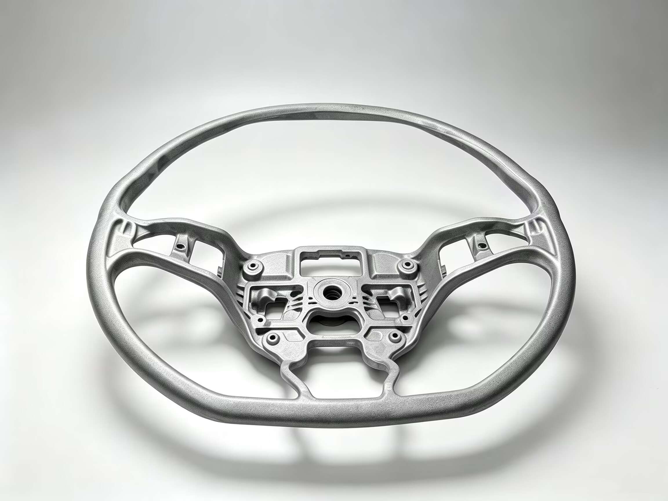
Empuñaduras y mangos de herramientas eléctricas de tacto suave
Núcleo estructural rígido de PP o PA sobremoldeado con TPE o TPU para un agarre ergonómico y amortiguación de vibraciones. Generalmente, configuraciones de 2+2 o 4+4 cavidades. La clave reside en lograr una transición limpia y sin huecos entre los materiales duros y blandos en la línea de separación, visible para el usuario final en cada superficie de agarre.
Lentes y carcasas para faros de automóviles
Luces automotrices bicolores (intermitente ámbar en una toma, sección roja o transparente en la segunda) fabricadas como una sola pieza. El requisito óptico añade complejidad: la interfaz de los dos materiales debe estar libre de burbujas, distorsiones y tensiones internas que afecten la transmisión de la luz o generen deslumbramiento. Pares comunes: PMMA y PC.
Sellos para dispositivos médicos y componentes para el recorrido de fluidos
Cuerpo rígido de PP o COC con junta de TPE integrada moldeada en la segunda inyección, lo que crea un conducto de fluido hermético sin necesidad de un conjunto de juntas independiente. Es común en dispositivos médicos desechables, componentes de inhaladores y consumibles de diagnóstico, donde la eliminación de un paso de ensamblaje manual mejora tanto el costo como el control de la contaminación.
Botones y teclados de electrónica de consumo
Teclas rígidas de PC o ABS con botones de TPE blandos moldeados a través de la tecla en la segunda inyección, lo que proporciona respuesta táctil y protección contra el polvo y el agua. El material de la segunda inyección debe rellenar con precisión las pequeñas aberturas de la primera inyección sin que sobresalga de la superficie visible.
4. Tabla de especificaciones
| Artículo | Detalles |
| Tipo de molde | Molde de inyección de dos componentes / Molde 2K / Molde multicomponente |
| Configuración | Platina giratoria (índice de 180°), transferencia con núcleo o transferencia robótica |
| Ejemplos de pares de materiales | PP + TPE, PA + TPU, PC + ABS, PMMA + PC, PBT + LSR |
| Mecanismo de enlace | Unión química, enclavamiento mecánico o capa de unión (por par de materiales) |
| Precisión de la indexación | ≤0,02 mm mantenido durante la vida útil nominal del molde |
| Rango de cavidades | Normalmente de 1+1 a 4+4; las configuraciones más grandes se evalúan según el proyecto. |
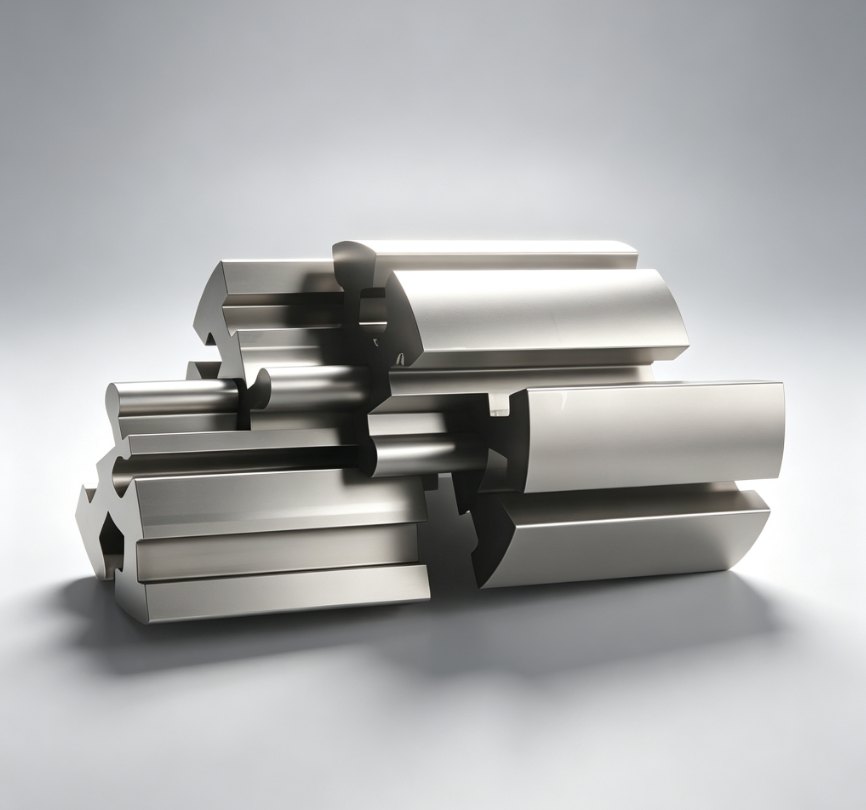
| Acero para moldes | H13 / S136 para alto volumen; insertos D2 en superficies de cierre; P20 para prototipos |
| Enfriamiento | Circuitos independientes para la cavidad A y la cavidad B (con diferentes temperaturas de material). |
| Ventaja del tiempo de ciclo | Reducción del 30-50% en comparación con dos procesos de moldeo separados más el ensamblaje. |
| Soporte de diseño | DFM, análisis de compatibilidad de materiales, flujo del molde para ambas inyecciones, FEM de superficie de cierre |
| Apoyo para ensayos clínicos | Muestreo T1 para ambos disparos, prueba de resistencia de la unión, análisis de la interfaz de la sección transversal |
5. Proceso del proyecto y control de calidad
Fase 1: Análisis de pares de materiales
Acción:Analizar la combinación de materiales propuesta: compatibilidad química, solapamiento de temperaturas de fusión, diferencial de contracción y mecanismo de unión. Recomendar ajustes en la combinación de materiales si fuera necesario.
Enfoque de control de calidad:Nota sobre la compatibilidad de materiales: recomendación del método de prueba de adhesión, ventana de procesamiento (rangos de temperatura para ambos materiales), valores de compensación de contracción para cada conjunto de cavidades.
Fase 2: Diseño del molde e ingeniería de cierre
Acción:Diseño de molde 3D con superficies de cierre modeladas con una interferencia de 0,02-0,03 mm. Análisis de elementos finitos (FEA) del cierre bajo la presión de inyección de la segunda inyección. Diseño de mecanismo de indexación rotativo o de retroceso del núcleo.
Enfoque de control de calidad:Informe de verificación de interferencias de apagado. Simulación cinemática del movimiento de indexación. Revisión independiente del diseño del circuito de refrigeración.
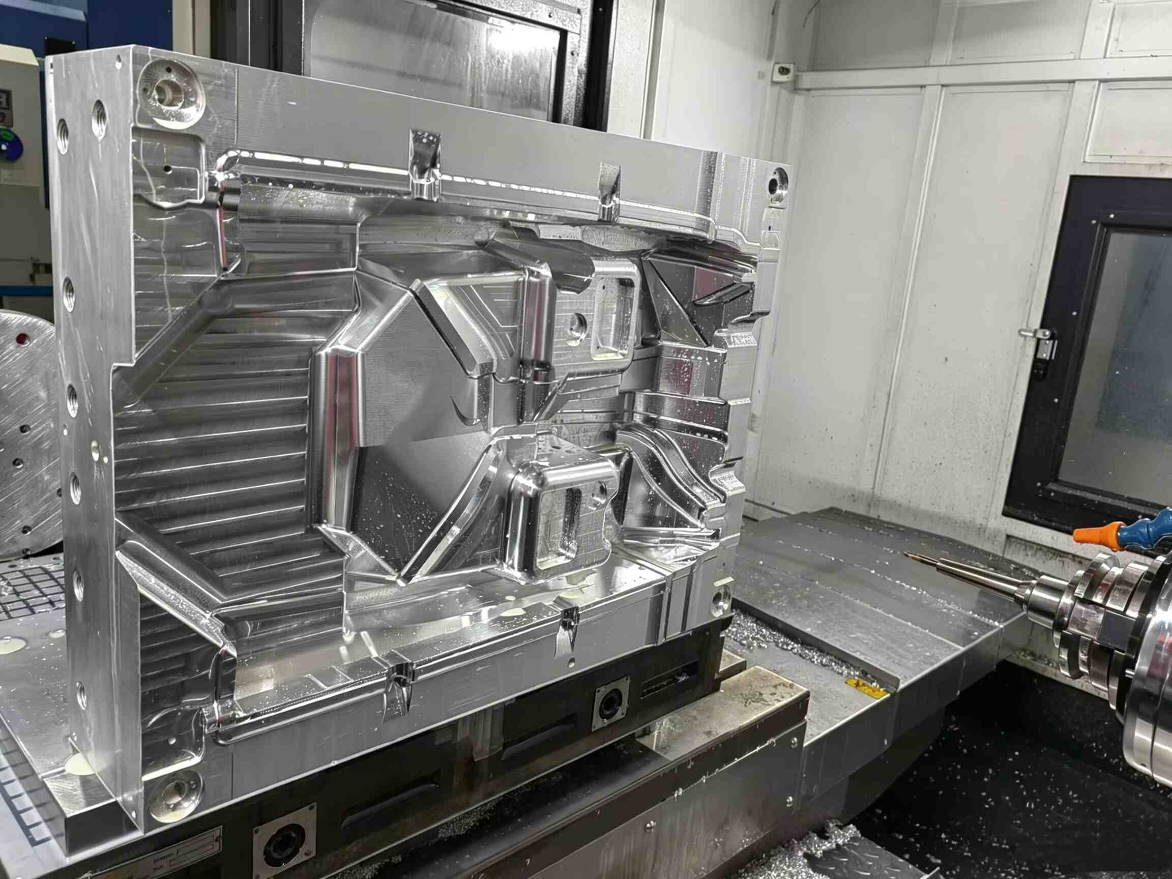
Fase 3: Mecanizado de precisión
Acción:Superficies de cierre rectificadas con precisión según las especificaciones de interferencia. Cavidades A y B mecanizadas con alineación de referencia de 0,01 mm. Endurecimiento de las superficies de desgaste.
Enfoque de control de calidad:Verificación de perfiles de cierre mediante CMM. Comprobación de la alineación del enclavamiento de localización. Medición de la rugosidad superficial en zonas de cavidades cosméticas.
Fase 4: Verificación del ensamblaje e indexación
Acción:Ensamblaje completo con mecanismo giratorio o de núcleo instalado. Prueba de indexación manual: 100 ciclos con medición de repetibilidad de alineación mediante comparador de cuadrante.
Enfoque de control de calidad:Informe de repetibilidad de indexación: desviación de alineación registrada cada 10 ciclos. Verificación de acoplamiento de enclavamiento. Prueba de presión del circuito de agua 8 bar/30 min.
Fase 5: Prueba T1 (ambas dosis)
Acción:Moldeado en máquina de moldeo por inyección de 2 componentes. Se optimizaron los parámetros de la inyección 1 y, posteriormente, los de la inyección 2 para lograr un llenado completo y una unión intacta. Se tomaron muestras de las piezas tras la estabilización del proceso.
Enfoque de control de calidad:Verificación del llenado de la segunda inyección (sin inyecciones incompletas ni rebabas al apagar el equipo). Prueba de resistencia de la unión en las piezas de muestra (despegue o cizallamiento según el método acordado). Informe dimensional de ambos materiales. Sección transversal para verificar la calidad de la interfaz.
Fase 6: Auditoría final y entrega
Acción:Limpieza final, protección contra la corrosión, embalaje con informe de verificación de alineación, hoja de parámetros de proceso para ambas unidades de inyección y juego de insertos de cierre de repuesto.
Enfoque de control de calidad:Paquete completo de documentación. Vídeo de prueba del molde. Guía de configuración del proceso para la máquina del comprador. Programa de mantenimiento para el mecanismo de indexación y la sustitución del inserto de cierre.
6. Why Choose XINKEY MOULD
Experiencia en la combinación de materiales
Hemos fabricado moldes 2K para empuñaduras de PP+TPE, carcasas de PC+ABS, lentes de PMMA+PC y juntas de PA+TPU. Esto significa que hemos acumulado datos de producción reales sobre lo que funciona para las combinaciones de materiales más comunes. No estimamos la resistencia de la unión; diseñamos la geometría de la interfaz y el rango de proceso basándonos en nuestra experiencia comprobada.
Diseño de cierre que resiste bajo presión.
El cierre entre la primera y la segunda inyección es donde fallan la mayoría de los moldes de dos componentes. Nuestro sistema de cierre utiliza simulación por elementos finitos (FEM) para verificar que la superficie de acero no se abra bajo la presión de la segunda inyección. Especificamos acero D2 endurecido o similar en las zonas de cierre y diseñamos insertos de cierre extraíbles para garantizar una larga vida útil.
Diseño de indexación listo para producción
Un molde de dos componentes que se indexa con precisión al configurarlo, pero que se desajusta después de 1000 ciclos, no es apto para la producción. Utilizamos componentes de guía endurecidos, enclavamientos cónicos y bujes resistentes al desgaste en todas las superficies de alineación móviles. Cada molde se entrega con un informe de verificación de repetibilidad de indexación que documenta la precisión de la alineación durante más de 100 ciclos manuales.
Diseño para la fabricación completo antes de comenzar con el utillaje.
Nuestro análisis DFM abarca la compatibilidad de los pares de materiales, la ubicación de la compuerta para ambas inyecciones, los requisitos de enfriamiento para cada material, la estrategia de cierre y el rango de tiempo del proceso en el que ambos materiales pueden moldearse juntos. Esta ingeniería inicial evita descubrir problemas de diseño fundamentales en la etapa T1, cuando el acero ya está cortado.
7. Preguntas frecuentes
P1: ¿Cuál es la diferencia entre el moldeo de dos componentes y el sobremoldeo por inserción?
El moldeo de dos componentes produce la pieza completa en un solo ciclo de máquina: ambos materiales se inyectan secuencialmente dentro del mismo molde en una máquina 2K. El sobremoldeo por inserción consiste en moldear un segundo material sobre una pieza prefabricada que debe cargarse en el molde de forma manual o robótica. El moldeo de dos componentes ofrece tiempos de ciclo más rápidos y un mejor control del proceso; el sobremoldeo por inserción es más flexible para volúmenes bajos o sustratos no moldeados por inyección.
P2: ¿Se adhieren químicamente todos los termoplásticos en un molde de dos componentes?
No. Algunos pares se unen químicamente: las formulaciones de TPE se unen con PP, y el PC con ABS debido a sus estructuras químicas similares. Otros pares, como el PP y el PA, no se unen químicamente y requieren una geometría de enclavamiento mecánico integrada en la primera inyección de la pieza. Evaluamos su par de materiales durante el DFM y le asesoramos sobre la estrategia de unión adecuada.
P3: ¿Qué configuración de máquina se requiere para el moldeo de dos componentes?
Una máquina de moldeo por inyección de dos componentes (2K) con dos unidades de inyección independientes y platina giratoria o capacidad de núcleo trasero. Si no dispone de una máquina 2K, podemos analizar si el sobremoldeo con insertos en una máquina estándar es una alternativa viable, o si el volumen del proyecto justifica la inversión en una máquina 2K.
P4: ¿Puede un molde de 2K producir piezas con más de dos materiales?
Existen moldes de tres y cuatro inyecciones (3K), pero requieren máquinas multiestación especializadas y son considerablemente más complejos. Para la mayoría de las aplicaciones, un proceso de dos inyecciones bien diseñado cubre las necesidades. Si su pieza requiere realmente tres materiales distintos, podemos evaluar su viabilidad en función de su equipo de producción y volumen objetivo.
P5: ¿Qué factores afectan al coste de un molde 2K?
Factores clave que influyen en el coste: complejidad de la superficie de cierre, número de cavidades (los moldes de dos componentes suelen tener menos cavidades que los moldes de un solo material, ya que cada conjunto de cavidades requiere refrigeración y alineación independientes), dificultad de la combinación de materiales y tipo de mecanismo de indexación. El sistema de platina giratoria es el más común; los sistemas de transferencia por robot y de núcleo posterior presentan perfiles de coste diferentes.
Productos
Fresado y torneado CNC
Fresado y torneado CNC de 5 ejes: mecanizado de precisión de 5 ejes para componentes metálicos y plásticos, desde prototipos hasta producción. El fresado multifacético en una sola configuración, combinado con el torneado CNC en una misma plataforma, elimina la necesidad de transferir piezas entre máquinas, ofreciendo una precisión de posición real de ±0,01 mm con tolerancia cero entre configuraciones. Servicio completo de mecanizado CNC para aluminio, acero, acero inoxidable, latón, POM, PEEK y plásticos de ingeniería.
Más información
Corte de alambre
Electroerosión por hilo: mecanizado de precisión mediante descarga eléctrica por hilo para perfiles 2D complejos, componentes de matrices con tolerancias ajustadas y piezas de acero endurecido que no se pueden fresar. Alcanza una precisión de ±0,003 mm y un acabado superficial Ra de 0,2 µm en acero para herramientas, carburo y metales duros conductores. Servicio esencial para insertos de moldes de inyección, componentes de matrices de estampado y herramientas de medición de precisión.
Más información
Mecanizado CNC de 5 ejes
5-Axis CNC Machining — Simultaneous 5-axis contouring for complex 3D surfaces, undercut geometries, and multi-sided parts in a single setup. Eliminates multiple fixturing operations and cumulative tolerance error. Ideal for impellers, turbine blades, orthopedic implants, and injection mold 3D cavity surfaces.
Más información
Erosión de chispas EDM
Electroerosión por descarga eléctrica (EDM): mecanizado de precisión de cavidades mediante electroerosión por penetración para esquinas internas afiladas, nervaduras profundas y geometrías 3D complejas en acero para herramientas endurecido. Utiliza electrodos de grafito o cobre mecanizados a medida para erosionar características inaccesibles para las herramientas de corte rotativas. Proceso fundamental para cavidades de moldes de inyección, utillaje de fundición a presión y cavidades ciegas que requieren una precisión de ±0,005 mm.
Más información
Molde de fundición a presión de zinc y piezas
Molde de fundición a presión de zinc: herramienta de precisión de cámara caliente para componentes de aleación de zinc de alta velocidad. Diseñado para la producción de piezas de pared delgada y forma final para molduras de automóviles, carcasas electrónicas y hardware de consumo, con tiempos de ciclo de tan solo 3 a 5 segundos y una calidad superficial uniforme tras la fundición.
Más información
Piezas de moldes de fundición a presión de magnesio
Molde de fundición a presión de magnesio: herramienta de alta presión con cámara fría diseñada para aleaciones de magnesio AZ91D, AM60B y AS41B. Diseñado específicamente para la reducción de peso en la industria automotriz, carcasas aeroespaciales y electrónica portátil, donde cada gramo cuenta. Produce componentes con forma final con un peso de 1,8 g/cm³, un 33 % más ligeros que el aluminio y un 75 % más ligeros que el acero.
Más información
Últimas noticias

- 29 de mayo de 2026
¿Por qué los equipos de desarrollo de productos suelen tener problemas con el moho y cómo prevenir retrasos costosos?
En muchos proyectos de desarrollo de productos, la mayor parte de la atención se centra en el producto en sí: su apariencia, funcionalidad, electrónica y experiencia de usuario.
Esta etapa suele avanzar rápidamente.
Los problemas reales a menudo surgen más tarde, cuando el diseño entra en la fase de utillaje y producción.
La razón es simple:
La mayoría de los ingenieros de producto no son ingenieros de moldes.
Pueden comprender muy bien el producto en sí, pero carecen de experiencia en el diseño de estructuras de moldes de inyección, la viabilidad del utillaje y la optimización de piezas de plástico orientadas a la producción. Como resultado, muchos productos nuevos se topan con los mismos problemas:
Estructuras de producto difíciles de moldear
Recortes excesivos y diseño de desmoldeo deficiente
Marcas de hundimiento y deformación después del moldeo
Desequilibrio en el llenado y llenado incompleto
Dificultades en el desmoldeo
Múltiples modificaciones del molde después de las pruebas T1
Retrasos en los calendarios de lanzamiento del producto
Aumento de los costes de utillaje y desarrollo
En muchos casos, el molde se convierte en un proceso de resolución de problemas en lugar de una solución de fabricación.
Es precisamente ahí donde el soporte profesional de ingeniería de moldes se vuelve fundamental.
Ingeniería de moldes integral Soporte a la fabricación
Ofrecemos una solución integral que abarca:
Optimización de la estructura del producto
Análisis DFM (Diseño para la Fabricación)
Simulación del flujo del molde
Diseño completo del molde
Fabricación del molde y moldeo de prueba
Al combinar la ingeniería de producto y la fabricación del molde en un flujo de trabajo integrado, ayudamos a nuestros clientes a reducir los riesgos de desarrollo y acelerar la puesta en producción.
1. Optimización de la estructura del producto para la producción en masa
Un diseño de producto que se ve bien en pantalla no siempre funciona bien en la producción real.
Muchas piezas de plástico se diseñan inicialmente sin considerar:
Consistencia del espesor de pared
Requisitos del ángulo de desmoldeo
Limitaciones de la estructura de las nervaduras
Viabilidad de socavados
Influencia de la posición de la entrada de inyección
Riesgos de deformación por enfriamiento
Estos problemas pueden no aparecer durante el diseño CAD, pero rápidamente se vuelven costosos durante la fabricación de herramientas y el moldeo de prueba.
Nuestro equipo de ingeniería revisa la estructura del producto antes de que comience el diseño del molde.
Sin modificar la apariencia ni los requisitos funcionales del producto, optimizamos la estructura para la producción mediante moldeo por inyección. Esto ayuda a prevenir problemas comunes de moldeo, como:
Marcas de hundimiento
Marcas de arrastre
Deformación
Inyecciones incompletas
Marcas de tensión
Desmoldeo deficiente
La optimización temprana reduce significativamente el retrabajo de utillaje y mejora la tasa de éxito en la primera inyección.
2. Análisis DFM profesional (Diseño para la Fabricación)
Antes de comenzar la fabricación del utillaje, proporcionamos un informe DFM completo en inglés para ayudar a los clientes a comprender plenamente la fabricabilidad del producto.
El informe incluye:
Sugerencias para la línea de separación
Recomendaciones para la ubicación de la entrada de alimentación
Análisis de posibles socavaduras
Revisión del ángulo de desmoldeo
Áreas de riesgo de defectos de moldeo
Recomendaciones para la estructura del molde
Propuestas iniciales de concepto de utillaje
En lugar de descubrir problemas después del corte del acero, los clientes pueden identificar los riesgos con anticipación y tomar decisiones informadas antes de que comience la producción.
Esto acorta los ciclos de comunicación y mantiene los riesgos del proyecto bajo control.
Para los clientes internacionales, especialmente las empresas emergentes y las empresas de hardware sin un equipo interno de ingeniería de moldes, el análisis DFM se convierte en un puente importante entre el diseño del producto y la fabricación real.
3. Análisis del flujo del molde antes de la fabricación del utillaje
Uno de los errores más costosos en la fabricación de moldes es descubrir defectos de producción una vez que el molde ya está construido.
Para evitarlo, realizamos una simulación del flujo del molde antes de la fabricación del utillaje.
Mediante software de simulación de moldeo por inyección, podemos predecir problemas como:
Líneas de soldadura
Atascas de aire
Desequilibrio en el llenado
Deformación
Problemas de refrigeración
Riesgos por presión de inyección
Esto nos permite optimizar tanto la estructura del producto como el diseño del molde antes de que comience el mecanizado.
En muchos proyectos, el análisis del flujo del molde ayuda a reducir las modificaciones repetidas del molde y disminuye el número de pruebas necesarias.
Para piezas de plástico complejas, este paso puede ahorrar semanas de desarrollo y reducir significativamente los costes totales del utillaje.
4. Diseño de molde totalmente estandarizado basado en normas europeas
Un molde estable no depende únicamente de la calidad del mecanizado. El diseño del molde en sí mismo determina la fiabilidad a largo plazo.
Nuestro proceso de diseño de moldes sigue los estándares europeos, incluyendo:
Estándares HASCO
Estándares Meusburger
Ofrecemos un diseño de ingeniería de moldes completo, que incluye:
Diseño de la estructura de separación
Mecanismos de deslizamiento y elevación
Sistemas de canal caliente
Diseño del sistema de refrigeración
Diseño del sistema de eyección
Estructura del ensamblaje del molde
Archivos 3D del ensamblaje del molde
Planos de mecanizado 2D
Listas completas de materiales (BOM)
Todos los planos están estandarizados para una fabricación eficiente, un mantenimiento futuro y una estabilidad de producción a largo plazo.
Esto es especialmente importante para clientes que requieren herramientas de calidad de exportación y estándares de producción consistentes.
5. Fabricación de moldes, moldeo de prueba y entrega llave en mano
El diseño por sí solo no es suficiente.
Un proyecto de moldes exitoso también depende en gran medida de la precisión del mecanizado, la experiencia en el ensamblaje y el moldeo de prueba.Capacidad de moldeo.
Con nuestra planta propia de fabricación de moldes, ofrecemos servicios completos de producción de herramientas, que incluyen:
Mecanizado CNC
Procesamiento por electroerosión (EDM)
Ensamblaje de moldes
Moldeo de prueba
Corrección y optimización de moldes
Soporte para producción de lotes pequeños
Los clientes no necesitan coordinarse con múltiples proveedores para el diseño, mecanizado, pruebas y modificaciones.
Todo se gestiona a través de un único equipo integrado.
Esto mejora considerablemente la eficiencia de la comunicación y reduce el tiempo total de entrega del proyecto.
¿Por qué muchas empresas eligen soporte externo de ingeniería de moldes?
Muchas startups, empresas de diseño de productos y pequeñas y medianas empresas de hardware no cuentan con un departamento interno de ingeniería de moldes.
Como resultado, los equipos de producto suelen enfrentarse a desafíos como:
Desconocer si el producto se puede moldear
Dificultades para evaluar las propuestas de los proveedores de moldes
Modificaciones repetidas de las herramientas
Causas raíz poco claras durante las pruebas
Largos retrasos en el desarrollo
Al trabajar con un socio experimentado en ingeniería y fabricación de moldes, estos problemas se pueden resolver mucho antes en el proceso.
Actuamos como una extensión externa de ingeniería de moldes para su equipo de desarrollo, combinando la optimización del producto, la ingeniería de moldes y la fabricación en un flujo de trabajo integral.
El verdadero valor de la ingeniería de moldes integrada
Un buen proveedor de moldes hace mucho más que simplemente fabricar acero.
El verdadero valor reside en ayudar a los clientes a evitar errores de fabricación antes de que ocurran.
Con soporte integrado de ingeniería y fabricación, las empresas pueden:
Reducir los riesgos de las herramientas
Acortar los ciclos de desarrollo de productos
Mejorar las tasas de éxito en las primeras pruebas de moldes
Disminuir los costos de modificación
Acelerar la preparación para la producción en masa
Lograr una calidad de producción estable a largo plazo
Para las empresas que se dirigen a los mercados europeos e internacionales, la ingeniería de moldes estandarizada no solo representa una ventaja en cuanto a calidad, sino que también afecta directamente la estabilidad de la producción, los plazos de entrega y el costo total del proyecto.
¿Busca soporte para la ingeniería de moldes de inyección?
Al desarrollar nuevos productos de plástico, muchos equipos se encuentran sin las capacidades internas suficientes de ingeniería de moldes, y ahí es donde entramos nosotros.
Ofrecemos una gama completa de servicios integrales de moldeo por inyección para garantizar una producción en masa sin contratiempos. Nuestro apoyo abarca todas las etapas clave: optimización del producto, análisis DFM, diseño y fabricación de moldes, así como asistencia continua en la producción.

- 18 de mayo de 2026
Más allá de la ola: cómo eliminar las marcas de flujo y proteger el acabado de su superficie.
Marcas de flujo en el moldeo por inyección | Causas, solución de problemas y métodos de prevención para mejorar la calidad estética de las piezas
Seamos honestos: nada perjudica más rápido una producción que las marcas de flujo.
Puedes tener una pieza que cumpla con todas las especificaciones dimensionales y se llene perfectamente, pero si la superficie está cubierta de líneas onduladas o vetas antiestéticas, irá directamente al contenedor de chatarra. En industrias como la automotriz o la electrónica de consumo, donde la estética lo es todo, estos patrones fantasmales son un impedimento total.
¿Lo más frustrante? Las marcas de flujo suelen ser puramente estéticas. La pieza es estructuralmente sólida, pero aun así es un "rechazo" para el cliente. Si estás cansado de ver cómo tus márgenes de ganancia se esfuman en un montón de piezas de desecho estético, necesitas entender exactamente por qué el frente de fusión tiene problemas dentro del molde.
¿Qué sucede realmente dentro de la cavidad?
En esencia, una marca de flujo es un registro permanente de un frente de fusión vacilante.
Imagina el frente de fusión al impactar contra el molde: esa capa exterior lucha constantemente contra el acero frío del molde. Si el flujo es demasiado lento o no hay suficiente calor para impulsarlo, el borde delantero no se deslizará, sino que se detendrá bruscamente.
Cuando la resina más caliente que viene detrás finalmente avanza, deja una marca permanente en la superficie. Esa línea ondulada o patrón anular que ves es, en esencia, un mapa visual de un flujo que luchaba por cada centímetro.
No es solo un defecto estético; es una prueba irrefutable de que el material está perdiendo la batalla contra la temperatura del molde.
Según nuestra experiencia, estas marcas casi siempre se encuentran en los mismos puntos problemáticos.
Ubicaciones comunes de marcas de flujo
En la mayoría de los casos, las marcas de flujo aparecen cerca de:
Zonas de inyección
Transiciones de pared delgada a gruesa
Esquinas pronunciadas
Trayectorias de flujo largas
Áreas con cambios bruscos en la dirección del flujo
Aspecto de las marcas de flujo
Dependiendo del material y la estructura del molde, el defecto puede tener el siguiente aspecto:
Ondulaciones
Anillos de halo
Rayas sinuosas
Diferencias de brillo
Marcas de sombra
En piezas brillantes o de color oscuro, las marcas de flujo suelen ser más fáciles de detectar.
¿Por qué aparecen las marcas de flujo?
Todo en la prensa depende de un delicado equilibrio entre el flujo de la resina fundida y el enfriamiento del molde. En el momento en que la resina comienza a arrastrarse o enfriarse antes de tiempo, la evidencia se verá inmediatamente en el acabado superficial.
1. El culpable: Velocidad de inyección lenta
Normalmente, lo primero que revisamos es la velocidad de llenado.
Si la inyección es demasiado lenta, básicamente estás perdiendo una carrera contra el tiempo. El borde delantero del plástico comienza a detenerse y endurecerse mientras el material más caliente que se encuentra detrás intenta abrirse paso hacia adelante.
Esto crea un efecto de "tartamudeo" en el frente de flujo, dejando esas características ondulaciones marcadas en la superficie de la pieza.
Esto es especialmente común en:
Piezas de paredes delgadas
Superficies planas grandes
Moldes de flujo largo
Solución
Aumentar la velocidad de inyección gradualmente
Utilizar control de inyección multietapa
Mantener una presión de llenado estable
Un proceso de llenado más rápido y uniforme suele reducir significativamente los patrones de flujo visibles.
2. Temperatura de fusión demasiado baja
Si la temperatura del material es insuficiente, la viscosidad de la resina aumenta y la resistencia al flujo se incrementa. El material fundido no puede mantener una superficie lisa mientras se desplaza por la cavidad.
Una temperatura de fusión baja suele causar:
Flujos irregulares
Vetajes en la superficie
Brillo deficiente
Solución
Aumente la temperatura del cilindro con cuidado
Verifique la temperatura de fusión real en lugar de solo la configuración de la máquina
Siga el rango de procesamiento recomendado por el proveedor de resina
Los diferentes materiales reaccionan de manera diferente al calor. Los plásticos de ingeniería generalmente requieren un control de temperatura más estricto que las resinas comunes.
3. Temperatura del molde demasiado baja
Una superficie fría del molde provoca que el material fundido se congele rápidamente al entrar en contacto con la pared de la cavidad. La capa superficial se forma demasiado pronto, interrumpiendo el flujo uniforme de la resina.
Este problema suele aparecer en la producción de invierno o en moldes con un equilibrio de enfriamiento deficiente.
Solución
Aumente la temperatura del molde
Mejore la consistencia de la temperatura entre las secciones de la cavidad
Utilice controladores de temperatura del molde si es necesario
Para piezas cosméticas, una temperatura estable del molde suele ser más importante que la velocidad del ciclo.
4. Problemas de diseño de la compuerta
La compuerta es esencialmente la "garganta" de su herramienta.
Si la compuerta es demasiado estrecha o está mal ubicada, la resina no se deslizará correctamente hacia la cavidad, sino que se atascará, creando un flujo caótico e inestable. Peor aún, las compuertas demasiado pequeñas actúan como boquillas de alta presión que someten el material a una tensión de cizallamiento excesiva, dejando esas antiestéticas vetas que arruinan el acabado superficial.
Problemas comunes relacionados con la compuerta
Compuerta demasiado pequeña
Posición incorrecta de la compuerta
Una sola compuerta en piezas grandes
Expansión repentina del flujo después de la compuerta
Solución
Aumentar el tamaño de la compuerta si es posible
Reubicar la compuerta para mejorar el equilibrio del flujo
Usar varias compuertas para piezas grandes
Optimizar la disposición de los canales de alimentación
Diseño adecuado de la compuertaafecta tanto la estabilidad del llenado como la calidad estética.
5. Cambios demasiado rápidos en el espesor de la pared
Cuando el material fundido fluye de una sección delgada a una más gruesa, la velocidad de flujo cambia repentinamente. Esta transición puede alterar la apariencia de la superficie y dejar líneas de flujo visibles.
Los cambios bruscos en el espesor de la pared también aumentan la inconsistencia en el enfriamiento.
Solución
Mantener un espesor de pared uniforme
Utilizar transiciones graduales en lugar de cambios bruscos de espesor
Añadir radios adecuados a las zonas de flujo
Un buen diseño de la pieza reduce muchos defectos de moldeo incluso antes de que comience la producción.
6. Ventilación deficiente dentro del molde
El gas atrapado dentro de la cavidad puede interferir con el flujo del material fundido. A medida que el aire se comprime, el frente de plástico puede detenerse o cambiar ligeramente de dirección, dejando defectos en la superficie.
Aunque los problemas de ventilación se asocian más comúnmente con marcas de quemaduras, también pueden contribuir a la aparición de marcas de flujo.
Solución
Limpiar las rejillas de ventilación obstruidas
Añadir ventilación adicional donde sea necesario
Mejorar la salida de gas cerca de las zonas de final de llenado
Una ventilación adecuada favorece un flujo de material más uniforme en toda la cavidad.
7. Problemas de humedad del material o de la resina
Algunos plásticos de ingeniería absorben rápidamente la humedad del aire. El material húmedo puede provocar inestabilidad en la fusión durante la inyección, afectando la calidad de la superficie.
Las proporciones inconsistentes de material reciclado o la resina contaminada también pueden aumentar los defectos de flujo.
Solución
Secar correctamente los materiales higroscópicos
Controlar los niveles de humedad
Mantener la consistencia de los lotes de material
Reducir el riesgo de contaminación durante la manipulación
Una calidad de material estable es esencial para obtener resultados de moldeo estables.
Cómo solucionar eficazmente las marcas de flujo
Cuando aparecen marcas de flujo, evite cambiar varios parámetros a la vez. Los ajustes aleatorios suelen dificultar la solución de problemas.
Un mejor enfoque es revisar el proceso paso a paso:
Confirmar la temperatura de fusión
Verificar el equilibrio de la temperatura del molde
Aumentar gradualmente la velocidad de inyección
Verificar el estado de la entrada y el canal de alimentación
Inspeccionar las áreas de ventilación
Revisar el diseño del espesor de pared
Evaluar el estado de la resina
Los registros de procesos de producciones estables anteriores también pueden ayudar a identificar cambios más rápidamente.
Cómo prevenir las marcas de flujo durante el diseño del molde
Prevenir siempre es más económico que corregir. Muchos problemas de marcas de flujo comienzan durante el diseño de la pieza o el desarrollo del molde.
Prácticas de diseño recomendadas
Utilice sistemas de canales equilibrados
Mantenga un espesor de pared uniforme
Evite longitudes de flujo excesivas
Diseñe ubicaciones de ventilación adecuadas
Optimice la posición de la compuerta desde el principio
Considere los requisitos estéticos durante el análisis del flujo del molde
Cuando la estética es fundamental, es necesario anticiparse al problema. Realizar una simulación del flujo del molde desde el principio no es un lujo, sino la mejor manera de detectar estos problemas superficiales antes de cortar el acero.
Créame, siempre es más económico ajustar un diseño en una pantalla que soldar y volver a mecanizar una herramienta endurecida una vez que ya está en producción.
La realidad: No se conforme con marcas de rozadura
Es tentador restarle importancia a una marca de flujo como "solo cosmética", pero eso es un error. Esos patrones ondulados suelen ser la prueba irrefutable de un proceso que está fundamentalmente desincronizado.
Ya sea por una diferencia de temperatura o por una compuerta demasiado ajustada, permitir que estos "fantasmas" afecten sus piezas es la manera más segura de acabar con sus márgenes y generar una gran cantidad de desperdicio.
La verdad es que nunca va a solucionar un problema de superficie simplemente ajustando un dial al azar en la prensa. La verdadera calidad es una cuestión de todo o nada: el diseño de la herramienta, el equilibrio de llenado y el calor deben funcionar en armonía.
Deje de adivinar, encuentre la causa raíz y deje de "apagar incendios" de una vez por todas.
Así es como se recupera una producción estable y rentable.

- 11 de mayo de 2026
Guía de solución de problemas de inyección de moldes de inyección con dosis insuficientes
Introducción
El llenado incompleto es uno de los problemas de moldeo que la mayoría de las fábricas encontrarán tarde o temprano, especialmente al producir piezas o componentes de plástico de paredes delgadas con grandes distancias de flujo. A veces, el proceso de moldeo parece completamente normal, pero las piezas que salen del molde no están completamente formadas. Se pueden observar bordes faltantes, características incompletas o áreas donde el plástico no llega al final de la cavidad. Este tipo de defecto generalmente significa que el material fundido perdió su capacidad de fluir antes de llenar completamente el molde. A medida que el plástico se enfría, comienza a solidificarse dentro de la cavidad, impidiendo que se llenen las secciones restantes. La pieza terminada a menudo no supera la inspección de calidad debido a defectos de apariencia, inexactitud dimensional o un ajuste deficiente durante el ensamblaje.
En algunas series de producción, el llenado incompleto aparece solo ocasionalmente. En otras, se convierte en un defecto recurrente que genera desperdicio continuo e interrumpe la producción estable. En cualquier caso, afecta la estabilidad del moldeo, desperdicia materia prima y reduce la eficiencia general de la producción.
Lo que dificulta la resolución de problemas de llenado incompleto es que el problema no siempre se debe a un solo factor. La causa raíz puede estar relacionada con la estructura del molde, el diseño de la compuerta, la ventilación, el comportamiento del flujo del material, el rendimiento de la máquina o las condiciones de procesamiento. El problema puede deberse a una ventilación deficiente, parámetros de procesamiento inadecuados, limitaciones en la estructura del molde, comportamiento del flujo del material o un rendimiento insuficiente de la máquina.
En este artículo, analizaremos las causas más comunes de la inyección incompleta y los métodos prácticos de resolución de problemas que los operarios utilizan para solucionarla en planta.
¿Qué es la inyección incompleta?
La inyección incompleta ocurre cuando el plástico inyectado no llena completamente la cavidad del molde durante el proceso de inyección.
El área sin llenar puede presentar las siguientes características:
Esquinas faltantes
Neutrales o salientes incompletos
Secciones delgadas sin llenar
Bordes redondeados o sin acabado
Marcas de fluctuación del flujo
Geometría parcialmente formada
En casos graves, pueden faltar secciones enteras del producto.
Los fallos de inyección son especialmente comunes en:
Moldeo por inyección de paredes delgadas
Piezas de gran superficie
Diseños con flujos largos
Moldes multicavidad
Aplicaciones de resinas de ingeniería
Piezas con sistemas de ventilación deficientes
Este defecto suele producirse porque el frente de fusión pierde presión, temperatura o impulso antes de que la cavidad se llene por completo.
Las 7 causas más comunes de fallos de inyección
1. Presión de inyección insuficiente
Esta es una de las primeras cosas que revisan los técnicos. Si la presión de inyección es demasiado baja, el material fundido simplemente no puede superar la resistencia dentro del sistema de canales y la cavidad. El plástico se ralentiza antes de llegar al final del llenado.
Los síntomas típicos incluyen:
Llenado insuficiente constante
Falta de características en el extremo de flujo
Inyecciones incompletas en áreas de pared delgada
Mejora temporal de las piezas al aumentar la presión
Causas comunes de baja presión efectiva:
Presión de inyección demasiado baja
Pérdida de presión en canales largos
Compuertas restrictivas
Diámetro de boquilla pequeño
Resistencia al flujo excesiva
Soluciones:
Aumentar la presión de inyección gradualmente
Optimizar las dimensiones de la compuerta
Reducir las restricciones de flujo innecesarias
Verificar la capacidad de presión de la máquina
Comprobar si hay boquillas o canales parcialmente obstruidos
2. Temperatura de fusión demasiado baja
El comportamiento del flujo del plástico fundido se ve muy afectado por la temperatura. Cuando la temperatura de fusión no es lo suficientemente alta, el material se vuelve más espeso y difícil de fluir a través del sistema de canales y la cavidad. A medida que el plástico avanza, puede enfriarse demasiado rápido y comenzar a solidificarse antes de que la cavidad se llene por completo. Los materiales de ingeniería como el policarbonato (PC), el nailon y las resinas ignífugas suelen ser más sensibles a los cambios de temperatura durante el procesamiento, lo que aumenta la probabilidad de problemas de llenado si la temperatura de fusión es inestable o demasiado baja.
Síntomas comunes:
Aspecto mate del flujo
Marcas de vacilación
Inyecciones incompletas en zonas de flujo largo
Mayor presión de inyección requerida
Soluciones:
Aumentar cuidadosamente las zonas de temperatura del cilindro
Verificar la temperatura real de fusión, no solo la configuración de la máquina
Mejorar la consistencia de la recuperación del husillo
Reducir el enfriamiento excesivo cerca de las compuertas
Evitar temperaturas del molde demasiado bajas
3. Ventilación deficiente del molde
Muchos problemas de inyección incompleta se deben en realidad a problemas de aire. Cuando el plástico fundido entra en la cavidad, el aire atrapado debe escapar rápidamente. Si la ventilación es insuficiente, el aire comprimido crea resistencia contra el frente de fusión entrante. En algunos casos, la presión del gas atrapado se vuelve lo suficientemente fuerte como para detener el llenado por completo.
Una ventilación deficiente suele causar:
Marcas de quemadura cerca del final del llenado
Insumos incompletos aleatorios
Comportamiento de llenado inconsistente
Acumulación de gas
Variación del brillo
Áreas que suelen carecer de ventilación:
Niveles profundos
Secciones delgadas
Regiones del final del llenado
Cierres de corredera
Alrededor de los insertos
Soluciones:
Añadir o profundizar las ventilaciones adecuadamente
Mejorar la ventilación de la línea de separación
Usar pasadores de ventilación donde sea necesario
Limpiar los canales de ventilación obstruidos
ReducirBolsas de aire atrapadas durante el diseño del molde
Una buena ventilación es uno de los factores más subestimados en la estabilidad del moldeo por inyección.
Problemas de inyección incompleta en el molde
Al diagnosticar un problema de inyección incompleta, los moldeadores experimentados suelen seguir una secuencia lógica en lugar de modificar ajustes al azar.
Paso 1: Verificar el suministro de material
Primero, confirme:
Alimentación correcta de la tolva
Ausencia de obstrucciones dentro de la tolva
Secado adecuado de la resina
Carga del material correcto
Ausencia de contaminación
A veces, la "inyección incompleta" se debe simplemente a una alimentación inconsistente del material.
Paso 2: Comprobar el porcentaje de llenado
Realice un estudio de inyección incompleta reduciendo gradualmente el llenado hasta que el patrón de flujo sea visible. Esto ayuda a identificar:
Zonas de vacilación del flujo
Atrapamiento de aire
Regiones de pérdida de presión
Formación de líneas de soldadura
Problemas de equilibrio de la compuerta
Un estudio controlado de inyección incompleta suele revelar más que los ajustes por ensayo y error.
Paso 3: Analizar el diseño de la compuerta y el canal de alimentación
Las compuertas de tamaño insuficiente son una causa oculta común. Si la compuerta se congela demasiado pronto, la cavidad pierde presión de compactación antes de que se complete el llenado.
Revisión:
Tamaño de la compuerta
Ubicación de la compuerta
Diámetro del canal de alimentación
Equilibrio del canal de alimentación
Relación longitud-espesor del flujo
Paso 4: Evaluar la capacidad de la máquina
A veces, el proceso exige más de lo que la máquina puede ofrecer.
Verificar:
Presión máxima de inyección
Capacidad de velocidad de inyección
Utilización del tamaño de inyección
Idoneidad del diámetro del husillo
Estabilidad del colchón de aire
Las máquinas que operan cerca de su capacidad máxima suelen tener problemas con un llenado uniforme.
Paso 5: Inspeccionar la distribución de la temperatura del molde
Un enfriamiento desigual puede provocar congelación localizada antes de que la cavidad se llene por completo.
Prestar atención a:
Zonas de pared delgada
Trayectorias de flujo largas
Zonas alejadas de las compuertas
Desequilibrio en la línea de enfriamiento
Puntos fríos cerca de los insertos
Las imágenes térmicas a veces pueden revelar desequilibrios de temperatura ocultos dentro del molde.
Cómo el diseño de la pieza contribuye a las inyecciones incompletas
No todas las inyecciones incompletas son un problema de procesamiento. A veces, la geometría del producto crea condiciones de flujo imposibles.
Los problemas de diseño más comunes incluyen:
Paredes excesivamente delgadas
Trayectorias de flujo largas
Cambios bruscos de espesor
Esquinas pronunciadas
Urgencia en la entrada de inyección
Materiales más sensibles a problemas de llenado incompleto
Los materiales de mayor riesgo incluyen:
Policarbonato (PC)
Nylon (PA)
PPS
LCP
Compuestos ignífugos
Materiales reforzados con fibra de vidrio
Estos materiales suelen requerir:
Temperaturas de fusión más altas
Velocidades de inyección más rápidas
Mejor ventilación
Diseño de entrada de inyección optimizado
Control preciso de la temperatura del molde
Prevención de problemas de llenado incompleto antes de la producción
Durante el diseño del molde, los ingenieros deben evaluar:
Relación longitud-espesor del flujo
Posición de la entrada de inyección
Estrategia de ventilación
Equilibrio del canal de alimentación
Eficiencia de la refrigeración
Características del flujo del material
El análisis del flujo del molde puede ayudar a predecir problemas de llenado con antelación, especialmente en piezas complejas o de paredes delgadas.
Consejos prácticos para el taller
Los técnicos experimentados suelen utilizar estos métodos:
Aumentar la velocidad de inyección antes de aumentar la presión.
Elevar ligeramente la temperatura del molde para piezas de pared delgada.
Supervisar atentamente la consistencia del colchón de aire.
Verificar la limpieza de la ventilación durante el mantenimiento.
Evitar proporciones excesivas de material reciclado.
Confirmar la temperatura real de fusión con una sonda de fusión.
Reducir las restricciones de flujo innecesarias dentro de los canales de alimentación.
Conclusión
Un llenado incompleto del molde rara vez es un defecto aleatorio. Generalmente, indica que algo dentro del sistema de moldeo está restringiendo el flujo, provocando una pérdida de presión, atrapando aire o congelando el material demasiado pronto.
El verdadero desafío radica en identificar dónde comienza la restricción.
En algunos casos, aumentar la velocidad de inyección es suficiente para solucionar el problema. Sin embargo, en situaciones más complejas, la solución puede implicar modificar el tamaño de la compuerta, mejorar la ventilación del molde, cambiar el espesor de la pared de la pieza o verificar si la máquina tiene la capacidad de inyección suficiente para la aplicación.
La resolución eficaz de problemas en el moldeo por inyección no se basa en cambios aleatorios de configuración. Se trata de comprender cómo interactúan el flujo de fusión, la presión de la cavidad, la temperatura del material y el comportamiento de enfriamiento durante el proceso de llenado. Una vez que se comprende esa relación, los tiros cortos se vuelven mucho más fáciles de predecir y prevenir.
- 6 de mayo de 2026
El motor del ciclo: una guía práctica para el diseño de sistemas de refrigeración de moldes.
Introducción
Seamos realistas: el enfriamiento no es solo una fase del ciclo de moldeo por inyección; es el ciclo en sí. Generalmente consume entre el 60 % y el 80 % del tiempo total en la prensa.
Si el sistema de enfriamiento se descuida, básicamente se pierde dinero cada vez que se abre el molde. Un sistema bien diseñado marca la diferencia entre una producción a alta velocidad y una máquina de desperdicios que produce piezas deformadas e inconsistentes.
Por qué el enfriamiento es el corazón del molde
Los moldes necesitan respirar, así de simple. Se inyecta líquido a 250 °C en un molde y se espera que se convierta en una pieza sólida casi al instante.
Pero si ese enfriamiento no está perfectamente equilibrado, se avecinan problemas. Un lado se congela, el otro se estira y, de repente, la pieza de precisión se curva como una patata frita.
Si buscas estabilidad dimensional, no puedes simplemente «esperar» una refrigeración uniforme; tienes que integrarla en la base de la herramienta.
Cada segundo que reduces en el ciclo de refrigeración optimizando los «puntos calientes» supone una inyección directa de beneficios en la vida útil del molde.
Estrategia de diseño: No te limites a perforar agujeros
El objetivo es sencillo pero complejo: acercar el agua lo máximo posible a la cavidad sin comprometer la integridad estructural del acero.
La «Regla de Oro»
Generalmente, intentamos mantener el centro de las líneas de refrigeración a una distancia de entre 1,5 y 2 diámetros de la superficie de la cavidad.
Si está demasiado lejos, el calor persiste; Si se acerca demasiado, corre el riesgo de una explosión catastrófica bajo la presión de la inyección.
El contorneado es clave.
Para paneles planos, una cuadrícula básica funciona bien. Pero para formas 3D complejas, las líneas de refrigeración deben imitar la geometría de la pieza.
Si la pieza es compleja, no dude en considerar la refrigeración conformada (insertos impresos en 3D).
Si bien el costo inicial de la refrigeración conformada es mayor, es la única forma real de eliminar esos puntos calientes "irresolubles" que una broca tradicional no puede alcanzar.
Se trata de eliminar el cuello de botella antes de que afecte sus ganancias.
La velocidad del flujo.
No se limite a abrir el grifo y asumir que la herramienta se está enfriando.
No se trata solo del flujo; se trata de la turbulencia. Necesitas alcanzar un número de Reynolds superior a 4000 para disipar el calor del acero.
Si el refrigerante simplemente fluye lentamente por las tuberías, no cumple su función; básicamente, solo estás haciendo circular agua tibia mientras el tiempo de ciclo se ve afectado.
Entrando en las "zonas muertas"
Los núcleos profundos y las cavidades estrechas son una pesadilla para la refrigeración, ya que no puedes simplemente perforar un agujero recto. Tienes que ser creativo con la tubería:
Burbujeadores
Para esos núcleos profundos y estrechos donde una broca estándar es inútil, usamos burbujeadores.
Básicamente, introduces un tubo en un agujero ciego para rociar agua directamente en el "punto caliente" en la punta.
El refrigerante golpea la parte superior y cae de nuevo alrededor del exterior del tubo.
Es la única forma efectiva de evitar que esas estrechas ranuras se conviertan en trampas de calor que recalientan el plástico y arruinan el ciclo.
Deflectores
Luego están los deflectores. Estos son esencialmente separadores de metal que se colocan en una línea de enfriamiento para evitar que el agua tome el camino fácil hacia la salida.
Al obligar al refrigerante a serpentear y agitarse alrededor de una cuchilla curva, se maximiza su contacto con el acero caliente.
Se trata de asegurar que el agua dedique el tiempo suficiente a "limpiar" el calor del molde antes de salir.
Una dura realidad desde el suelo
Si no puedes extraer estos insertos para limpiarlos, tendrás un problema.
Con el tiempo, la incrustación mineral y la suciedad se calcificarán dentro de estas líneas.
Si no las diseñas para facilitar el mantenimiento, verás cómo los tiempos de ciclo aumentan gradualmente mes tras mes a medida que las "venas" de tu herramienta se obstruyen.
No esperes a que se produzca una obstrucción total para darte cuenta de que deberías haberlas hecho más fáciles de limpiar.
Optimización: Deja de adivinar
No esperes a que el molde esté en la prensa para descubrir que se está sobrecalentando.
Simula primero
Utiliza el análisis de flujo del molde para detectar "puntos calientes" antes de cortar una pieza de acero.
Es mucho más económico mover una línea de enfriamiento en una rejilla que soldar y volver a perforar una cavidad endurecida.
Controla la "Delta T"
En producción, monitoriza la diferencia de temperatura entre la entrada y la salida.
Si observa un aumento de temperatura de entre 3 °C y 5 °C, su circuito está desequilibrado.
Un lado del molde está trabajando demasiado mientras que el otro funciona a baja velocidad.
La calidad del agua es un problema de utillaje.
La acumulación de incrustaciones en las tuberías es como la hipertensión para el molde.
Utilice agua tratada para prevenir la formación de algas y depósitos minerales.
Si las tuberías se obstruyen, la eficiencia de la transferencia de calor se desploma.
En resumen:
Su sistema de refrigeración es el motor que determina el tiempo de ciclo.
Si lo trata como una instalación de fontanería secundaria, lo pagará caro.en ciclos largos y piezas deformadas.
Trátelo como un sistema de gestión térmica de ingeniería de precisión y tendrá una herramienta que funciona rápido, se mantiene estable y genera ganancias.
Consejo práctico:
Invierta en el diseño de refrigeración durante la fase CAD.
Reducir dos segundos en un ciclo de 20 segundos puede no parecer mucho, pero en más de un millón de disparos, eso representa 550 horas de tiempo de máquina que acaba de recuperar para su rentabilidad.
- 5 de mayo de 2026
Cómo elegir el acero adecuado para moldes: una guía práctica sobre coste, rendimiento y vida útil de la herramienta.
Elegir el acero para moldes no es solo un trámite técnico; es una decisión financiera crucial. El acero que elijas determina la vida útil de la herramienta, su velocidad de enfriamiento y, sobre todo, el costo de mantenimiento a largo plazo. Básicamente, estás sopesando el "costo del bloque" frente al "costo de la millonésima pieza".
Así es como analizamos la selección de acero en el taller.
1. P20: El acero más utilizado en la industria
Si trabajas en un proyecto de uso general con un volumen de producción inferior a 500 000 inyecciones, el P20 suele ser la mejor opción.
La ventaja del P20 (1.2311 o 1.2312) es que viene pretemplado. Puedes mecanizarlo, aplicarle electroerosión y estará listo para usar sin necesidad de tratamiento térmico. Esto te ahorra semanas de tiempo de producción y reduce tus costos iniciales. Es lo suficientemente resistente para la mayoría de los productos de consumo y electrónicos, pero no esperes que mantenga un acabado de espejo perfecto para siempre. También es propenso a oxidarse en ambientes húmedos o con líneas de refrigeración que generan condensación, así que manténlo lubricado.
2. H13: El acero de alto rendimiento para grandes volúmenes
Cuando se trata de millones de ciclos, o cuando se utilizan resinas abrasivas a altas velocidades, es necesario optar por el H13.
A diferencia del P20, el H13 es un acero para trabajo en caliente. Lo mecanizamos mientras está blando (recocido) y luego lo sometemos a un tratamiento térmico para alcanzar una dureza de 44 a 52 HRC. Esto hace que las superficies de las cavidades sean increíblemente duraderas y resistentes al agrietamiento por calor. (esas pequeñas grietas que se forman tras miles de ciclos térmicos). Sí, es más caro, y sí, el plazo de entrega es mayor debido al proceso de endurecimiento, pero es la única manera de garantizar que la herramienta no se deteriore antes de que el proyecto alcance su retorno de la inversión.
3. Acero inoxidable: La solución para resinas "problemáticas"
Si va a moldear PVC, materiales ignífugos o cualquier material que libere gases corrosivos, el acero inoxidable 420 (1.2083) es indispensable.
Los aceros para herramientas comunes literalmente comienzan a corroerse o a "picarse" al exponerse a los gases ácidos liberados durante la fusión. El acero inoxidable es mucho más difícil de mecanizar que el P20, y su costo inicial es mayor, pero es la única manera de evitar que el acabado de la cavidad se arruine tras solo unas semanas de producción. También es el estándar de oro para piezas médicas y alimentarias, donde la limpieza es fundamental.
4. Grados especiales: S7 y cobre berilio
A veces, el acero estándar no es suficiente.
S7 (El más resistente)
Si su molde tiene cierres delgados y frágiles o es propenso a impactos de arranque en frío, el S7 es su mejor opción. Es increíblemente resistente a los golpes: se dobla antes de astillarse.
Cobre berilio (El disipador de calor)
Si tiene un punto caliente en su pieza que no se enfría, no use acero. Utilizamos insertos de cobre berilio porque disipan el calor de tres a cinco veces más rápido que el acero. Es caro y blando, pero puede reducir el tiempo de ciclo entre 5 y 10 segundos, lo que se amortiza en un mes.
5. Aluminio: Para quienes lo necesitan urgentemente
El aluminio 7075 es ideal para prototipos o series de bajo volumen (menos de 10 000 piezas). Se mecaniza rapidísimo y disipa el calor de maravilla. Eso sí, no esperes que mantenga tolerancias estrictas durante mucho tiempo, y definitivamente no intentes mecanizar nylon reforzado con fibra de vidrio a menos que quieras que la cavidad parezca haber sido tratada con chorro de arena.
Conclusión práctica: Adapta el acero a la vida útil de la pieza
El mayor error que puedes cometer es sobredimensionar una herramienta. No necesitas acero H13 para una serie de prueba de 20 000 piezas, ni deberías confiar en acero P20 para un contrato automotriz de 10 años.
Mi consejo:
Conozca su volumen de producción: Sea realista sobre la cantidad de piezas que realmente va a fabricar.
Analice su resina: Si es abrasiva o corrosiva, deje que el material determine el tipo de acero.
Consulte con su fabricante de moldes con anticipación: Sabemos qué aceros se comportan bien durante el mecanizado y cuáles son propensos a agrietarse durante el tratamiento térmico.
En definitiva, el costo adicional de un mejor acero es insignificante comparado con el costo de una herramienta que falla en medio de un pico de producción.
- 4 de mayo de 2026
Solución de problemas en moldes de inyección: Cómo resolver 12 problemas comunes
Introducción
Todos hemos estado junto a la prensa viendo cómo se llenaba un contenedor de chatarra y hemos sentido esa misma frustración. Ya sea que estés lidiando con una inyección incompleta que no se llena o con una marca de quemadura que no desaparece, la resolución de problemas es donde se realiza el verdadero trabajo.
No puedes simplemente cruzar los dedos y esperar que la máquina se arregle sola; tienes que averiguar exactamente por qué la física del molde te está dando problemas hoy.
Pero aquí está el secreto: la mayoría de los defectos no son "misterios". Son el resultado de ignorar las leyes de la física.
Para ahorrar tiempo de actividad, debes dejar de adivinar y empezar a diagnosticar.
Aquí te mostramos cómo abordar los problemas más comunes en la planta de producción.
1. La frustración de las inyecciones incompletas
Una inyección incompleta es exactamente lo que su nombre indica: una cavidad que simplemente no se llena. Si estás viendo una pieza incompleta, básicamente estás perdiendo la carrera contra el punto de congelación.
¿Qué sucede?
Cuando ves una pieza incompleta, básicamente estás perdiendo la carrera contra el punto de congelación del material.
La mayoría de las veces, el material fundido se comporta como melaza fría, o la presión de inyección encuentra una resistencia enorme; simplemente no puede subir.
Pero no pases por alto el aire: si está atrapado en un espacio sin salida, simplemente no hay espacio para que entre el plástico.
La solución
Antes de aumentar la presión a ciegas, revisa cuidadosamente tus coladas.
Si la resina es lo suficientemente fluida, busca orificios de ventilación obstruidos o bloqueados.
Si después de eso sigues teniendo problemas, probablemente se trate de un fallo de diseño: la compuerta podría ser demasiado estrecha para la resina que intentas inyectar.
2. Marcas oscuras de quemadura (Efecto diésel)
Esas antiestéticas rayas negras al final del recorrido de llenado son casi siempre marcas de quemadura.
En el taller, lo llamamos el efecto diésel porque, en esencia, se crea un motor de combustión en miniatura dentro del molde.
El problema
El aire queda atrapado, comprimido y calentado hasta el punto de carbonizar el plástico.
Esto suele ocurrir porque la velocidad de inyección es demasiado agresiva o la ventilación es inexistente.
La solución
Disminuye la velocidad de inyección durante la etapa final del llenado para que escape el aire.
Si eso no funciona, necesitas más orificios de ventilación (o más profundos) justo donde aparece la quemadura.
3. Marcas de hundimiento: El enemigo de las piezas gruesas
Las marcas de hundimiento son esas molestas hendiduras que siempre aparecen en las zonas más gruesas de la pieza, como nervaduras o salientes.
En realidad, se debe a una falta de alimentación de material.
Si no se introduce suficiente plástico adicional en la cavidad durante la etapa de compactación, el núcleo fundido tirará de la superficie hacia adentro al enfriarse y contraerse.
Básicamente, la pieza se hunde por falta de material para llenar el vacío volumétrico que deja el proceso de enfriamiento.
La solución
Se necesita más compactación y mantenimiento de la presión.
Aumente la presión de mantenimiento o prolongue el tiempo de mantenimiento.
Además, revise el enfriamiento: si el núcleo se mantiene demasiado caliente, el hundimiento persistirá.
¿A largo plazo? Rediseñe la pieza con espesores de pared más uniformes.
4. Deformación: El efecto "patata frita"
No hay nada peor que una pieza que se ve perfecta en el molde pero se deforma como una patata frita al llegar al contenedor.
Causa raíz
Esto casi siempre es resultado de la "contracción diferencial".
Si un lado de la pieza se enfría más rápido que el otro, las tensiones internas la deformarán.
También puede ocurrir si la presión de compactación es tan alta que se genera tensión en la estructura molecular.
Solución
Equilibre el enfriamiento.
Verifique las temperaturas de entrada y salida en ambas mitades del molde.
La pieza debe enfriarse de la manera más uniforme posible.
Si la pieza aún se deforma, intente reducir la presión de compactación o ajustar la temperatura del molde para aliviar la tensión interna.
5. Rebabas: Plástico buscando una salida
Las rebabas son ese fino "ala" de plástico. Fugas de plástico en la línea de separación.
Las rebabas son más que un simple desperdicio de resina: dañan la herramienta.
Cuando ves que el plástico se sale de la línea de separación, generalmente se debe a una lucha de poder entre la presión de inyección y la fuerza de cierre.
En la mayoría de los casos, la prensa no tiene la fuerza suficiente para mantener las dos mitades cerradas, o las superficies de cierre se han desalineado tras miles de ciclos.
Sea cual sea la causa, es una señal de alerta de que estás sobrecargando la máquina o que tu molde necesita un rectificado importante.
La solución
Primero, reduce la presión y la velocidad de inyección.
Si el molde sigue abriéndose bajo presión, revisa la configuración de la fuerza de cierre.
Si el molde está desgastado, es hora de retirarlo para rectificar las superficies de cierre.
Conclusión
La solución de problemas en moldes de inyección no es cuestión de suerte.
La mayoría de los defectos de moldeo son simplemente el resultado visible de un desequilibrio entre el calor, la presión, el flujo y el enfriamiento.
Una vez que comprenda la física detrás del defecto,En la tomografía computarizada, la solución suele ser obvia.
Deja de adivinar. Empieza a diagnosticar.
Nuestro Servicio
Ingeniería de proyectos &038; DFM
No nos limitamos a recibir su archivo y empezar a cortar. Antes de manipular el acero, nuestros ingenieros revisan su diseño para detectar problemas que podrían generarle gastos adicionales. Un solo ingeniero se encarga de su proyecto desde su primer mensaje hasta el envío final.
Más información
Mecanizado de moldes de precisión
→ Mecanizado CNC (±0,005 mm)
→ Electroerosión: cavidades complejas que otras máquinas no pueden cortar
→ Electroerosión por hilo: perfiles intrincados, sin distorsión
Más información
Mold Trial & Production
→ Prueba de molde y revisión de la primera inyección
→ Producción de bajo volumen (100–50 000 unidades)
→ Inspección dimensional completa e informe de control de calidad
Más información

Soporte logístico y de entrega global
Desde la finalización del molde hasta la llegada de las piezas de plástico terminadas a su almacén, coordinamos la fabricación, el embalaje, los trámites aduaneros y el transporte bajo un único sistema de gestión de proyectos.
Más información


Contacta con nosotros