-
Startseite

-
Fähigkeit
- Kunststoff-Spritzgussformen
- Zweikomponenten-Spritzgießform für 2-Material-Teile (2K-Form)

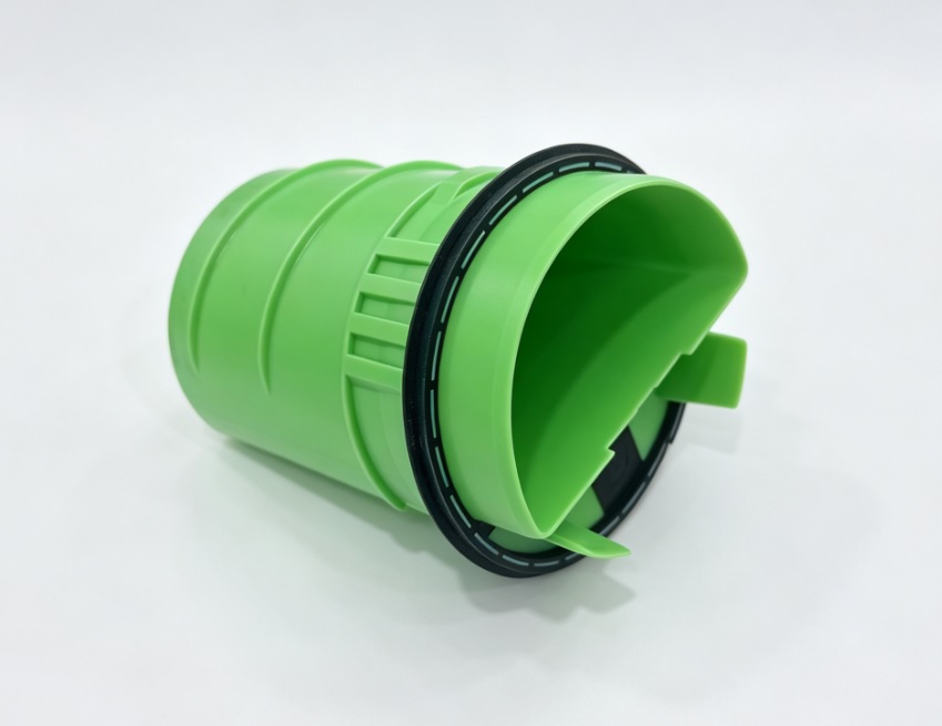
Zweikomponenten-Spritzgießform für 2-Material-Teile (2K-Form)
Zwei Materialien. Ein Formgebungszyklus. Ein fertiges Teil.
Konzipiert für Produkte, die Soft-Touch-Oberflächen, integrierte Dichtungen oder ein zweifarbiges Erscheinungsbild benötigen – ohne zusätzlichen Montageaufwand.
Konzipiert für Produkte, die Soft-Touch-Oberflächen, integrierte Dichtungen oder ein zweifarbiges Erscheinungsbild benötigen – ohne zusätzlichen Montageaufwand.
- Kleben und manuelle Montage ersetzen
- Das Risiko von Montagefehlern verringern
- Unterstützung von DFM, Moldflow, Werkzeugbau und Bemusterung
- Lösen Sie Verbindungsprobleme mit professionellem 2K-Spritzguss
1. Produktübersicht
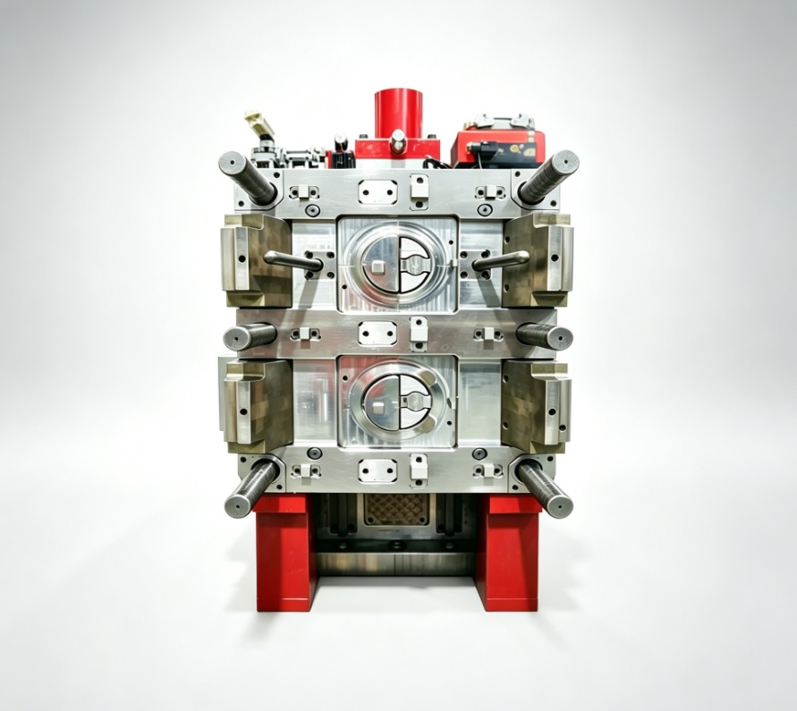
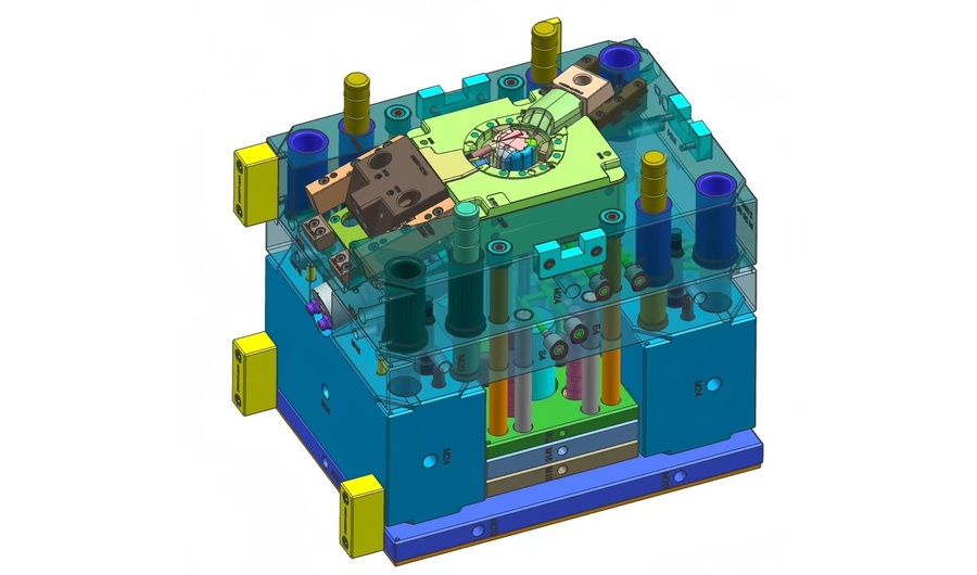
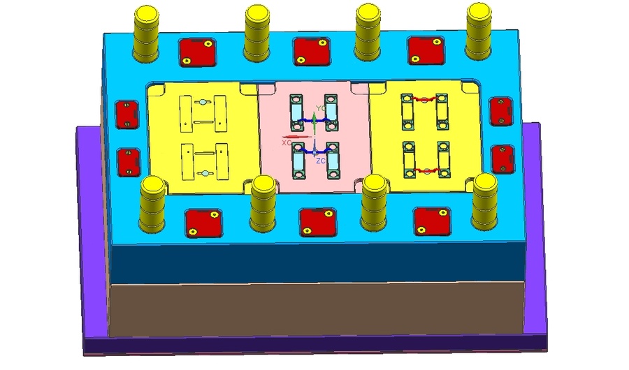
A two-shot injection mold—also called a 2K mold or multi-component mold—produces plastic parts composed of two different materials or colors in a single molding cycle on a dedicated two-shot injection machine with dual injection units. In the typical rotary platen configuration, the first material injects into cavity set A, then the rotary platen indexes 180 degrees, moving the shot-1 part into cavity set B where the second material injects directly onto or around it. The engineering challenge lies in three areas: indexing precision so the shot-1 part seats perfectly in cavity B every time, shut-off surfaces that withstand second-shot injection pressure without flashing, and material pair selection that ensures reliable bonding. At XINKEY MOULD, we design 2K molds around your specific material combination—whether PP+TPE for power tool grips, PC+ABS for enclosures, PMMA+PC for automotive lenses, or PA+TPU for medical seals.
2. Welche Probleme kann dieses Produkt lösen?
Blitz an der Second-Shot-Schnittstelle
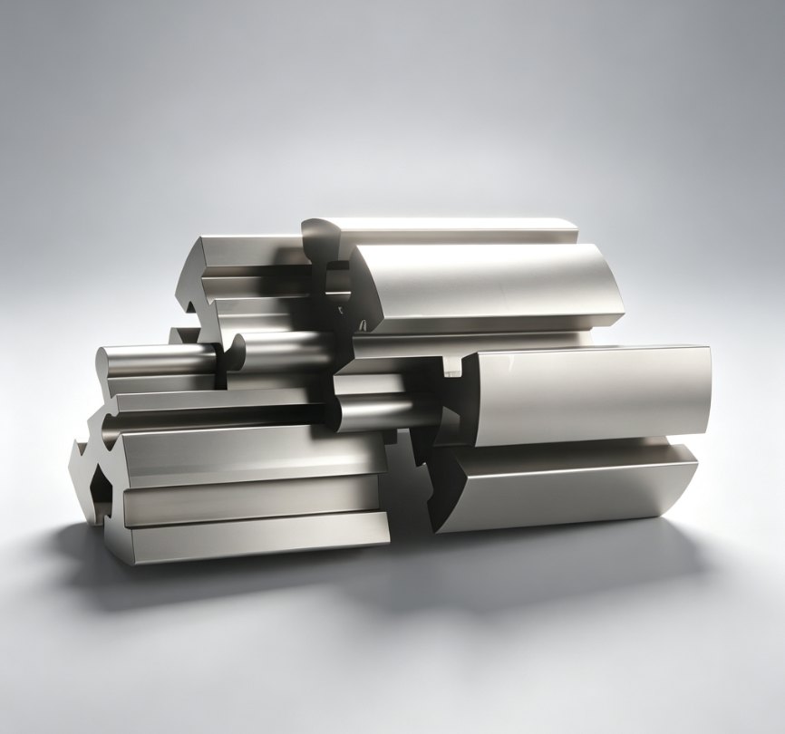
The most common defect in 2K molding: second material bleeds past the shut-off surface and covers cosmetic areas of the first material. This happens when shut-off steel does not perfectly match the shot-1 part profile—due to thermal expansion mismatch or shrinkage. XINKEY MOULD designs shut-off surfaces with 0.02-0.03mm interference fit at operating temperature, factors in thermal expansion coefficients of both materials, and uses mold flow to verify that injection pressure does not open the shut-off during fill.
Schlechte Haftung zwischen inkompatiblen Materialien
Not every pair of thermoplastics bonds well. PP and TPE bond through mechanical interlocking if the interface is properly designed, but PP and PA will delaminate without a tie layer. XINKEY MOULD’s DFM review includes a material compatibility assessment based on your target material pair, and we advise on chemical bonding, mechanical interlock, or tie-layer strategy before tooling starts.
Indexierungsfehler nach thermischer Zyklisierung
Eine Rotationsform wird über Stunden hinweg stark erhitzt. Stahl dehnt sich aus, der Indexiermechanismus verschleißt, und selbst bei perfekter Ausrichtung während der Einrichtung kann sich die Position nach 8 Stunden Dauerproduktion um 0,05 mm verschieben. Dies führt zu ungleichmäßiger Wandstärke beim zweiten Spritzvorgang oder sichtbaren Farbversätzen. Unsere 2K-Formen verwenden gehärtete Positionierverriegelungen zwischen der rotierenden und der stationären Hälfte sowie verschleißfeste Führungsstifte, die die Indexiergenauigkeit über die gesamte Lebensdauer der Form auf 0,02 mm genau gewährleisten.
3. Typische Anwendungen
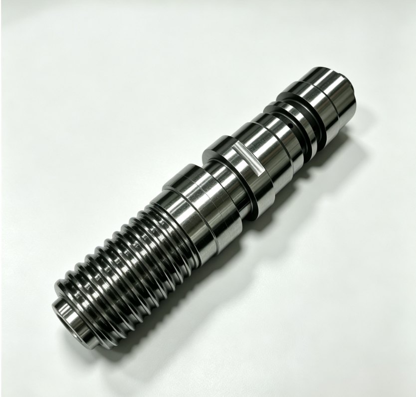
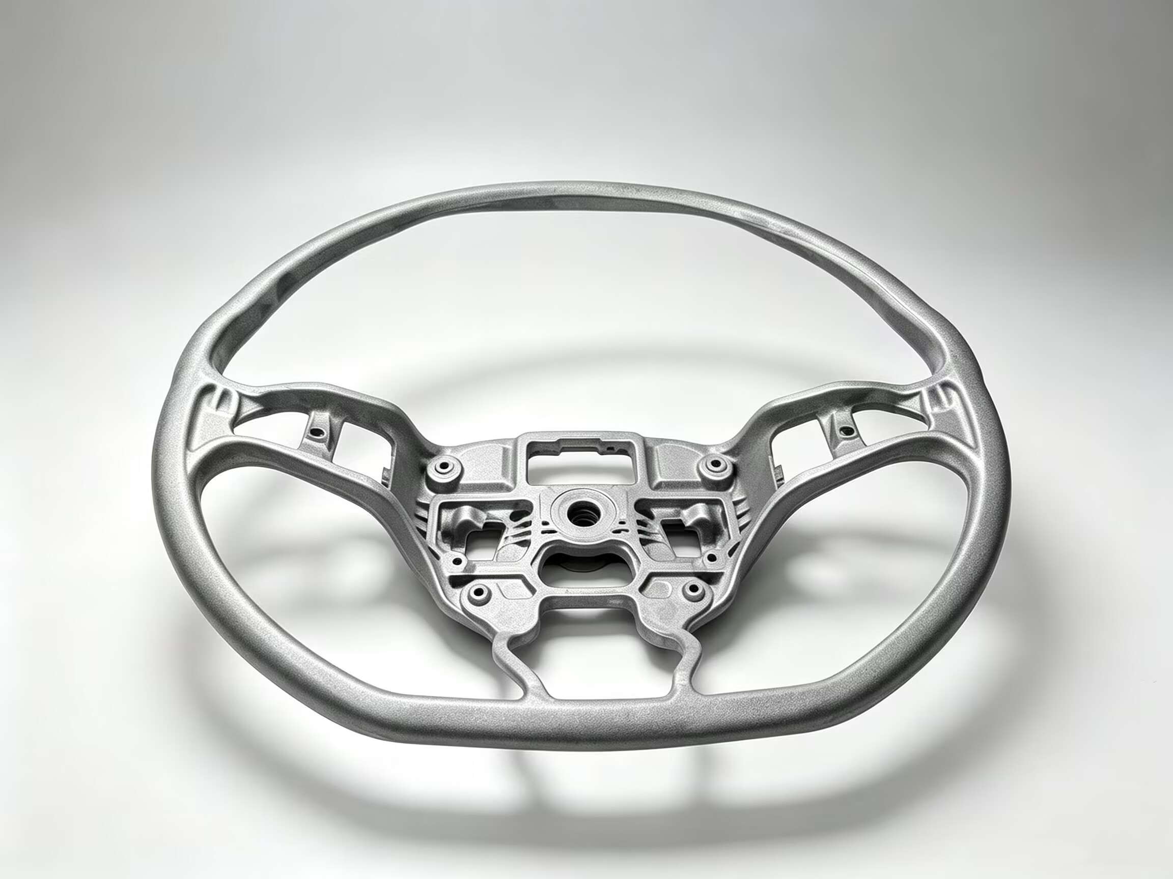
Soft-Touch-Werkzeuggriffe und Elektrowerkzeuggriffe
Ein stabiler PP- oder PA-Strukturkern wird mit TPE oder TPU umspritzt, um ergonomischen Halt und Vibrationsdämpfung zu gewährleisten. Typischerweise werden 2+2- oder 4+4-Kavitätenkonfigurationen verwendet. Entscheidend ist ein sauberer, spaltfreier Übergang zwischen hartem und weichem Material an der Trennlinie – sichtbar für den Endnutzer auf jeder Grifffläche.
Kfz-Scheinwerferlinsen und -gehäuse
Zweifarbige Fahrzeugleuchten – gelbes Blinklicht im einen Durchgang, rotes oder klares Licht im zweiten – werden als ein einziges, einteiliges Bauteil gefertigt. Die optischen Anforderungen erhöhen die Komplexität: Die Grenzfläche der beiden Materialien muss frei von Blasen, Verzerrungen und inneren Spannungen sein, die die Lichtdurchlässigkeit beeinträchtigen oder Blendpunkte erzeugen könnten. Gängige Materialpaare: PMMA und PC.
Dichtungen und Komponenten für Fluidwege in Medizinprodukten
Das starre Gehäuse aus PP oder COC mit integrierter TPE-Dichtung wird im zweiten Spritzgussverfahren hergestellt und gewährleistet so einen leckagefreien Flüssigkeitsweg ohne separate Dichtungsmontage. Es wird häufig bei medizinischen Einwegprodukten, Inhalationskomponenten und diagnostischen Verbrauchsmaterialien eingesetzt, da der Wegfall eines manuellen Montageschritts Kosten senkt und die Kontaminationskontrolle verbessert.
Tasten und Tastaturen für Unterhaltungselektronik
Harte Tastenkappen aus PC oder ABS mit weichen TPE-Knöpfen, die im zweiten Produktionsschritt durch die Tastenkappe hindurchgeformt werden und so für taktiles Feedback sowie Schutz vor Staub und Wasser sorgen. Das Material des zweiten Produktionsschritts muss präzise in die kleinen Öffnungen des ersten Produktionsschritts eingefüllt werden, ohne dass Material auf die sichtbare Oberseite ragt.
4. Spezifikationstabelle
| Artikel | Details |
| Formtyp | Zweikomponenten-Spritzgießform / 2K-Form / Mehrkomponentenform |
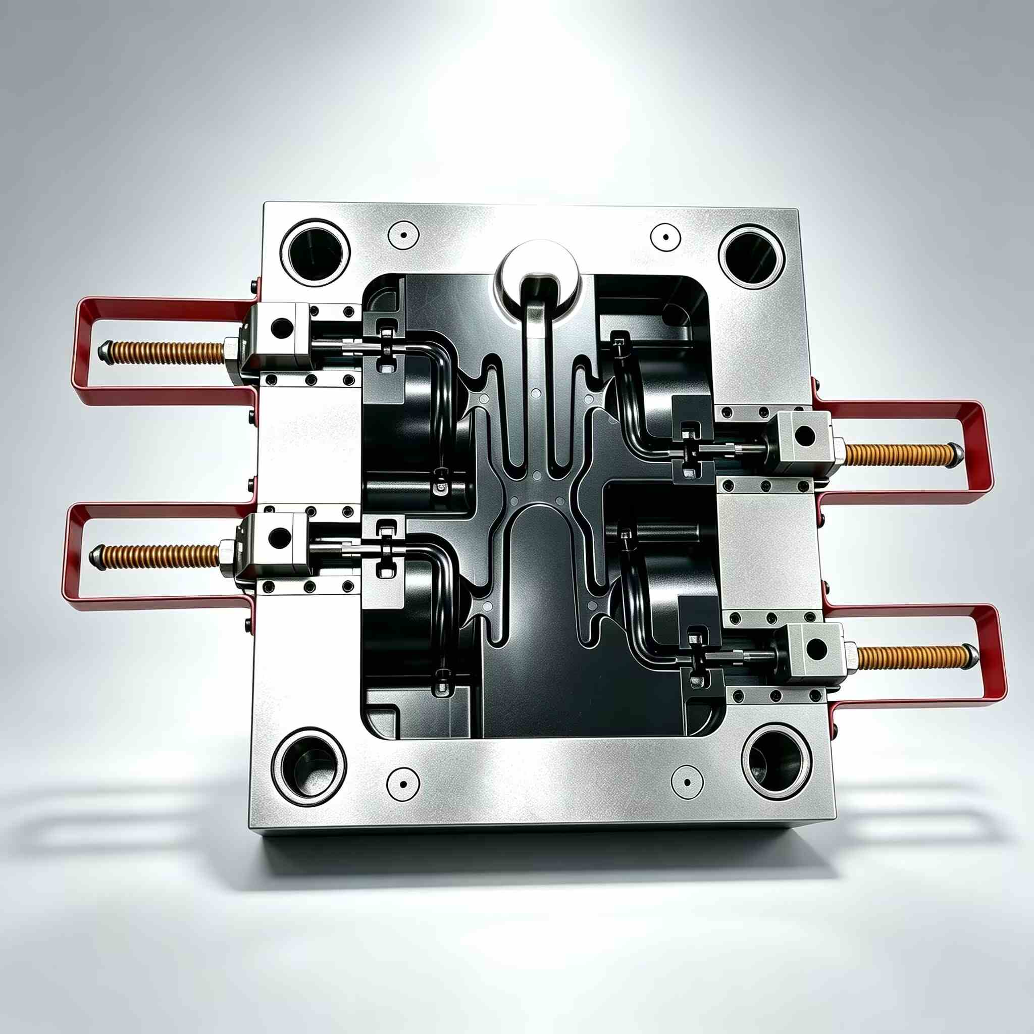
| Konfiguration | Drehteller (180°-Index), Kernrückseite oder Robotertransfer |
| Beispiele für Materialpaare | PP + TPE, PA + TPU, PC + ABS, PMMA + PC, PBT + LSR |
| Bindungsmechanismus | Chemische Bindung, mechanische Verzahnung oder Haftschicht (pro Materialpaar) |
| Indexierungsgenauigkeit | ≤0,02 mm wird über die gesamte Lebensdauer der Form beibehalten |
| Hohlraumbereich | Typischerweise 1+1 bis 4+4; größere Konfigurationen werden pro Projekt evaluiert. |
| Formstahl | H13 / S136 für hohe Stückzahlen; D2 Einsätze an Absperrflächen; P20 für Prototypen |
| Kühlung | Unabhängige Schaltkreise für Hohlraum A und Hohlraum B (unterschiedliche Materialtemperaturen) |
| Zykluszeitvorteil | 30–50 % Reduzierung gegenüber zwei separaten Formgebungsverfahren plus Montage |
| Designunterstützung | DFM, Materialverträglichkeitsanalyse, Formfüllanalyse für beide Schüsse, FEM der Absperrfläche |
| Testunterstützung | T1-Probenahme für beide Schüsse, Haftfestigkeitsprüfung, Querschnitts-Grenzflächenanalyse |
5. Projektprozess & Qualitätskontrolle
Phase 1: Materialpaaranalyse
Aktion:Prüfen Sie die vorgeschlagene Materialkombination hinsichtlich chemischer Kompatibilität, Überlappung der Schmelztemperaturen, Schrumpfungsdifferenz und Bindungsmechanismus. Empfehlen Sie gegebenenfalls Anpassungen der Materialpaarung.
QC-Fokus:Materialverträglichkeitshinweis: Empfehlung zur Haftungsprüfmethode, Verarbeitungsfenster (Temperaturbereiche für beide Materialien), Schrumpfungskompensationswerte für jeden Kavitätensatz.
Phase 2: Werkzeugkonstruktion & Abschalttechnik
Aktion:3D-Formkonstruktion mit Absperrflächen, modelliert mit einer Überdeckung von 0,02–0,03 mm. FEA der Absperrung unter dem Druck des zweiten Spritzvorgangs. Konstruktion eines Dreh- oder Kernrückseiten-Indexiermechanismus.
QC-Fokus:Bericht zur Überprüfung von Abschaltstörungen. Kinematische Simulation der Indexierungsbewegung. Überprüfung des unabhängigen Kühlkreislaufdesigns.
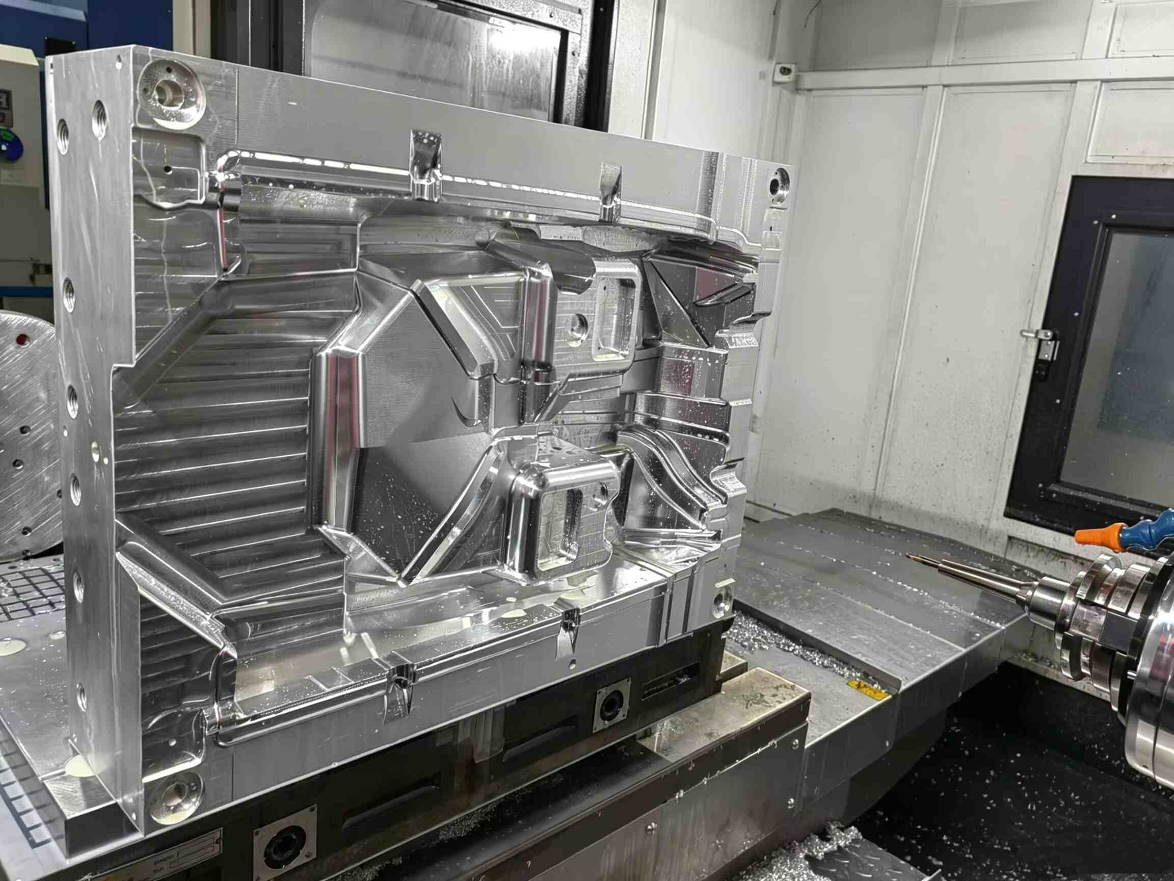
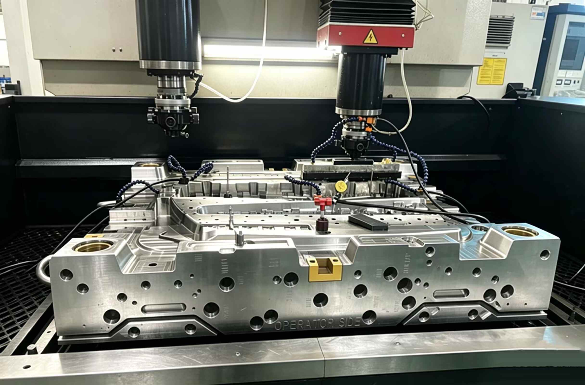
Phase 3: Präzisionsbearbeitung
Aktion:Die Absperrflächen wurden präzisionsgeschliffen, um die Toleranzen zu erfüllen. Die Kavitätensätze A und B wurden mit einer Bezugsgenauigkeit von 0,01 mm bearbeitet. Die Verschleißflächen wurden gehärtet.
QC-Fokus:CMM-Verifizierung der Absperrprofile. Überprüfung der Ausrichtung der Verriegelungsposition. Messung der Oberflächenrauheit an kosmetischen Kavitätenbereichen.
Phase 4: Montage- und Indexierungsprüfung
Aktion:Vollständige Montage mit eingebautem Dreh- oder Kernrückstellmechanismus. Manueller Indexiertest: 100 Zyklen mit Messung der Ausrichtungsgenauigkeit mittels Messuhr.
QC-Fokus:Bericht zur Wiederholgenauigkeit der Indexierung: Ausrichtungsabweichung alle 10 Zyklen erfasst. Überprüfung des Verriegelungseingriffs. Druckprüfung des Wasserkreislaufs: 8 bar/30 min.
Phase 5: T1-Studie (Beide Impfungen)
Aktion:Form auf einer 2K-Spritzgießmaschine. Die Parameter für den ersten Schuss wurden optimiert, anschließend die Parameter für den zweiten Schuss, um eine vollständige Füllung und optimale Haftung zu gewährleisten. Die Teile wurden nach Stabilisierung des Prozesses beprobt.
QC-Fokus:Überprüfung der zweiten Schussfüllung (keine unvollständigen Schüsse, kein Grat beim Abschalten). Haftfestigkeitsprüfung an Musterteilen (Schäl- oder Scherprüfung nach vereinbarter Methode). Maßbericht für beide Materialien. Querschnitt zur Überprüfung der Grenzflächenqualität.
Phase 6: Abschließende Prüfung & Lieferung
Aktion:Abschließende Reinigung, Rostschutz, Verpackung mit Ausrichtungsprüfbericht, Prozessparameterblatt für beide Einspritzeinheiten und Ersatz-Absperreinsatzsatz.
QC-Fokus:Vollständige Dokumentation. Video zur Formprüfung. Einrichtungsanleitung für die Maschine des Käufers. Wartungsplan für den Indexiermechanismus und den Austausch des Absperreinsatzes.
6. Why Choose XINKEY MOULD
Materialkombinationskompetenz
Wir haben 2K-Formen für PP+TPE-Griffe, PC+ABS-Gehäuse, PMMA+PC-Linsen und PA+TPU-Dichtungen hergestellt. Dadurch verfügen wir über fundierte Produktionsdaten zu den gängigsten Materialkombinationen. Wir schätzen die Haftfestigkeit nicht ein, sondern entwickeln die Grenzflächengeometrie und das Prozessfenster auf Basis bewährter Erfahrung.
Abschaltmechanismus, der auch unter Druck hält
Die Trennzone zwischen dem ersten und zweiten Spritzvorgang ist die häufigste Schwachstelle von 2K-Formen. Unsere Trennzonenkonstruktion nutzt FEM-Simulationen, um sicherzustellen, dass sich die Stahloberfläche unter dem Einspritzdruck des zweiten Spritzvorgangs nicht aufwölbt. Wir verwenden gehärtetes D2 oder ein vergleichbares Material in den Trennzonen und konstruieren austauschbare Trenneinsätze für eine lange Lebensdauer.
Produktionsreifes Indexierungsdesign
Eine 2K-Form, die beim Einrichten präzise indexiert, aber nach 1.000 Zyklen driftet, ist kein Produktionswerkzeug. Wir verwenden gehärtete Führungskomponenten, konische Verriegelungen und verschleißfeste Buchsen an allen beweglichen Ausrichtungsflächen. Jede Form wird mit einem Prüfbericht zur Indexiergenauigkeit ausgeliefert, der die Ausrichtungsgenauigkeit über mehr als 100 manuelle Zyklen dokumentiert.
Vollständige DFM-Analyse vor Werkzeugbaubeginn
Unsere DFM-Analyse umfasst die Materialpaarkompatibilität, die Angusslage für beide Schüsse, den Kühlbedarf für jedes Material, die Abschaltstrategie und das Prozessfenster, in dem beide Materialien zusammen geformt werden können. Diese frühzeitige Entwicklungsarbeit vermeidet die Entdeckung grundlegender Konstruktionsprobleme zum Zeitpunkt T1, wenn der Stahl bereits zugeschnitten ist.
7. Häufig gestellte Fragen (FAQ)
Frage 1: Worin besteht der Unterschied zwischen Zweikomponenten-Spritzgießen und Umspritzen mit Einlegeteilen?
Das Zweikomponenten-Spritzgießen fertigt das gesamte Bauteil in einem Maschinenzyklus – beide Materialien werden nacheinander in dieselbe Form auf einer 2K-Maschine eingespritzt. Beim Umspritzen mit Einlegeteilen wird ein zweites Material über ein vorgefertigtes Bauteil gespritzt, das manuell oder robotergestützt in die Form eingelegt werden muss. Das Zweikomponenten-Spritzgießen bietet kürzere Zykluszeiten und eine bessere Prozesskontrolle; das Umspritzen mit Einlegeteilen ist flexibler für Kleinserien oder nicht spritzgegossene Substrate.
Frage 2: Verbinden sich alle Thermoplaste chemisch in einer 2K-Form?
Nein. Manche Materialpaare verbinden sich chemisch – TPE-Formulierungen verbinden sich mit PP, PC mit ABS aufgrund ähnlicher chemischer Strukturen. Andere Paare wie PP und PA verbinden sich nicht chemisch und erfordern eine mechanische Verzahnung, die in die Materialzusammensetzung des Bauteils integriert ist. Wir analysieren Ihr Materialpaar während des DFM-Prozesses und beraten Sie hinsichtlich der geeigneten Verbindungsstrategie.
Frage 3: Welche Maschinenkonfiguration ist für das Zweikomponenten-Spritzgießen erforderlich?
Eine Zweikomponenten-Spritzgießmaschine (2K) mit zwei unabhängigen Spritzeinheiten und Drehteller oder Kernrückführung. Falls Sie keine 2K-Maschine besitzen, können wir besprechen, ob das Umspritzen mit einer Standardmaschine eine praktikable Alternative darstellt oder ob das Projektvolumen die Investition in eine 2K-Maschine rechtfertigt.
Frage 4: Kann eine 2K-Form Teile aus mehr als zwei Materialien herstellen?
Es gibt zwar Drei- (3K) und Vierkomponenten-Formen, diese erfordern jedoch spezielle Mehrstationenmaschinen und sind deutlich komplexer. Für die meisten Anwendungen ist ein gut konzipiertes Zweikomponenten-Verfahren ausreichend. Sollte Ihr Bauteil tatsächlich drei verschiedene Materialien benötigen, prüfen wir gerne die Machbarkeit anhand Ihrer Produktionsanlagen und Ihres geplanten Produktionsvolumens.
Frage 5: Welche Faktoren beeinflussen die Kosten einer 2K-Form?
Die wichtigsten Kostentreiber sind: Komplexität der Absperrfläche, Anzahl der Kavitäten (2K-Formen haben typischerweise weniger Kavitäten als Werkzeuge aus einem einzigen Material, da jede Kavitätengruppe eine unabhängige Kühlung und Ausrichtung erfordert), Schwierigkeit der Materialpaarung und Art des Indexiermechanismus. Die Rotationsplatte ist am gebräuchlichsten; Kernrückführung und Robotertransfer weisen unterschiedliche Kostenprofile auf.
Produkte
CNC-Fräsen & Drehen
5-Achs-CNC-Fräsen und -Drehen – Präzise 5-Achs-Fräs- und Drehbearbeitung für Prototypen und Serienfertigung von Metall- und Kunststoffbauteilen. Mehrseitenfräsen in einer Aufspannung kombiniert mit CNC-Drehen auf einer Plattform eliminiert den Teiletransfer zwischen Maschinen und ermöglicht eine Positioniergenauigkeit von ±0,01 mm ohne Toleranzanstieg zwischen den Aufspannungen. Umfassende CNC-Bearbeitung für Aluminium, Stahl, Edelstahl, Messing, POM, PEEK und technische Kunststoffe.
Erfahren Sie mehr
Draht durchtrennt
Drahterodieren – Präzisions-Drahterodieren für komplexe 2D-Profile, eng tolerierte Werkzeugkomponenten und gehärtete Stahlteile, die nicht gefräst werden können. Erreicht eine Genauigkeit von ±0,003 mm und eine Oberflächenrauheit von Ra 0,2 µm bei Werkzeugstahl, Hartmetall und leitfähigen Hartmetallen. Kernleistung für Spritzgusseinsätze, Stanzwerkzeugkomponenten und Präzisionslehren.
Erfahren Sie mehr
5-Achs-CNC-Bearbeitung
5-Axis CNC Machining — Simultaneous 5-axis contouring for complex 3D surfaces, undercut geometries, and multi-sided parts in a single setup. Eliminates multiple fixturing operations and cumulative tolerance error. Ideal for impellers, turbine blades, orthopedic implants, and injection mold 3D cavity surfaces.
Erfahren Sie mehr
EDM-Funkenerosion
Funkenerosion – Präzisions-Senkerodierverfahren zur Bearbeitung von Hohlräumen in gehärtetem Werkzeugstahl mit scharfen Innenkanten, tiefen Rippen und komplexen 3D-Geometrien. Dabei werden speziell gefertigte Graphit- oder Kupferelektroden eingesetzt, um Bereiche zu bearbeiten, die mit rotierenden Schneidwerkzeugen nicht erreichbar sind. Kernverfahren für Spritzgussformen, Druckgusswerkzeuge und Sacklöcher mit einer Genauigkeit von ±0,005 mm.
Erfahren Sie mehr
Zinkdruckgussform & Teile
Zinkdruckgussform – Präzisionswerkzeug für die Warmkammerfertigung von Zinklegierungsbauteilen mit hoher Fertigungsgeschwindigkeit. Konzipiert für die dünnwandige, endformnahe Produktion von Automobilverkleidungen, Elektronikgehäusen und Konsumgüterhardware mit Zykluszeiten von nur 3–5 Sekunden und gleichbleibender Oberflächenqualität im Gusszustand.
Erfahren Sie mehr
Magnesium-Druckgussformteile
Magnesium-Druckgussform – Kaltkammer-Hochdruckwerkzeug, entwickelt für die Magnesiumlegierungen AZ91D, AM60B und AS41B. Speziell für den Leichtbau in der Automobilindustrie, Gehäuse für die Luft- und Raumfahrt sowie tragbare Elektronik, wo jedes Gramm zählt. Ermöglicht die Herstellung von Bauteilen in Endform mit einem Gewicht von 1,8 g/cm³ – 33 % leichter als Aluminium und 75 % leichter als Stahl.
Erfahren Sie mehr
Neueste Nachrichten

- 29. Mai 2026
Warum Produktentwicklungsteams häufig mit Schimmelproblemen zu kämpfen haben – und wie sich teure Verzögerungen vermeiden lassen
In vielen Produktentwicklungsprojekten liegt der Fokus zunächst auf dem Produkt selbst – Aussehen, Funktionalität, Elektronik und Benutzererfahrung.
Dieser Teil schreitet in der Regel schnell voran.
Die eigentlichen Probleme beginnen oft erst später, wenn die Konstruktion in die Werkzeugfertigung und Produktion übergeht.
Der Grund ist einfach: Die meisten Produktentwickler sind keine Werkzeugbauer.
Sie verstehen das Produkt zwar sehr gut, verfügen aber nicht über die Erfahrung in der Konstruktion von Spritzgussformen, der Werkzeugplanung und der produktionsorientierten Optimierung von Kunststoffteilen. Daher stoßen viele neue Produkte auf dieselben Probleme:
Schwierig zu formende Produktstrukturen
Übermäßige Hinterschnitte und unzureichende Entformungsschrägen
Einfallstellen und Verformungen nach dem Spritzgießen
Ungleichmäßige Füllung und unvollständige Füllung
Schwieriges Entformen
Mehrere Werkzeugmodifikationen nach dem T1-Test
Verzögerte Produkteinführung
Steigende Werkzeug- und Entwicklungskosten
In vielen Fällen wird die Werkzeugentwicklung zum Problemlöser statt zur Lösung für die Fertigungsprobleme.
Genau hier ist professionelle Unterstützung im Werkzeugbau unerlässlich. One-Stop Mold Engineering & Fertigungsunterstützung
Wir bieten Ihnen eine umfassende Komplettlösung:
Optimierung der Produktstruktur
DFM-Analyse
Formenströmungssimulation
Komplette Werkzeugkonstruktion
Werkzeugbau und Probeformen
Durch die Integration von Produktentwicklung und Werkzeugbau in einen Workflow helfen wir unseren Kunden, Entwicklungsrisiken zu minimieren und Produkte schneller in die Serienproduktion zu überführen.
1. Optimierung der Produktstruktur für die Serienfertigung
Ein Produktdesign, das auf dem Bildschirm gut aussieht, funktioniert in der realen Produktion nicht immer optimal. Viele Kunststoffteile werden zunächst konstruiert, ohne folgende Aspekte zu berücksichtigen:
Konstante Wandstärke
Anforderungen an den Entformungswinkel
Einschränkungen der Rippenstruktur
Machbarkeit von Hinterschnitten
Einfluss der Angusslage
Risiken von Abkühlungsverformungen
Diese Probleme treten möglicherweise nicht während der CAD-Konstruktion auf, können aber bei der Werkzeugherstellung und den Probeformen schnell hohe Kosten verursachen. Unser Ingenieurteam prüft die Produktstruktur, bevor die Werkzeugkonstruktion beginnt. Ohne das Aussehen oder die funktionalen Anforderungen des Produkts zu verändern, optimieren wir die Struktur für die Spritzgussfertigung. Dies hilft, häufige Probleme beim Formenbau zu vermeiden, wie z. B.:
Einfallstellen
Schleifspuren
Verzug
Fehlfüllungen
Spannungsmarken
Schwieriges Entformen
Frühe Optimierung reduziert Nacharbeiten am Werkzeug erheblich und verbessert die Erfolgsquote beim ersten Schuss.
2. Professionelle DFM-Analyse (Design for Manufacturability)
Vor Beginn der Werkzeugfertigung erstellen wir einen vollständigen DFM-Bericht in englischer Sprache, der Kunden hilft, die Herstellbarkeit des Produkts vollständig zu verstehen.
Der Bericht beinhaltet:
Vorschläge für Trennlinien
Empfehlungen für die Angusslage
Analyse potenzieller Hinterschneidungen
Überprüfung des Entformungswinkels
Risikobereiche für Formfehler
Empfehlungen für die Werkzeugstruktur
Erste Vorschläge für das Werkzeugkonzept
Anstatt Probleme erst nach dem Stahlschneiden zu entdecken, können Kunden Risiken frühzeitig erkennen und fundierte Entscheidungen treffen, bevor die Produktion beginnt.
Dies verkürzt die Kommunikationszyklen und hält die Projektrisiken unter Kontrolle. Für Kunden im Ausland, insbesondere Startups und Hardwareunternehmen ohne eigene Werkzeugentwicklung, wird die DFM-Analyse zu einer wichtigen Brücke zwischen Produktentwicklung und Fertigung.
3. Formfüllanalyse vor Werkzeugbau
Einer der teuersten Fehler im Werkzeugbau ist die Entdeckung von Produktionsfehlern nach der Fertigstellung des Werkzeugs.
Um dies zu vermeiden, führen wir vor der Werkzeugproduktion eine Formfüllsimulation durch.
Mithilfe von Spritzgusssimulationssoftware können wir Probleme wie die folgenden vorhersagen:
Schweißnähte
Lufteinschlüsse
Füllungleichgewicht
Verzug
Kühlprobleme
Risiken des Einspritzdrucks
Dies ermöglicht es uns, sowohl die Produktstruktur als auch die Werkzeugkonstruktion vor Beginn der Bearbeitung zu optimieren.
In vielen Projekten trägt die Formfüllanalyse dazu bei, wiederholte Werkzeugmodifikationen zu reduzieren und die Anzahl der erforderlichen Probeläufe zu verringern.
Bei komplexen Kunststoffteilen kann dieser Schritt Wochen an Entwicklungszeit einsparen und die gesamten Werkzeugkosten deutlich senken.
4. Vollständig standardisierte Werkzeugkonstruktion nach europäischen Normen
Eine stabile Werkzeugkonstruktion hängt nicht allein von der Bearbeitungsqualität ab. Die Werkzeugkonstruktion selbst bestimmt die langfristige Zuverlässigkeit.
Unser Werkzeugkonstruktionsprozess orientiert sich an europäischen Werkzeugnormen, darunter:
HASCO-Normen
Meusburger-Normen
Wir bieten Ihnen die komplette Werkzeugkonstruktion inklusive:
Schneid- und Auswerferkonstruktion
Heißkanalsysteme
Kühlsystemauslegung
Auswerfersystem
Werkzeugbaugruppe
3D-Werkzeugbaugruppendateien
2D-Bearbeitungszeichnungen
Vollständige Stücklisten
Alle Zeichnungen sind standardisiert für eine effiziente Fertigung, zukünftige Wartung und langfristige Produktionsstabilität.
Dies ist besonders wichtig für Kunden, die Werkzeuge in Exportqualität und gleichbleibende Produktionsstandards benötigen.
5. Werkzeugbau, Probeformen & schlüsselfertige Lieferung
Konstruktion allein genügt nicht.
Ein erfolgreiches Werkzeugprojekt hängt auch maßgeblich von Bearbeitungsgenauigkeit, Montageerfahrung und Probeformen ab.Fertigungskompetenz.
Mit unserer hauseigenen Werkzeugfertigung bieten wir umfassende Dienstleistungen im Bereich Werkzeugbau an, darunter:
CNC-Bearbeitung
EDM-Bearbeitung
Werkzeugmontage
Probeformen
Werkzeugkorrektur und -optimierung
Unterstützung bei Kleinserienfertigung
Kunden müssen sich nicht mit mehreren Lieferanten für Design, Bearbeitung, Tests und Modifikationen abstimmen.
Alles wird von einem integrierten Team abgewickelt.
Dies verbessert die Kommunikationseffizienz erheblich und verkürzt die Projektlaufzeit.
Warum viele Unternehmen externe Unterstützung im Werkzeugbau wählen
Viele Startups, Produktdesignfirmen und kleine bis mittelständische Hardwareunternehmen verfügen nicht über eine eigene Werkzeugbauabteilung.
Daher stehen Produktteams oft vor Herausforderungen wie:
Unklarheit über die Spritzgießbarkeit des Produkts
Schwierigkeiten bei der Bewertung von Angeboten von Werkzeuglieferanten
Wiederholte Werkzeugmodifikationen
Unklare Ursachen bei Tests
Lange Entwicklungsverzögerungen
Durch die Zusammenarbeit mit einem erfahrenen Partner für Werkzeugbau und -fertigung lassen sich diese Probleme deutlich früher im Prozess lösen.
Wir agieren als externe Erweiterung Ihres Entwicklungsteams im Bereich Formenbau und vereinen Produktoptimierung, Formenbau und Fertigung in einem durchgängigen Workflow.
Der wahre Wert des integrierten Formenbaus
Ein guter Formenlieferant bietet mehr als nur die reine Stahlverarbeitung.
Der wahre Mehrwert liegt darin, Kunden zu helfen, Fertigungsfehler von vornherein zu vermeiden. Mit integrierter Unterstützung in den Bereichen Engineering und Fertigung können Unternehmen:
Werkzeugrisiken reduzieren
Produktentwicklungszyklen verkürzen
Erfolgsquoten bei ersten Formenversuchen verbessern
Änderungskosten senken
Serienreife beschleunigen
Stabil und langfristig in der Produktion bleiben
Für Unternehmen, die europäische und internationale Märkte bedienen, ist standardisierter Formenbau nicht nur ein Qualitätsvorteil – er wirkt sich direkt auf Produktionsstabilität, Lieferzeiten und die Gesamtprojektkosten aus.
Suchen Sie Unterstützung im Bereich Spritzgussformenbau? Bei der Entwicklung neuer Kunststoffprodukte stellen viele Teams fest, dass ihnen die internen Kompetenzen im Formenbau fehlen – und genau hier setzen wir an. Wir bieten Ihnen ein umfassendes Leistungsspektrum im Bereich Spritzguss aus einer Hand, um eine reibungslose Serienproduktion zu gewährleisten. Unsere Unterstützung umfasst alle wichtigen Phasen: Produktoptimierung, DFM-Analyse, Werkzeugkonstruktion und -herstellung sowie laufende Produktionsunterstützung.

- 18. Mai 2026
Jenseits der Welle: So beseitigen Sie Fließmarken und schützen Ihre Oberflächenbeschaffenheit
Fließmarken beim Spritzgießen | Ursachen, Fehlerbehebung und Präventionsmethoden zur Verbesserung der Teilequalität
Seien wir ehrlich: Nichts ist so schädlich für die Produktion wie Fließmarken. Selbst ein perfekt gefülltes und maßgenaues Teil mit welligen Linien oder unschönen Streifen auf der Oberfläche landet direkt im Ausschuss. In Branchen wie der Automobil- oder Unterhaltungselektronik, wo die Optik entscheidend ist, sind diese geisterhaften Muster ein absolutes Ausschlusskriterium. Das Ärgerlichste daran? Fließmarken sind meist rein ästhetischer Natur. Das Teil ist strukturell einwandfrei, gilt aber in den Augen des Kunden trotzdem als Ausschuss. Wenn Sie es satt haben, Ihre Gewinnmargen durch Ausschuss zu schmälern, müssen Sie genau verstehen, warum die Schmelze im Werkzeug nicht richtig fließt.
Was passiert eigentlich im Formhohlraum?
Im Kern ist eine Fließmarke die dauerhafte Aufzeichnung einer zögerlichen Schmelzfront.
Stellen Sie sich die Schmelzfront beim Auftreffen auf das Werkzeug vor: Diese äußere Schicht befindet sich in einem ständigen Wettlauf mit dem kalten Stahl der Form. Ist der Materialfluss zu träge oder fehlt die nötige Wärme, gleitet die Vorderkante nicht – sie stockt.
Wenn das heißere Harz dahinter schließlich nach vorne drängt, hinterlässt es eine dauerhafte Narbe auf der Oberfläche. Diese wellenförmige Linie oder das ringförmige Muster ist im Grunde eine visuelle Karte eines Materialflusses, der um jeden Zentimeter gekämpft hat. Es handelt sich nicht nur um einen unschönen Fehler; es ist ein eindeutiger Beweis dafür, dass Ihr Material dem Temperaturdruck Ihres Werkzeugs nicht standhält.
Erfahrungsgemäß treten diese Spuren fast immer an denselben Stellen auf.
Häufige Stellen für Fließmarken
In den meisten Fällen treten Fließmarken in der Nähe von folgenden Bereichen auf:
Angussbereiche
Übergänge von dünnen zu dicken Wänden
Scharfe Ecken
Lange Fließwege
Bereiche mit plötzlichen Fließrichtungsänderungen
Aussehen von Fließmarken
Je nach Material und Werkzeugstruktur kann der Fehler wie folgt aussehen:
Wellenlinien
Halo-Ringe
Schlangenartige Streifen
Glanzunterschiede
Schattenmarkierungen
Auf glänzenden oder dunklen Teilen sind Fließmarken in der Regel leichter zu erkennen.
Warum entstehen Fließmarken?
In der Presse hängt alles von einem empfindlichen Gleichgewicht zwischen dem Fließverhalten der Schmelze und der Abkühlung des Werkzeugs ab. Sobald das Harz zu langsam fließt oder zu früh abkühlt, sind die Folgen sofort an der Oberfläche sichtbar.
1. Die Ursache: Zu langsame Einspritzgeschwindigkeit
Normalerweise überprüfen wir zuerst die Füllgeschwindigkeit.
Bei zu langsamer Einspritzung verlieren Sie quasi die Zeit. Die vordere Kante des Kunststoffs beginnt zu stocken und zu erstarren, während das heißere Material dahinter noch versucht, sich nach vorne zu drängen.
Dies führt zu einem „Stottereffekt“ an der Fließfront und hinterlässt die typischen wellenförmigen Unebenheiten auf der Oberfläche des Bauteils.
Dies tritt besonders häufig auf bei:
Dünnwandigen Bauteilen
Großen, flachen Oberflächen
Formen mit langem Fließweg
Lösung
Erhöhen Sie die Einspritzgeschwindigkeit schrittweise. Verwenden Sie eine mehrstufige Einspritzsteuerung. Halten Sie den Fülldruck konstant.
Ein schnellerer und gleichmäßigerer Füllvorgang reduziert sichtbare Fließmuster oft deutlich.
2. Zu niedrige Schmelztemperatur
Bei unzureichender Materialtemperatur steigt die Harzviskosität und der Fließwiderstand. Die Schmelze kann beim Durchfließen des Formhohlraums keine glatte Oberfläche bilden.
Niedrige Schmelztemperaturen verursachen häufig:
Ungleichmäßige Fließfronten
Streifenbildung an der Oberfläche
Ungleichmäßiger Glanz
Lösung
Zylindertemperatur vorsichtig erhöhen
Tatsächliche Schmelztemperatur überprüfen, nicht nur Maschineneinstellungen
Empfohlenen Verarbeitungsbereich des Harzlieferanten beachten
Verschiedene Materialien reagieren unterschiedlich auf Wärme. Technische Kunststoffe erfordern in der Regel eine präzisere Temperaturkontrolle als Standardharze.
3. Zu niedrige Werkzeugtemperatur
Eine kalte Werkzeugoberfläche führt dazu, dass die Schmelze beim Kontakt mit der Kavitätswand schnell erstarrt. Die Hautschicht bildet sich zu früh und unterbricht den gleichmäßigen Harzfluss.
Dieses Problem tritt häufig bei der Winterproduktion oder bei Werkzeugen mit ungleichmäßiger Kühlung auf.
Lösung
Werkzeugtemperatur erhöhen
Temperaturgleichmäßigkeit zwischen den Kavitätsabschnitten verbessern
Bei Bedarf Werkzeugtemperaturregler verwenden
Bei kosmetischen Teilen ist eine stabile Werkzeugtemperatur oft wichtiger als die Zyklusgeschwindigkeit.
4. Probleme mit der Angussgestaltung
Der Anguss ist im Wesentlichen der „Hals“ Ihres Werkzeugs.
Ist der Anguss zu eng oder falsch positioniert, fließt das Harz nicht in den Formhohlraum, sondern staut sich und erzeugt einen chaotischen und instabilen Fluss. Noch schlimmer: Zu kleine Angüsse wirken wie Hochdruckdüsen, die das Material mit übermäßiger Scherspannung bearbeiten und unschöne Streifen hinterlassen, die die Oberflächengüte beeinträchtigen.
Häufige Probleme mit Angüssen
Anguss zu klein
Falsche Angussposition
Einzelner Anguss bei großen Teilen
Plötzliche Flussausweitung nach dem Anguss
Lösung
Angussgröße nach Möglichkeit vergrößern
Angussposition zur Verbesserung der Flussbalance verändern
Mehrere Angüsse für größere Teile verwenden
Angusskanal optimieren
Optimale Angussgestaltung verbessertSowohl die Füllstabilität als auch die Oberflächenqualität werden beeinträchtigt.
5. Zu schnelle Wandstärkenänderungen
Wenn die Schmelze von einem dünnen in einen dickeren Bereich fließt, ändert sich die Fließgeschwindigkeit abrupt. Dieser Übergang kann das Oberflächenbild stören und sichtbare Fließlinien hinterlassen. Abrupte Wandstärkenänderungen erhöhen zudem die Kühlungleichmäßigkeit.
Lösung
Gleichmäßige Wandstärke beibehalten
Anfangs sanfte Übergänge statt abrupter Wandstärkensprünge verwenden
Fließbereiche mit geeigneten Radien versehen
Eine gute Teilekonstruktion reduziert viele Formfehler bereits vor Produktionsbeginn.
6. Unzureichende Entlüftung im Werkzeug
Eingeschlossene Gase im Formhohlraum können den Schmelzefluss behindern. Durch die Kompression der Luft kann die Kunststofffront stocken oder ihre Richtung leicht ändern, was zu Oberflächenfehlern führt. Obwohl Entlüftungsprobleme häufiger mit Brandspuren in Verbindung gebracht werden, können sie auch zu Fließspuren beitragen.
Lösung
Verstopfte Entlüftungsöffnungen reinigen
Bei Bedarf zusätzliche Entlüftungsöffnungen hinzufügen
Gasabfluss in der Nähe des Füllendes verbessern
Eine ordnungsgemäße Entlüftung sorgt für einen gleichmäßigen Materialfluss im gesamten Formhohlraum.
7. Materialfeuchtigkeit oder Harzprobleme
Einige technische Kunststoffe absorbieren schnell Feuchtigkeit aus der Luft. Feuchtes Material kann beim Einspritzen zu instabilem Schmelzverhalten führen und die Oberflächenqualität beeinträchtigen.
Inkonsistente Mahlgutanteile oder verunreinigtes Harz können ebenfalls Fließfehler verstärken.
Lösung
Hygroskopische Materialien korrekt trocknen
Feuchtigkeitsgehalt überwachen
Materialchargen konstant halten
Kontaminationsrisiko bei der Handhabung minimieren
Eine stabile Materialqualität ist essenziell für stabile Spritzgussergebnisse.
Effiziente Fehlerbehebung bei Fließmarken
Wenn Fließmarken auftreten, vermeiden Sie es, mehrere Parameter gleichzeitig zu ändern. Zufällige Änderungen erschweren die Fehlersuche.
Ein besserer Ansatz ist die schrittweise Überprüfung des Prozesses:
Schmelztemperatur bestätigen
Temperaturausgleich in der Form überprüfen
Einspritzgeschwindigkeit schrittweise erhöhen
Zustand von Anguss und Verteilerkanal prüfen
Entlüftungsbereiche prüfen
Wandstärkenauslegung überprüfen
Harzzustand beurteilen
Prozessaufzeichnungen aus früheren stabilen Produktionsläufen können ebenfalls helfen, Änderungen schneller zu erkennen.
Fließmarken bei der Formkonstruktion vermeiden
Vorbeugen ist immer günstiger als Heilen. Viele Probleme mit Fließmarken entstehen bereits bei der Teilekonstruktion oder Werkzeugentwicklung.
Empfohlene Konstruktionspraktiken
Verwenden Sie ausbalancierte Angusskanäle.
Achten Sie auf eine gleichmäßige Wandstärke.
Vermeiden Sie übermäßige Fließlängen.
Planen Sie die Entlüftungsstellen optimal ein.
Optimieren Sie die Angussposition frühzeitig.
Berücksichtigen Sie ästhetische Anforderungen bei der Werkzeugflussanalyse.
Wenn die Ästhetik entscheidend ist, müssen Sie dem Problem vorbeugen. Eine frühzeitige Werkzeugflusssimulation ist kein Luxus – sie ist der beste Weg, diese Oberflächenprobleme zu erkennen, bevor Sie überhaupt Stahl bearbeiten. Glauben Sie mir, es ist immer günstiger, eine Konstruktion am Bildschirm anzupassen, als ein gehärtetes Werkzeug zu schweißen und nachzubearbeiten, sobald es bereits in der Produktion ist.
Die Realität: Geben Sie sich nicht mit Schleifspuren zufrieden.
Es ist verlockend, eine Fließmarke als „rein kosmetisch“ abzutun, aber das ist ein riskantes Unterfangen. Diese wellenförmigen Muster sind meist ein eindeutiges Indiz dafür, dass der Prozess grundlegend aus dem Takt geraten ist.
Ob es sich nun um eine Temperaturabweichung oder einen zu eng anliegenden Anguss handelt – wenn Sie diese „Geistermuster“ an Ihren Teilen ignorieren, riskieren Sie, Ihre Gewinnmargen durch einen Berg an Ausschuss zu ruinieren. Fakt ist: Oberflächenprobleme lassen sich nicht einfach durch das Drehen an einem beliebigen Regler der Presse beheben. Wahre Qualität ist ein Alles-oder-Nichts-Prinzip – Werkzeugdesign, Füllbalance und Temperatur müssen perfekt aufeinander abgestimmt sein.
Hören Sie auf zu raten, finden Sie die eigentliche Ursache und beenden Sie das ständige Beheben von Problemen ein für alle Mal.
So kehren Sie zu einer stabilen und profitablen Produktion zurück.

- 11. Mai 2026
Leitfaden zur Fehlerbehebung bei Kurzschüssen im Spritzgussverfahren
Einleitung
Füllmaterialfehler sind ein Problem, mit dem die meisten Hersteller früher oder später beim Spritzgießen konfrontiert werden, insbesondere bei der Produktion dünnwandiger Kunststoffteile oder Komponenten mit langen Fließwegen. Manchmal erscheint der Spritzgießprozess völlig normal, doch die aus der Form kommenden Teile sind nicht vollständig ausgeformt. Es können fehlende Kanten, unvollständige Konturen oder Bereiche auftreten, in denen der Kunststoff das Ende des Formhohlraums nicht erreicht. Diese Art von Fehler bedeutet in der Regel, dass das geschmolzene Material seine Fließfähigkeit verloren hat, bevor die gesamte Form ausgefüllt war. Beim Abkühlen beginnt der Kunststoff im Formhohlraum zu erstarren und verhindert so das Füllen der restlichen Bereiche. Das fertige Teil besteht die Qualitätsprüfung oft nicht aufgrund von optischen Mängeln, Maßabweichungen oder schlechter Passung bei der Montage.
In manchen Produktionsläufen treten Füllmaterialfehler nur gelegentlich auf. In anderen Fällen werden sie zu einem wiederkehrenden Fehler, der kontinuierlichen Ausschuss verursacht und die Produktion stört. In beiden Fällen beeinträchtigen sie die Stabilität des Formprozesses, führen zu Materialverschwendung und reduzieren die Gesamteffizienz der Produktion. Die Fehlersuche bei Füllmaterialfehlern ist deshalb schwierig, weil das Problem nicht immer auf einen einzigen Faktor zurückzuführen ist. Die Ursache kann in der Werkzeugstruktur, dem Angussdesign, der Entlüftung, dem Materialflussverhalten, der Maschinenleistung oder den Verarbeitungsbedingungen liegen. Mögliche Ursachen sind unzureichende Entlüftung, falsche Verarbeitungsparameter, Einschränkungen der Werkzeugstruktur, das Materialflussverhalten oder eine ungenügende Maschinenleistung.
In diesem Artikel betrachten wir die häufigsten Ursachen für unvollständige Formfüllungen und die praktischen Methoden zur Fehlerbehebung, die Spritzgießer in der Fertigung anwenden.
Was ist eine unvollständige Formfüllung?
Eine unvollständige Formfüllung entsteht, wenn das eingespritzte Plastik den Formhohlraum während des Spritzgießprozesses nicht vollständig ausfüllt.
Der nicht gefüllte Bereich kann sich wie folgt äußern:
Fehlende Ecken
Unvollständige Rippen oder Vorsprünge
Nicht gefüllte dünne Stellen
Abgerundete oder unfertige Kanten
Fließhemmungsspuren
Teilweise geformte Geometrie
In schweren Fällen können ganze Produktbereiche fehlen.
Fehlfüllungen treten besonders häufig auf bei:
Dünnwandigem Spritzguss
Teilen mit großer Oberfläche
Formen mit langer Fließstrecke
Mehrfachformen
Anwendungen mit technischen Kunststoffen
Teilen mit unzureichenden Entlüftungssystemen
Der Fehler entsteht in der Regel, weil die Schmelzefront Druck, Temperatur oder Fließimpuls verliert, bevor der Formhohlraum vollständig gefüllt ist.
Die 7 häufigsten Ursachen für Fehlfüllungen
1. Unzureichender Einspritzdruck
Dies ist einer der ersten Punkte, die Techniker überprüfen. Ist der Einspritzdruck zu niedrig, kann die Schmelze den Widerstand im Angusskanal und Formhohlraum nicht überwinden. Der Kunststoff fließt langsamer, bevor er das Füllende erreicht.
Typische Anzeichen sind:
Konstante Unterfüllung
Fehlende Strukturen am Auslaufende
Kurze Füllungen in dünnwandigen Bereichen
Vorübergehende Verbesserung der Teile bei Druckerhöhung
Häufige Ursachen für niedrigen effektiven Druck:
Zu niedriger Einspritzdruck
Druckverlust durch lange Angusskanäle
Verengte Anschnitte
Kleiner Düsendurchmesser
Zu hoher Fließwiderstand
Lösungen:
Einspritzdruck schrittweise erhöhen
Angussabmessungen optimieren
Unnötige Fließbeschränkungen reduzieren
Maschinendruckkapazität prüfen
Auf teilweise verstopfte Düsen oder Angusskanäle prüfen
2. Zu niedrige Schmelztemperatur
Das Fließverhalten von geschmolzenem Kunststoff wird stark von der Temperatur beeinflusst. Ist die Schmelztemperatur nicht hoch genug, wird das Material dickflüssiger und fließt schlechter durch das Angusskanalsystem und den Formhohlraum. Beim Vorwärtsfließen kann der Kunststoff zu schnell abkühlen und zu erstarren beginnen, bevor der Formhohlraum vollständig gefüllt ist.
Technische Werkstoffe wie Polycarbonat (PC), Nylon und flammhemmende Kunststoffe reagieren in der Regel empfindlicher auf Temperaturschwankungen bei der Verarbeitung. Daher treten bei instabiler oder zu niedriger Schmelztemperatur häufiger Füllprobleme auf.
Häufige Symptome:
Matt wirkendes Fließbild
Verzögerungsmarken
Fehlfüllungen in Bereichen mit langem Fließverhalten
Höherer Einspritzdruck erforderlich
Lösungen:
Zylindertemperaturzonen vorsichtig erhöhen
Tatsächliche Schmelztemperatur prüfen, nicht nur Maschineneinstellungen
Konstante Schneckenrückführung verbessern
Übermäßige Kühlung im Angussbereich reduzieren
Zu niedrige Werkzeugtemperaturen vermeiden
3. Unzureichende Werkzeugentlüftung
Viele Fehlfüllungen sind auf Lufteinschlüsse zurückzuführen. Beim Eintritt des geschmolzenen Kunststoffs in den Formhohlraum muss die eingeschlossene Luft schnell entweichen. Bei unzureichender Entlüftung erzeugt die komprimierte Luft Widerstand gegen die einströmende Schmelzefront. In manchen Fällen kann der eingeschlossene Gasdruck so hoch werden, dass die Füllung vollständig stoppt.
Mangelhafte Entlüftung verursacht häufig:
Verbrannte Stellen am Füllende
Zufällige unvollständige Füllung
Ungleichmäßiges Füllverhalten
Gaseinschlüsse
Glanzschwankungen
Bereiche mit häufiger Entlüftungsmängeln:
Tiefe Rippen
Dünne Wandstärken
Füllende Bereiche
Absperrventile
Um Einsätze herum
Lösungen:
Entlüftungsöffnungen fachgerecht hinzufügen oder vertiefen
Entlüftung an der Trennlinie verbessern
Entlüftungsstifte bei Bedarf verwenden
Verstopfte Entlüftungskanäle reinigen
ReduzierenLufteinschlüsse bei der Werkzeugkonstruktion
Eine gute Entlüftung ist einer der am meisten unterschätzten Faktoren für die Stabilität beim Spritzgießen.
Fehlerbehebung bei unvollständigem Spritzgießen
Erfahrene Spritzgießer gehen bei der Diagnose von unvollständigem Spritzgießen in der Regel systematisch vor, anstatt willkürlich Einstellungen zu ändern.
Schritt 1: Materialzufuhr prüfen
Zuerst prüfen:
Korrekte Zuführung durch den Trichter
Keine Brückenbildung im Trichter
Ordnungsgemäße Harztrocknung
Korrekte Materialmenge
Keine Verunreinigungen
Manchmal ist unvollständiges Spritzgießen einfach auf eine ungleichmäßige Materialzufuhr zurückzuführen.
Schritt 2: Füllgrad prüfen
Füllung prüfen, um unvollständiges Spritzgießen zu untersuchen. Reduzieren Sie die Füllung schrittweise, bis das Fließmuster sichtbar wird. Dies hilft, Folgendes zu identifizieren:
Bereiche mit Fließverzögerung
Lufteinschlüsse
Bereiche mit Druckverlust
Schweißnahtbildung
Probleme mit dem Anguss
Eine kontrollierte Untersuchung von unvollständigem Spritzgießen liefert oft mehr Erkenntnisse als das bloße Ausprobieren verschiedener Einstellungen.
Schritt 3: Anguss- und Verteilerdesign analysieren
Zu kleine Angüsse sind eine häufige, oft übersehene Ursache. Wenn der Anguss zu früh erstarrt, verliert der Formhohlraum den Nachdruck, bevor er vollständig gefüllt ist.
Überprüfung:
Angussgröße
Angussposition
Angusskanaldurchmesser
Angusskanalbalance
Verhältnis von Fließlänge zu Wandstärke
Schritt 4: Maschinenleistung bewerten
Manchmal sind die Anforderungen des Prozesses höher als die der Maschine.
Prüfen:
Maximaler Einspritzdruck
Einspritzgeschwindigkeit
Ausnutzung des Schussvolumens
Eignung des Schneckendurchmessers
Stabilität des Puffers
Maschinen, die nahe ihrer maximalen Kapazität arbeiten, haben oft Probleme mit einer gleichmäßigen Füllleistung.
Schritt 5: Temperaturverteilung im Werkzeug prüfen
Ungleichmäßige Kühlung kann zu lokalem Erstarren führen, bevor der Formhohlraum vollständig gefüllt ist.
Achten Sie auf:
Dünnwandige Bereiche
Lange Fließwege
Bereiche weit entfernt vom Anguss
Ungleichmäßige Kühlung der Kühlleitungen
Kalte Stellen in der Nähe von Einsätzen
Thermografie kann manchmal versteckte Temperaturungleichgewichte im Werkzeuginneren aufdecken.
Wie die Teilekonstruktion zu unvollständigen Füllungen beiträgt
Nicht jede unvollständige Füllung ist auf ein Verarbeitungsproblem zurückzuführen. Manchmal führt die Produktgeometrie selbst zu unmöglichen Fließbedingungen. Häufige Konstruktionsprobleme sind:
Zu dünne Wände
Lange Fließwege
Plötzliche Wandstärkenänderungen
Scharfe Ecken
Ungünstige Angussplatzierung
Besonders anfällige Werkstoffe für unvollständige Füllung
Zu den risikoreicheren Werkstoffen gehören:
Polycarbonat (PC)
Nylon (PA)
PPS
LCP
Flammhemmende Verbindungen
Glasfaserverstärkte Werkstoffe
Diese Werkstoffe erfordern oft:
Höhere Schmelztemperaturen
Höhere Einspritzgeschwindigkeiten
Bessere Entlüftung
Optimierte Angussgestaltung
Präzise Werkzeugtemperaturregelung
Vermeidung unvollständiger Füllung vor der Produktion
Bei der Werkzeugkonstruktion sollten Ingenieure Folgendes berücksichtigen:
Verhältnis von Fließlänge zu Wandstärke
Angussplatzierung
Entlüftungsstrategie
Angusskanalbalance
Kühlleistung
Fließeigenschaften des Materials
Die Werkzeugflussanalyse kann helfen, Füllprobleme frühzeitig zu erkennen, insbesondere bei komplexen oder dünnwandigen Teilen.
Praktische Tipps für die Fertigung
Erfahrene Techniker wenden häufig folgende Methoden an:
Erhöhen Sie die Einspritzgeschwindigkeit, bevor Sie den Druck erhöhen.
Erhöhen Sie die Werkzeugtemperatur bei dünnwandigen Teilen leicht.
Überwachen Sie die Konsistenz des Angusses genau.
Prüfen Sie die Sauberkeit der Entlüftungsöffnungen während der Wartung.
Vermeiden Sie zu hohe Mahlgutanteile.
Bestätigen Sie die tatsächliche Schmelztemperatur mit einer Schmelzsonde.
Reduzieren Sie unnötige Strömungsbehinderungen in den Angusskanälen.
Fazit: Ein unvollständiger Spritzguss ist selten ein zufälliger Fehler. Er deutet in der Regel darauf hin, dass etwas im Spritzgießsystem den Fluss behindert, Druck verliert, Luft einschließt oder das Material zu früh erstarrt.
Die eigentliche Herausforderung besteht darin, die Ursache der Behinderung zu finden.
In manchen Fällen reicht es aus, die Einspritzgeschwindigkeit zu erhöhen, um das Problem zu beheben. Bei komplexeren Situationen kann die Lösung jedoch die Anpassung der Angussgröße, die Verbesserung der Werkzeugentlüftung, die Änderung der Wandstärke des Teils oder die Überprüfung der ausreichenden Einspritzkapazität der Maschine für die Anwendung erfordern. Effektive Fehlersuche beim Spritzgießen bedeutet nicht, Einstellungen willkürlich zu ändern. Sie basiert auf dem Verständnis, wie Schmelzfluss, Kavitätsdruck, Materialtemperatur und Kühlverhalten während des Füllvorgangs zusammenwirken. Sobald man diesen Zusammenhang verstanden hat, lassen sich Kurzschüsse viel leichter vorhersagen – und verhindern.
- 6. Mai 2026
Der Motor des Kreislaufs: Ein praxisorientierter Leitfaden zur Formenkühlung
Einleitung
Seien wir ehrlich: Kühlung ist nicht nur eine Phase im Spritzgießprozess; sie ist der Prozess selbst. Sie beansprucht üblicherweise 60 bis 80 % der gesamten Zeit an der Spritzgießmaschine.
Wenn Sie Ihr Kühlsystem vernachlässigen, verschenken Sie bei jedem Öffnen der Form bares Geld. Ein gut durchdachtes System ist der entscheidende Unterschied zwischen einer Hochgeschwindigkeitsproduktion und einer Ausschussmaschine, die verzogene und ungleichmäßige Teile produziert.
Warum Kühlung das Herzstück des Werkzeugs ist
Formen müssen atmen – ganz einfach. Sie pressen 250 °C heiße Flüssigkeit in ein Werkzeug und erwarten, dass es fast sofort zu einem steinharten Teil wird.
Wenn die Kühlung jedoch nicht optimal ausbalanciert ist, drohen Probleme. Eine Seite friert ein, die andere zieht sich zusammen, und plötzlich verzieht sich Ihr Präzisionsteil wie ein Kartoffelchip.
Wenn Sie auf Formstabilität Wert legen, können Sie nicht einfach auf eine gleichmäßige Kühlung hoffen; Sie müssen sie von Anfang an in die Werkzeugkonstruktion einbeziehen.
Jede Sekunde, die Sie durch die Optimierung Ihrer „Hotspots“ im Kühlzyklus einsparen, verlängert die Lebensdauer der Form.
Layout-Strategie: Nicht einfach nur Löcher bohren
Das Ziel ist einfach, aber knifflig: Bringen Sie das Wasser so nah wie möglich an den Formhohlraum heran, ohne die strukturelle Integrität des Stahls zu beeinträchtigen.
Die „Goldene Regel“
Wir versuchen generell, den Mittelpunkt der Kühlkanäle etwa 1,5 bis 2 Durchmesser von der Kavitätsoberfläche entfernt zu halten.
Zu großer Abstand führt zu Hitzestau; zu geringer Abstand birgt die Gefahr eines katastrophalen „Blowout“ unter dem Druck der Einspritzung.
Konturierung ist entscheidend.
Für flache Paneele reicht ein einfaches Raster aus. Bei komplexen 3D-Formen müssen die Kühlkanäle jedoch der Geometrie des Bauteils folgen.
Bei komplexen Bauteilen sollten Sie unbedingt die konturnahe Kühlung (3D-gedruckte Einsätze) in Betracht ziehen.
Die Anschaffungskosten für konturnahe Kühlung sind zwar höher, aber sie ist die einzige Möglichkeit, hartnäckige Hotspots zu beseitigen, die mit einem herkömmlichen Bohrer nicht erreicht werden können.
Es geht darum, den Engpass zu beseitigen, bevor er Ihren Gewinn schmälert.
Die Durchflussgeschwindigkeit
Schalten Sie nicht einfach das Wasser auf und gehen Sie davon aus, dass das Werkzeug kühlt.
Es geht nicht nur um den Durchfluss, sondern auch um die Turbulenz. Sie benötigen eine Reynolds-Zahl von über 4.000, um die Hitze effektiv vom Stahl abzuführen.
Wenn das Kühlmittel nur langsam durch die Leitungen fließt, erfüllt es seine Funktion nicht – Sie zirkulieren im Grunde nur lauwarmes Wasser, während sich Ihre Zykluszeit verlängert.
Die „toten Zonen“
Tiefe Kerne und enge Hohlräume stellen eine Herausforderung für die Kühlung dar, da man nicht einfach ein gerades Loch hineinbohren kann. Hier ist Kreativität gefragt:
Sprudler
Für tiefe, schmale Kerne, in denen ein Standardbohrer nutzlos ist, verwenden wir Sprudeldüsen.
Im Prinzip wird ein Rohr durch eine Sackgasse geführt, um Wasser direkt auf den „heißen Punkt“ an der Spitze zu sprühen.
Das Kühlmittel trifft oben auf und fließt außen am Rohr entlang zurück.
Nur so lässt sich verhindern, dass sich diese engen Stellen in Hitzefallen verwandeln, die den Kunststoff überhitzen und den gesamten Prozess beeinträchtigen.
Prallbleche
Dann gibt es noch Prallbleche. Das sind im Prinzip Metalltrennwände, die in eine Kühlleitung eingesetzt werden, um zu verhindern, dass das Wasser den „einfachsten Weg“ nimmt.
Indem das Kühlmittel um eine gebogene Trennwand geleitet wird, wird der Kontakt mit dem heißen Stahl maximiert.
Es geht darum sicherzustellen, dass das Wasser genügend Zeit hat, die Hitze von der Form abzuleiten, bevor es austritt.
Eine harte Wahrheit aus der Praxis
Wenn Sie diese Einsätze nicht zum Reinigen herausnehmen können, haben Sie ein Problem.
Mit der Zeit lagern sich in diesen Leitungen Kalk und Ablagerungen ab.
Wenn Sie sie nicht wartungsfreundlich konstruieren, werden sich Ihre Zykluszeiten Monat für Monat langsam verlängern, da die „Adern“ Ihres Werkzeugs verstopfen.
Warten Sie nicht auf eine vollständige Verstopfung, um festzustellen, dass Sie die Reinigung hätten vereinfachen sollen.
Optimierung: Schluss mit dem Rätselraten
Warten Sie nicht, bis die Form in der Presse ist und Sie feststellen, dass sie zu heiß läuft. Simulieren Sie es vorher. Nutzen Sie die Formfüllanalyse, um „Hotspots“ zu finden, bevor Sie auch nur ein Stück Stahl schneiden.
Es ist wesentlich günstiger, eine Kühlleitung auf einem Sieb zu verlegen, als eine gehärtete Kavität zu schweißen und neu zu bohren.
Achten Sie auf die Temperaturdifferenz (ΔT).
Überwachen Sie in der Produktion die Temperaturdifferenz zwischen Ein- und Auslass.
Bei einem Sprung von mehr als 3 °C bis 5 °C ist Ihr Kühlkreislauf unausgewogen.
Eine Seite Ihrer Form arbeitet zu stark, während die andere nicht richtig arbeitet.
Wasserqualität ist entscheidend für die Werkzeugausstattung.
Ablagerungen in Ihren Leitungen wirken sich negativ auf Ihre Form aus.
Verwenden Sie aufbereitetes Wasser, um Algen- und Mineralablagerungen zu vermeiden.
Wenn Ihre Leitungen verstopfen, sinkt Ihre Wärmeübertragungseffizienz drastisch.
Fazit: Ihr Kühlsystem ist der Motor Ihrer Zykluszeit.
Behandeln Sie es wie eine Nebenaufgabe in der Sanitärinstallation – das wird sich rächen.Bei langen Zyklen und verzogenen Teilen.
Behandeln Sie es wie ein präzisionsgefertigtes Wärmemanagementsystem, und Sie erhalten ein Werkzeug, das schnell läuft, stabil bleibt und Gewinn abwirft.
Praktischer Tipp: Investieren Sie bereits in der CAD-Phase in die Kühlungsplanung. Zwei Sekunden weniger Zykluszeit bei 20 Sekunden klingen vielleicht nicht viel, aber bei über einer Million Schüssen sind das 550 Stunden Maschinenzeit, die Sie direkt wieder in Ihren Gewinn investieren.
- 5. Mai 2026
Die Wahl des richtigen Formstahls: Ein praktischer Leitfaden zu Kosten, Leistung und Werkzeugstandzeit
Die Wahl des richtigen Werkzeugstahls ist nicht nur eine technische Angelegenheit, sondern eine wichtige finanzielle Entscheidung. Der gewählte Stahl bestimmt die Standzeit des Werkzeugs, die Abkühlgeschwindigkeit und – am wichtigsten – die zukünftigen Wartungskosten. Im Grunde wägen Sie die Kosten des Werkzeugblocks gegen die Kosten des millionsten Teils ab.
So gehen wir bei der Stahlauswahl in der Fertigung vor:
1. P20: Der Allrounder
Für Standardprojekte mit einem Produktionsvolumen unter 500.000 Schüssen ist P20 meist die beste Wahl. Der Vorteil von P20 (1.2311 oder 1.2312) liegt in seiner Vorhärtung. Sie können es bearbeiten, mit der Senkerodiermaschine bearbeiten und es ist sofort einsatzbereit – ohne Wärmebehandlung. Das spart Ihnen wochenlange Vorlaufzeit und senkt Ihre Anschaffungskosten. Es ist robust genug für die meisten Konsumgüter und Elektronikprodukte, aber erwarten Sie keine dauerhafte Hochglanzpolitur. In feuchter Umgebung oder bei kondensierenden Kühlleitungen neigt es zu Rost, daher sollte es regelmäßig geölt werden.
2. H13: Der Hochleistungsstahl für große Stückzahlen
Wenn Sie Millionen von Zyklen erwarten oder abrasive Harze mit hohen Geschwindigkeiten verarbeiten, ist H13 die richtige Wahl. Im Gegensatz zu P20 ist H13 ein Warmarbeitsstahl. Wir bearbeiten ihn im weichen (geglühten) Zustand und lassen ihn anschließend wärmebehandeln, um eine Härte von 44–52 HRC zu erreichen. Dadurch werden die Kavitätsflächen extrem widerstandsfähig und unempfindlich gegenüber Wärmerissen (diesen winzigen Rissen, die sich nach Tausenden von Temperaturzyklen bilden). Ja, es ist teurer, und ja, die Lieferzeit ist aufgrund des Härteprozesses länger, aber es ist die einzige Möglichkeit, sicherzustellen, dass das Werkzeug nicht kaputt geht, bevor sich das Projekt amortisiert hat.
3. Edelstahl: Die Lösung für aggressive Harze
Wenn Sie PVC, flammhemmende Materialien oder andere Materialien verarbeiten, die korrosive Gase freisetzen, ist Edelstahl 420 (1.2083) unerlässlich. Herkömmliche Werkzeugstähle beginnen buchstäblich zu rosten oder Lochfraß zu bilden, wenn sie den beim Schmelzen entstehenden sauren Gasen ausgesetzt sind. Edelstahl ist im Vergleich zu P20 deutlich schwieriger zu bearbeiten und verursacht höhere Anschaffungskosten. Er ist jedoch die einzige Möglichkeit, zu verhindern, dass die Oberflächenbeschaffenheit Ihrer Formteile bereits nach wenigen Wochen Produktion beeinträchtigt wird. Zudem gilt er als Goldstandard für Teile in der Medizin- und Lebensmittelindustrie, bei denen höchste Reinheit oberste Priorität hat.
4. Spezialstahlsorten: S7 und Berylliumkupfer
Manchmal reicht Standardstahl einfach nicht aus.
S7 (Der Robuste)
Wenn Ihre Form dünne, empfindliche Absperrungen aufweist oder anfällig für Kaltstarts ist, bietet S7 die optimale Lösung. Er ist extrem stoßfest – er verbiegt sich, bevor er absplittert.
Berylliumkupfer (Der Kühlkörper)
Wenn sich in Ihrem Bauteil ein „Hotspot“ befindet, der sich einfach nicht abkühlen lässt, sollten Sie keinen Stahl verwenden. Wir verwenden Berylliumkupfer-Wendeschneidplatten, da diese die Wärme drei- bis fünfmal schneller ableiten als Stahl. Sie sind zwar teuer und weich, können aber die Zykluszeit um 5 bis 10 Sekunden verkürzen, wodurch sich die Kosten innerhalb eines Monats amortisieren.
5. Aluminium: Für alle, die es eilig haben
7075-Aluminium eignet sich hervorragend für Prototypen oder Kleinserien (unter 10.000 Schuss). Es lässt sich blitzschnell bearbeiten und leitet die Wärme optimal ab. Erwarten Sie jedoch keine dauerhafte Einhaltung enger Toleranzen und verwenden Sie auf keinen Fall glasfaserverstärktes Nylon, es sei denn, Sie möchten, dass die Kavität aussieht, als wäre sie sandgestrahlt worden.
Die praktische Erkenntnis: Wählen Sie den Stahl passend zur Lebensdauer des Bauteils.
Der größte Fehler, den Sie machen können, ist die Überdimensionierung eines Werkzeugs. Für einen Testlauf mit 20.000 Teilen benötigen Sie keinen H13-Stahl, und für einen 10-Jahres-Vertrag in der Automobilindustrie sollten Sie nicht auf P20 vertrauen.
Mein Rat:
Kennen Sie Ihr Produktionsvolumen: Seien Sie realistisch, wie viele Teile Sie tatsächlich herstellen werden.
Berücksichtigen Sie Ihr Harz: Ist es abrasiv oder korrosiv, sollte das Material die Stahlsorte bestimmen.
Sprechen Sie frühzeitig mit Ihrem Formenbauer: Wir wissen, welche Stähle sich bei der Bearbeitung verhalten und welche bei der Wärmebehandlung zu Rissen neigen.
Letztendlich sind die Mehrkosten für besseren Stahl im Vergleich zu den Kosten eines Werkzeugausfalls mitten in der Produktion vernachlässigbar.
- 4. Mai 2026
Fehlerbehebung bei Spritzgussformen: Lösung von 12 häufigen Problemen
Einleitung
Wir alle kennen das: Man steht an der Presse, sieht zu, wie sich der Ausschussbehälter füllt, und kennt diese Frustration. Ob Sie nun mit einer unvollständigen Füllung oder einer hartnäckigen Brandspur zu kämpfen haben – die Fehlersuche ist der eigentliche Kern der Arbeit.
Sie können nicht einfach die Daumen drücken und hoffen, dass sich die Maschine von selbst repariert; Sie müssen genau herausfinden, warum die Physik der Form Ihnen heute Probleme bereitet.
Aber hier ist das Geheimnis: Die meisten Defekte sind keine „Rätsel“. Sie sind das Ergebnis ignorierter physikalischer Gesetze. Um Ihre Maschinenverfügbarkeit zu maximieren, müssen Sie aufhören zu raten und mit der Diagnose beginnen. Hier erfahren Sie, wie Sie die häufigsten Probleme in der Produktion lösen.
1. Die Frustration unvollständiger Füllungen
Eine unvollständige Füllung ist genau das, wonach es klingt: ein Formhohlraum, der sich einfach nicht füllen lässt. Wenn Sie ein unfertiges Teil betrachten, verlieren Sie im Grunde den Wettlauf gegen den Gefrierpunkt des Materials.
Was passiert?
Wenn Sie ein unvollständiges Teil betrachten, verlieren Sie im Grunde den Wettlauf gegen den Gefrierpunkt des Materials.
Meistens verhält sich die Schmelze wie kalte Melasse, oder Ihr Einspritzdruck stößt auf einen Widerstand – er kann einfach nicht steigen.
Aber vergessen Sie nicht die Luft: Wenn sie in einer Sackgasse ohne Ausweg eingeschlossen ist, kann das Harz schlichtweg nicht eindringen.
Die Lösung:
Bevor Sie blindlings den Druck erhöhen, überprüfen Sie Ihre Schmelzen genau.
Wenn das Harz flüssig genug ist, suchen Sie nach verstopften oder blockierten Entlüftungsöffnungen.
Sollten Sie danach immer noch nicht das gewünschte Ergebnis erzielen, liegt wahrscheinlich ein Konstruktionsfehler vor – der Anguss könnte für das verwendete Harz einfach zu eng sein.
2. Dunkle Brandflecken (Diesel-Effekt)
Diese unschönen schwarzen Streifen am Ende des Füllwegs sind fast immer Brandflecken.
In der Werkstatt nennen wir das den Diesel-Effekt, da im Werkzeug quasi ein Miniatur-Verbrennungsmotor entsteht.
Die Ursache: Luft wird eingeschlossen, komprimiert und so stark erhitzt, dass sie den Kunststoff verkohlt.
Dies geschieht in der Regel, weil die Einspritzgeschwindigkeit zu hoch oder die Entlüftung unzureichend ist.
Die Lösung: Verringern Sie die Einspritzgeschwindigkeit in der letzten Füllphase, damit die Luft entweichen kann. Falls das nicht hilft, benötigen Sie zusätzliche (oder tiefere) Entlüftungsöffnungen genau an den Stellen, an denen die Brandflecken auftreten.
3. Einfallstellen: Der Albtraum dicker Teile
Einfallstellen sind diese störenden Vertiefungen, die scheinbar immer an den dicksten Stellen Ihres Bauteils auftreten, wie z. B. an Rippen oder Vorsprüngen.
Im Grunde genommen liegt es an unzureichender Materialzufuhr.
Wenn Sie während des Nachfüllens nicht genügend zusätzliches Plastik in den Formhohlraum geben, zieht der geschmolzene Kern die Oberfläche beim Abkühlen und Schrumpfen nach innen.
Sie sehen quasi zu, wie das Bauteil in sich zusammenfällt, weil nicht genügend Material vorhanden ist, um den durch den Abkühlprozess entstandenen Hohlraum zu füllen.
Die Lösung: Sie benötigen mehr Nachdruck.
Erhöhen Sie den Nachdruck oder verlängern Sie die Nachdruckzeit.
Überprüfen Sie außerdem Ihre Kühlung – wenn der Kern zu heiß bleibt, verschwinden die Einfallstellen nicht.
Langfristig? Überarbeiten Sie das Bauteil mit gleichmäßigeren Wandstärken.
4. Verzug: Der „Kartoffelchip-Effekt“
Nichts ist ärgerlicher als ein Teil, das in der Form perfekt aussieht, sich aber nach dem Entformen wie ein Kartoffelchip verzieht.
Die Ursache
Dies ist fast immer auf „unterschiedliche Schwindung“ zurückzuführen.
Kühlt eine Seite des Teils schneller ab als die andere, führen die inneren Spannungen zu Verformungen.
Dies kann auch passieren, wenn der Nachdruck so hoch ist, dass Spannungen in der Molekularstruktur eingeschlossen werden.
Die Lösung
Sorgen Sie für eine gleichmäßige Kühlung.
Überprüfen Sie die Ein- und Auslasstemperaturen beider Formhälften.
Das Teil sollte möglichst gleichmäßig abkühlen. Falls sich das Teil weiterhin verzieht, versuchen Sie, den Nachdruck zu reduzieren oder die Formtemperatur anzupassen, um die inneren Spannungen abzubauen.
5. Grat: Kunststoff sucht Austritt
Grat ist der hauchdünne Kunststoffrand, der an der Trennlinie austritt.
Grat ist mehr als nur eine unschöne Harzverschwendung – er kann das Werkzeug zerstören.
Wenn Kunststoff an der Trennlinie austritt, liegt das meist an einem Ungleichgewicht zwischen Einspritzdruck und Schließkraft.
Meistens fehlt der Presse entweder die Kraft, die Formhälften sicher zu schließen, oder die Schließflächen sind nach mehreren tausend Zyklen verschlissen.
Was auch immer die Ursache ist, es ist ein Warnsignal, dass die Maschine überlastet ist oder das Werkzeug dringend nachgeschliffen werden muss.
Die Lösung: Reduzieren Sie zunächst Einspritzdruck und -geschwindigkeit.
Wenn sich die Form unter Druck immer noch öffnet, überprüfen Sie die Schließeinstellungen.
Ist das Werkzeug selbst verschlissen, muss es ausgebaut und die Absperrflächen nachgeschliffen werden.
Fazit: Fehlersuche bei Spritzgussformen ist keine Glückssache. Die meisten Formfehler sind schlichtweg die sichtbaren Folgen eines Ungleichgewichts zwischen Hitze, Druck, Materialfluss und Kühlung. Sobald man die physikalischen Zusammenhänge hinter den Fehlern versteht, …Die Lösung wird meist offensichtlich. Hören Sie auf zu raten. Beginnen Sie mit der Diagnose.
Unser Service
Projekt-Engineering & DFM
Wir nehmen Ihre Datei nicht einfach entgegen und legen sofort los. Bevor auch nur ein einziger Stahl bearbeitet wird, prüfen unsere Ingenieure Ihre Konstruktion, um potenzielle Kostenfaktoren frühzeitig zu erkennen. Von der ersten Kontaktaufnahme bis zur Auslieferung betreut ein fester Ingenieur Ihr Projekt.
Erfahren Sie mehr
Präzisionsformenbearbeitung
→ CNC-Bearbeitung (±0,005 mm)
→ EDM – komplexe Kavitäten, die andere Verfahren nicht bearbeiten können
→ Drahterodieren – filigrane Profile, verzugsfrei
Erfahren Sie mehr
Mold Trial & Production
→ Probeform und Erstschussprüfung
→ Kleinserienfertigung (100–50.000 Stück)
→ Vollständige Maßprüfung und Qualitätskontrollbericht
Erfahren Sie mehr

Globale Lieferung & Logistikunterstützung
Von der Fertigstellung der Form bis zur Ankunft der fertigen Kunststoffteile in Ihrem Lager koordinieren wir Fertigung, Verpackung, Zollabwicklung und Transport im Rahmen eines einzigen Projektmanagementsystems.
Erfahren Sie mehr


Kontaktieren Sie uns