-
Startseite

-
Fähigkeit
- CNC-Bearbeitungsteile
- Draht durchtrennt

Draht durchtrennt
Das Drahterodieren (Drahterodieren) schneidet leitfähige Materialien durch einen kontrollierten Funken, der zwischen einer kontinuierlich bewegten Messing- oder beschichteten Drahtelektrode und dem Werkstück erzeugt wird. Das Werkstück befindet sich in einem Dielektrikum aus deionisiertem Wasser. Der Funke trägt das Material berührungslos ab – ohne Schnittkraft, Werkzeugdruck oder mechanische Spannung. Dadurch eignet sich das Drahterodieren besonders für drei Anwendungsbereiche: gehärtete Werkzeugstahlbauteile mit einer Wärmebehandlung über HRC 55, die Hartmetall-Schaftfräser zerstören würden; Profile mit extrem engen Toleranzen (±0,003 mm), wie sie für Formkerne, Kavitäteneinsätze und Lehren erforderlich sind; und filigrane, dünnwandige oder kleinteilige Geometrien, die sich unter Fräskraft verformen würden. Bei XINKEY MOULD ist das Drahterodieren in unseren Formenbauprozess integriert: Auswerferstiftlöcher in gehärteten Kavitätenplatten, Präzisionsführungen, Konturen von Abstreifplatten und Schneidkanten von Stanzwerkzeugen werden nach der Wärmebehandlung mit Drahterodieren auf die endgültige Toleranz gebracht. Wir verarbeiten sowohl Standard-Messingdraht (Ø 0,25 mm) für allgemeine Arbeiten als auch beschichteten Draht (Ø 0,15–0,20 mm) für Feinbearbeitung und Hochgeschwindigkeitsschnitte. Unsere Drahterodieranlage deckt das gesamte Spektrum ab – von Einzelteil-Spezialanfertigungen bis hin zur Serienproduktion von Wendeschneidplattensätzen.
- Toleranz bis zu ±0,005 mm
- Glatte Oberflächenbeschaffenheit – Ra 0,4 µm oder besser
- Ideal für Stanzwerkzeuge und Präzisionswerkzeuge
- Schneidet gehärteten Stahl und Hartmetall ohne Verformung
- Kegelschneiden bis ±30°
- Produktdetails
1. Welche Probleme kann dieses Produkt lösen?
Umschmelzschicht und Mikrorisse an den Oberflächen des Formhohlraums
Beim Drahterodieren entsteht naturgemäß eine dünne Umwandlungsschicht – Metall, das auf der Schnittfläche geschmolzen und wieder erstarrt ist – typischerweise 2–5 µm dick beim Schruppen und 1–2 µm beim Schlichten. Auf Formhohlraumoberflächen, die thermischen Belastungen ausgesetzt sind (Spritzgießen, Druckgießen), enthält diese Umwandlungsschicht Mikrorisse, die sich unter thermischer Spannung ausbreiten und die Lebensdauer der Form verkürzen. XINKEY MOULD programmiert mehrere Schlichtbearbeitungen mit sukzessive reduzierter Entladungsenergie, wodurch die Dicke der Umwandlungsschicht auf unter 1 µm gesenkt wird. Anschließend werden die Hohlraumoberflächen manuell mit Diamantpoliermaschinen poliert, um die Restschicht in kritischen Bereichen vollständig zu entfernen.
Drahtbruch bei längerem, unbeaufsichtigtem Schneiden
Die Drahterosion wird bei großen Werkstücken oft über Nacht unbeaufsichtigt durchgeführt. Drahtbruch während des Schnitts führt zu stundenlangem Bearbeitungszeitverlust und erfordert ein erneutes Einfädeln und Ausrichten – mit dem Risiko von Positionsfehlern beim Neustart. Standardmäßige Drahtspannung und Spüleinstellungen sind oft zu hoch für hohe Werkstücke oder Geometrien mit schlechter Spülung. XINKEY MOULD optimiert Drahtspannung, Spüldruck und Impulsparameter speziell für die Werkstückhöhe und Schnittgeometrie, nutzt Drahtbrucherkennung mit automatischem Einfädeln und programmiert sichere Wiedereintrittspunkte vor, sodass die Maschine ohne Bedienereingriff selbstständig wieder anläuft.
Genauigkeitsverlust an Ecken bei scharfen Innenprofilen
Beim Drahterodieren entsteht naturgemäß ein Radius an scharfen Innenecken, da der Draht selbst einen Durchmesser (Ø 0,25 mm) und einen Überschuss an Funkenstrecke (0,02–0,05 mm pro Seite) aufweist. Ein Bauteil mit einer scharfen Innenecke erreicht in einem einzigen Durchgang bestenfalls einen Radius von R 0,15 mm. XINKEY MOULD programmiert Strategien zur Eckenkontrolle: energieärmere Durchgänge durch Ecken, Kompensation des Drahtwegversatzes und, wo die Geometrie es zulässt, Eckenaussparungen, die ein vollständiges Einpassen von Bauteilen mit scharfen Ecken ohne Radiusinterferenzen ermöglichen.
2. Typische Anwendungen
Einsätze für Spritzgussformen und Kernstifte
Drahtgeschnittene Profile für Einsätze, Kernstiftkonturen, Abstreiferplattenöffnungen und Auswerferstiftlöcher – alle nach der Wärmebehandlung auf HRC 48–62 bearbeitet. Gewährleistet eine Toleranz von ±0,005 mm zwischen den Einsätzenpaaren für gratfreie Werkstücklinien. Werkstoffe: Werkzeugstähle H13, D2, S136, M340.
Stanzwerkzeug- und Folgeverbundwerkzeugkomponenten
Schneidkanten für Stanzplatten, Stempelprofile, Abstreifplatten und Stanzknopfbohrungen für Blechumformwerkzeuge. 4-achsige Kegelbearbeitung für Stanzwinkel – typischerweise 0,5°–2° pro Seite. Werkstoff: D2, SKD11, Hartmetall (Wolframkarbid).
Präzisionsmessgeräte, Vorrichtungen und Prüfwerkzeuge
Gut/Ausschuss-Lehrprofile, KMG-Aufspannplatten, Montagevorrichtungskonturen und Einstellvorlagen. Die Genauigkeit von ±0,003 mm beim Drahterodieren ermöglicht präzise Registrierflächen ohne Nachschleifen. Werkstoffe: Werkzeugstahl, Edelstahl, Hartmetall.
Zahnrad-, Keilwellen- und Verzahnungsprofile
Kundenspezifische Stirnradprofile, Innenverzahnungen, Zahnriemenscheiben und Verzahnungsmuster auf gehärteten Wellen und Naben – direkt aus CAD-Profildaten ohne Formwerkzeuge oder Wälzfräser hergestellt.
Medizinische und Mikrokomponenten
Profile für chirurgische Instrumentenbacken, mikrofluidische Formeinsätze mit Kanälen unter 0,3 mm Breite und Implantatkomponentenprofile aus biokompatiblen Materialien (Edelstahl 316L, Titan Grad 5). Fertigung kleinster Strukturen bis zu einem Innenradius von 0,10 mm mit Feindraht (Ø 0,10–0,15 mm).
3. Spezifikationstabelle
| Artikel | Details |
| Verfahren | Drahterodieren (Drahterodieren) |
| Drahtarten | Messing Ø0,25 mm (Standard); beschichteter Draht Ø0,15–0,20 mm (Feindetails, hohe Geschwindigkeit) |
| Maximale Werkstückgröße | 500 × 400 × 250 mm (abhängig von Maschinenmodell und Geometrie) |
| Standardgenauigkeit | ±0,005 mm |
| Erreichbare Genauigkeit | ±0,003 mm (mit optimierter Schnittstrategie und Umgebungstemperaturregelung) |
| Oberflächengüte (Ra) | Ra 0,8–1,2 µm in 2 Abschäumungsschnitten; Ra 0,2–0,4 µm mit 4+ Abschäumungsschnitten erreichbar |
| Verjüngungsfähigkeit | Maximal ±30°; unabhängige 4-Achsen-Steuerung des oberen/unteren Profils |
| Minimaler Innenradius | R0,10 mm (mit Ø0,15 mm Draht); R0,15 mm Standard (Ø0,25 mm Draht) |
| Materialeigenschaften | Alle leitfähigen Metalle: Werkzeugstahl (H13, D2, SKD11, S136), Hartmetall, Edelstahl, Titan, Kupfer, Messing, Aluminium |
| Härtegrenze | Keine Begrenzung – schneidet vollständig gehärteten Stahl bis HRC 65 (Hartmetall bis HRA 92) |
| Stapelverarbeitung | Einzelstück- bis Serienfertigung; mehrere Werkstücke werden für identische Profile gestapelt |
| Lieferzeit | Einzeleinsatz: 2–5 Tage; Sammelsätze: 5–10 Tage, abhängig von Menge und Profilkomplexität |
| Qualitätskontrolle | CMM-Profilprüfung, Oberflächenrauheitsmessung, optischer Komparator zur Beurteilung der Kantenqualität, mikroskopische Prüfung der Umschmelzschicht auf Anfrage |
| Designdateiformate | 2D DXF/DWG für die Profilgeometrie; 3D STEP/IGES für den Referenzkontext |
4. Projektprozess & Qualitätskontrolle
Phase 1: DFM & Kabelverlaufsplanung
Aktion:Prüfen Sie das Bauteilprofil hinsichtlich der Eignung für das Drahterodieren: minimaler Innenradius im Verhältnis zum Drahtdurchmesser, maximale Werkstückhöhe, Möglichkeit der Kegelbearbeitung, Positionen der Startbohrungen. Generieren Sie die Drahtbahn-CAM: Eintrittspunkt, Schruppbahn, Schlichtbearbeitungssequenz, Ecksteuerungsparameter. Legen Sie die Werkstückspannmethode fest.
QC-Fokus:CAM-Simulation: Drahtpfad kollisionsfrei geprüft, korrekte Beschnitt- und Schnittfolge, Eckenkontrolle aktiviert. Geschätzte Schnittzeit pro Schrupp- und Schlichtgang für die Terminplanung.
Phase 2: Werkstückvorbereitung & Einrichtung
Aktion:Die Startbohrung (Ø 1,0–2,0 mm) wird durch Bohren oder, bei geschlossenem Profil, durch Erodieren mit kleinem Loch am Drahteintrittspunkt hergestellt. Das Werkstück wird mit einer speziellen Vorrichtung oder einem Magnetspannfutter auf dem Maschinentisch eingespannt. Die Ausrichtung des Werkstücks erfolgt durch Kantensuche und Antasten. Der Draht wird durch die Startbohrung geführt. Der Dielektrikumbehälter wird mit deionisiertem Wasser befüllt.
QC-Fokus:Werkstückausrichtung: Kantenerkennung innerhalb von 0,005 mm auf Referenzflächen. Überprüfung der Drahtausrichtung mithilfe eines Vertikalausrichtblocks. Dielektrische Wasserleitfähigkeit < 10 µS/cm, Temperatur 20 ± 1 °C.
Phase 3: Schruppschnitt
Aktion:Führen Sie den Hauptprofil-Schruppdurchgang mit optimierter Impulsenergie für Materialart und -dicke durch. Standard-Bearbeitungsspalt: 0,03–0,05 mm pro Seite für Messingdraht auf Werkzeugstahl. Überwachen Sie Drahtspannung, Spülzustand und Funkenstabilität während des gesamten Schnitts.
QC-Fokus:Prozessüberwachung: Funkenstabilitätsanzeige im grünen Bereich, kein Drahtbruch. Schruppdurchgang abgeschlossen – Profilabweichung innerhalb von 0,02 mm der Endabmessung verifiziert. Oberflächenrauheit nach dem Schruppen: typisch Ra 2,5–3,5 µm.
Phase 4: Feinschliff für Genauigkeit und Oberflächengüte
Aktion:Führen Sie die programmierte Schlichteschnittsequenz (2–4 Durchgänge) mit schrittweise reduzierter Entladungsenergie, geringerer Drahtspannung und Offsetkompensation für jeden Durchgang durch. Eckdurchgänge mit reduzierter Vorschubgeschwindigkeit und Energie. Letzter Durchgang mit niedrigster Energie für beste Oberflächenqualität und minimalen Nachguss.
QC-Fokus:Nach jedem Schlichtgang: Maßkontrolle an Referenzpunkten. Nach dem letzten Durchgang: Vollständige Profilmessung mit dem Koordinatenmessgerät – alle Punkte innerhalb von ±0,005 mm des Sollwerts. Oberflächenrauheitsmessung: Zielwert Ra erreicht. Mikroskopische Untersuchung der Schnittfläche: gleichmäßiges Funkenmuster, keine Drahtspuren.
Phase 5: Nachbearbeitung & Endgültige Qualitätskontrolle
Aktion:Werkstück entnehmen, reinigen und, falls zugänglich, Ein- und Austrittsstellen entgraten. Formhohlraumoberflächen: Manuelle Diamantpolitur zur Entfernung von Resten der Umgussschicht an den angegebenen Stellen. Rostschutzbehandlung auftragen. Mit Schutzfolie verpacken.
QC-Fokus:Abschließender CMM-Bericht: Vollständiges Profil im Vergleich zur CAD-Überlagerung mit Abweichungskarte. Zertifikat über die Oberflächenrauheit. Optisches Vergleichsfoto kritischer Ecken und Kanten. Rostschutzbehandlung durchgeführt, transportsicher verpackt.
5. Warum XINKEY-Form wählen?
Drahterodieren in den Formenbauprozess integriert
Bei XINKEY MOULD ist Drahterodieren keine separate Dienstleistung, die an einen Subunternehmer vergeben wird – es ist eine zentrale, in unseren Formenbauprozess integrierte Kernkompetenz. Beim Bau Ihrer Spritzgussform oder Ihres Druckgusswerkzeugs werden die Kavitäteneinsätze und Kernstifte direkt nach der Wärmebehandlung dem Drahterodieren zur finalen Profilbearbeitung zugeführt. Dadurch werden Genauigkeitsverluste, Verzögerungen im Zeitplan und Kommunikationsfehler vermieden, die bei der Auslagerung des Drahterodierens an einen externen Dienstleister auftreten können.
Mehrschichtige Oberflächenprogrammierung für formqualitätsgerechte Oberflächengüte
Ein einstufiger Drahtschnitt hinterlässt eine Umformschicht und eine Oberflächengüte, die für Formhohlräume ungeeignet ist. Wir programmieren standardmäßig 2–4 Schlichtschnitte an allen Formkomponenten, wodurch die Umformschichtdicke auf unter 1 µm reduziert und eine Oberflächenrauheit von Ra 0,2–0,8 µm direkt nach dem Drahtschnitt erzielt wird. Dies minimiert den manuellen Polieraufwand vor der Formmontage. Sie profitieren von kürzeren Lieferzeiten und einer gleichbleibend hohen Oberflächenqualität in allen Formhohlräumen.
Profilgenauigkeit mittels Koordinatenmessgerät mit Abweichungskartierung verifiziert
Jeder Drahtzieh-Formeinsatz wird mit einem CMM-Profilmessbericht geliefert, der die Abweichung zwischen Ist- und CAD-Zahl über die gesamte Kontur aufzeigt. Wir geben keine Genauigkeit von ±0,005 mm an – wir messen sie und stellen Ihnen die Daten zur Verfügung. Bei Mehrfacheinsätzen werden die Profile der einzelnen Einsätze aufeinander abgestimmt, um gratfreie Trennflächen zu gewährleisten.
DFM, das Eckradiusprobleme vor dem Schneiden erkennt
Beim Drahterodieren werden scharfe Innenkanten naturgemäß auf den Drahtradius plus Funkenstrecke abgerundet. Falls Ihr Bauteildesign ein passendes Bauteil mit scharfer Kante erfordert, kennzeichnen wir dies in DFM, bevor die Drahtpfadprogrammierung beginnt – und empfehlen entweder eine Eckenaussparung oder einen zulässigen Mindestradius –, damit Sie die Kollision nicht erst bei der Montage feststellen.
6. Häufig gestellte Fragen (FAQ)
Frage 1: Worin besteht der Unterschied zwischen Drahterodieren und konventionellem Fräsen?
Beim konventionellen Fräsen kommt ein rotierendes Schneidwerkzeug zum Einsatz, das das Werkstück berührt und Schnittkräfte erzeugt, die dünne Wände verformen und bei gehärteten Werkstoffen zu Werkzeugverschleiß führen können. Das Drahterodieren hingegen nutzt einen Funken zwischen einem rotierenden Draht und dem Werkstück – ohne Schnittkräfte, ohne Werkzeugverschleiß und ohne mechanische Belastung. Dadurch kann das Drahterodieren auch vollständig gehärteten Stahl (HRC 60+) bearbeiten und Strukturen erzeugen, die ein Fräswerkzeug brechen würden: scharfe Innenkanten, tiefe, schmale Nuten und Wandstärken unter 0,3 mm. Der Nachteil liegt in der geringeren Schnittgeschwindigkeit und den höheren Kosten pro Stunde im Vergleich zum Fräsen einfacher Geometrien in weichen Werkstoffen.
Frage 2: Kann man mit Drahterodieren nichtleitende Materialien wie Kunststoffe oder Keramik schneiden?
Nein. Drahterodieren erfordert ein elektrisch leitfähiges Werkstück. Geeignet sind Metalle (Stahl, Hartmetall, Kupfer, Titan, Aluminium) und leitfähige Keramik. Kunststoffe, Standardkeramik, Glas und Verbundwerkstoffe können nicht mit Drahterodieren bearbeitet werden. Ist Ihr Werkstück nicht leitfähig, empfehlen wir Ihnen alternativ CNC-Fräsen oder Schleifen.
Frage 3: Welcher minimale Innenradius für Ecken ist möglich?
Mit Standard-Messingdraht (Ø 0,25 mm) beträgt der minimale Innenradius R 0,15 mm (Drahtradius 0,125 mm + Funkenstrecke ~0,025 mm). Mit feinem, beschichtetem Draht (Ø 0,15 mm) lässt sich R 0,10 mm erreichen. Bereiche mit extrem scharfen Innenkanten (nahe R 0) erfordern eine Entlastung oder manuelles Nachfeilen nach dem Erodieren – dies wird im DFM-Prozess vermerkt.
Frage 4: Hinterlässt das Drahterodieren eine Wärmeeinflusszone oder eine Umwandlungsschicht?
Ja – auf allen EDM-geschnittenen Oberflächen bildet sich eine dünne Umwandlungsschicht (wiederverfestigtes Metall). Nach dem Schruppen ist diese Schicht 2–5 µm dick und kann Mikrorisse aufweisen. Nach 2–4 Schlichtbearbeitungen mit reduzierter Energie sinkt die Dicke der Umwandlungsschicht auf unter 1 µm, und die Mikrorissbildung wird minimiert. Bei Oberflächen von Spritzgussformhohlräumen wird die Umwandlungsschicht zusätzlich durch manuelles Diamantpolieren entfernt. Bei Schneidkanten von Stanzwerkzeugen ist die dünne Umwandlungsschicht in der Regel akzeptabel und beeinträchtigt die Werkzeugleistung nicht.
Frage 5: Wie groß kann ein Werkstück sein, das man mit Drahterodieren bearbeiten kann?
Die maximalen Werkstückabmessungen betragen ca. 500 × 400 × 250 mm, wobei die praktischen Grenzen von der Geometrie abhängen. Hohe Werkstücke (über 150 mm) erfordern eine reduzierte Schnittgeschwindigkeit und eine sorgfältige Optimierung der Spülung. Für sehr große Werkzeugplatten, die diese Abmessungen überschreiten, kann die segmentierte Fertigung mit anschließender Passung geprüft werden.
Frage 6: Ich benötige 10 identische Hohlraumeinsätze – können diese im Drahterodierverfahren in Serie gefertigt werden?
Ja. Bei identischen Profilen stapeln wir mehrere Werkstückplatten und schneiden sie als einen Stapel per Drahterodieren ab – alle Einsätze durchlaufen denselben Drahtweg, wodurch nahezu identische Profile ohne die Variabilität individueller Aufspannungen entstehen. Dies ist Standardverfahren für Mehrkavitäten-Formeinsätze und Stanzwerkzeug-Knopfsätze.
Frage 7: Welche Informationen benötige ich für ein Angebot zur Drahterosion?
Bitte senden Sie uns eine 2D-DXF- oder DWG-Datei des zu schneidenden Profils sowie Angaben zu Materialart und -stärke, Menge, gewünschter Oberflächenrauheit (Ra) und eventuellen Konizitäts- oder 4-Achs-Konturvorgaben. Eine 3D-Referenzdatei (STEP/IGES) ist hilfreich, um den Kontext zu verdeutlichen, die DXF-Datei definiert jedoch den Schnittpfad. Bei der Bearbeitung von Formeinsätzen benötigen wir die Daten der Gegenstücke, um die Passung zwischen den Einsätzen zu überprüfen.
Produkte
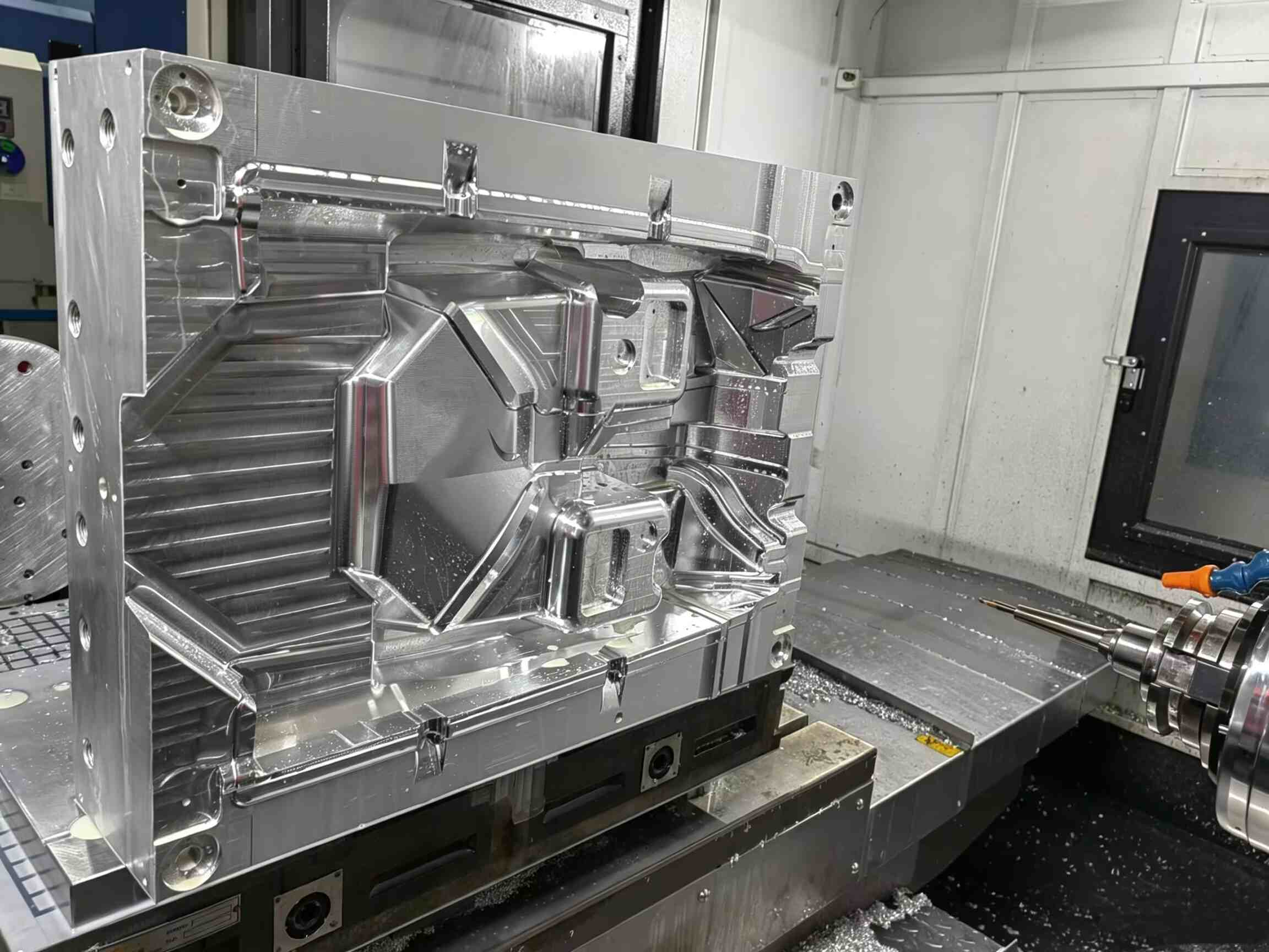
CNC-Fräsen & Drehen
5-Achs-CNC-Fräsen und -Drehen – Präzise 5-Achs-Fräs- und Drehbearbeitung für Prototypen und Serienfertigung von Metall- und Kunststoffbauteilen. Mehrseitenfräsen in einer Aufspannung kombiniert mit CNC-Drehen auf einer Plattform eliminiert den Teiletransfer zwischen Maschinen und ermöglicht eine Positioniergenauigkeit von ±0,01 mm ohne Toleranzanstieg zwischen den Aufspannungen. Umfassende CNC-Bearbeitung für Aluminium, Stahl, Edelstahl, Messing, POM, PEEK und technische Kunststoffe.
Erfahren Sie mehr
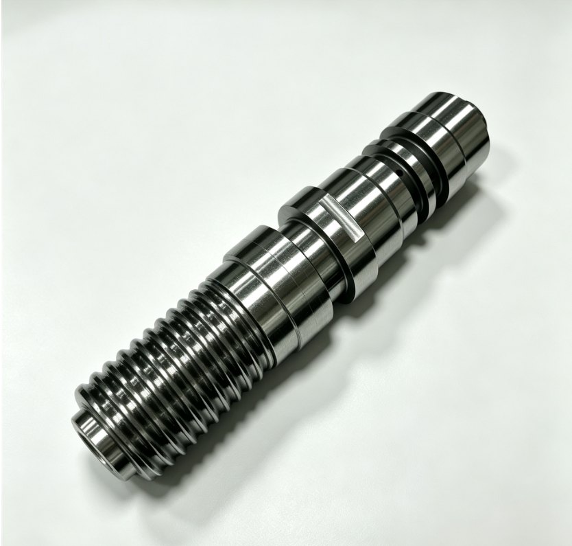
5-Achs-CNC-Bearbeitung
5-Achs-CNC-Bearbeitung – Simultane 5-Achs-Konturbearbeitung komplexer 3D-Oberflächen, Hinterschnittgeometrien und mehrseitiger Bauteile in einer einzigen Aufspannung. Eliminiert mehrfache Spannvorgänge und kumulative Toleranzfehler. Ideal für Laufräder, Turbinenschaufeln, orthopädische Implantate und 3D-Formhohlraumoberflächen im Spritzgussverfahren.
Erfahren Sie mehr
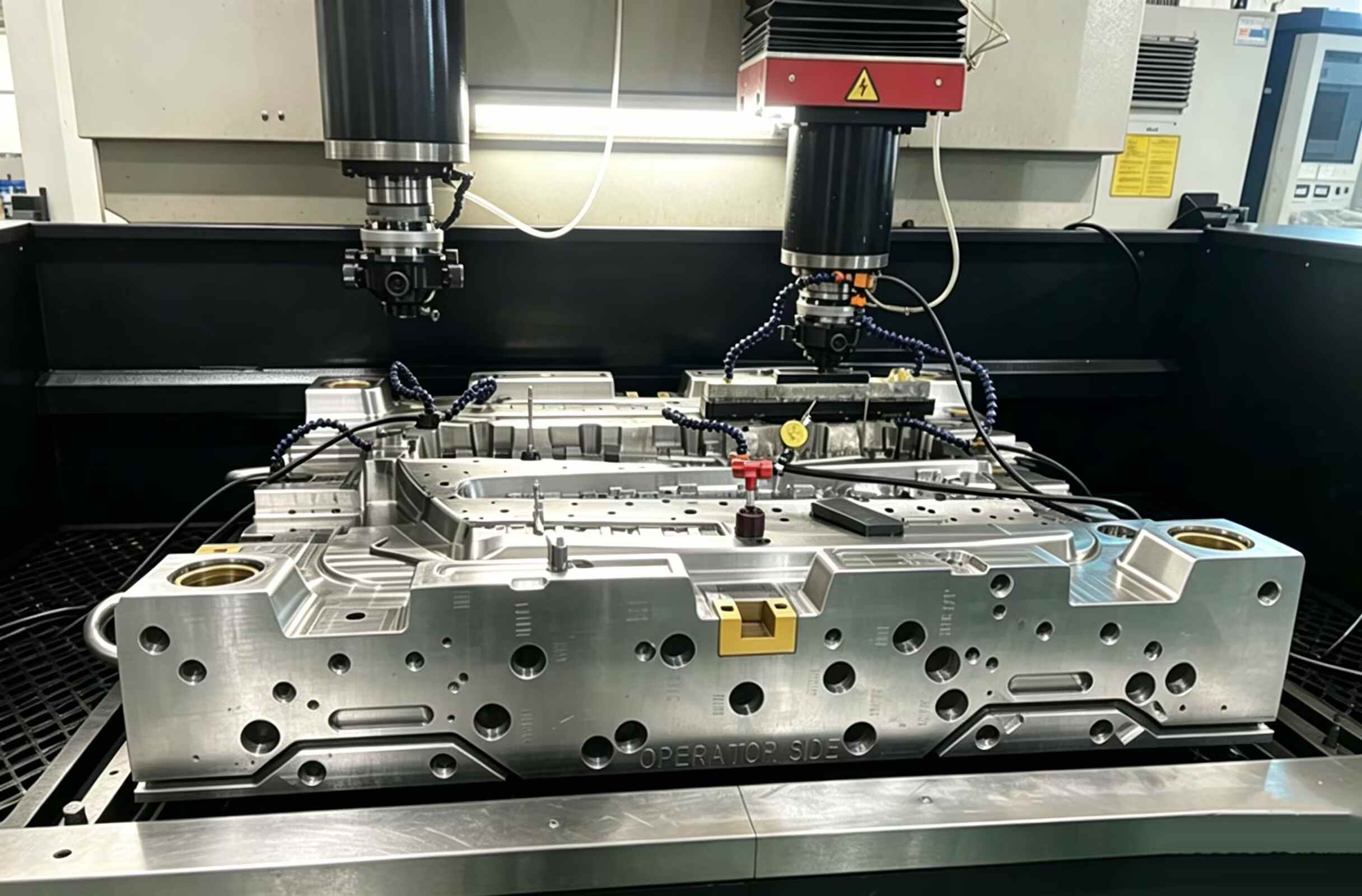
EDM-Funkenerosion
Funkenerosion – Präzisions-Senkerodierverfahren zur Bearbeitung von Hohlräumen in gehärtetem Werkzeugstahl mit scharfen Innenkanten, tiefen Rippen und komplexen 3D-Geometrien. Dabei werden speziell gefertigte Graphit- oder Kupferelektroden eingesetzt, um Bereiche zu bearbeiten, die mit rotierenden Schneidwerkzeugen nicht erreichbar sind. Kernverfahren für Spritzgussformen, Druckgusswerkzeuge und Sacklöcher mit einer Genauigkeit von ±0,005 mm.
Erfahren Sie mehr
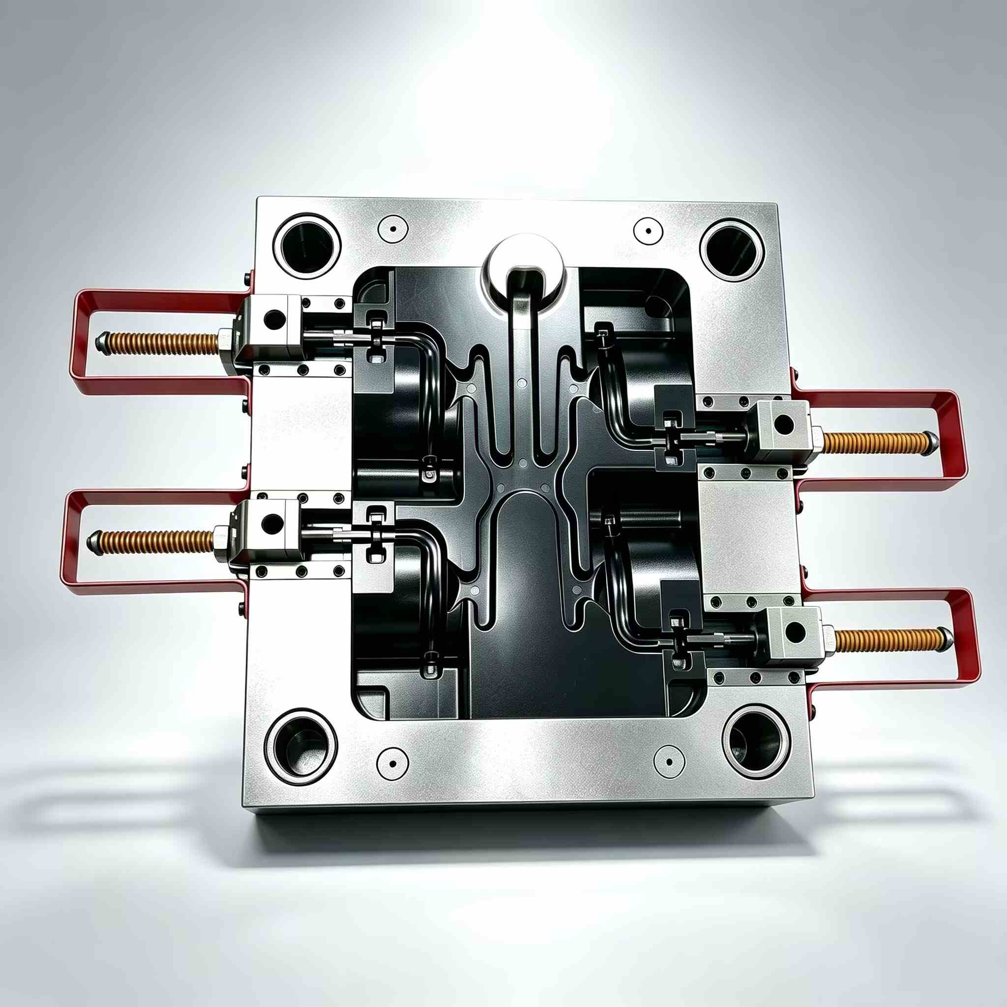
Zinkdruckgussform & Teile
Zinkdruckgussform – Präzisionswerkzeug für die Warmkammerfertigung von Zinklegierungsbauteilen mit hoher Fertigungsgeschwindigkeit. Konzipiert für die dünnwandige, endformnahe Produktion von Automobilverkleidungen, Elektronikgehäusen und Konsumgüterhardware mit Zykluszeiten von nur 3–5 Sekunden und gleichbleibender Oberflächenqualität im Gusszustand.
Erfahren Sie mehr
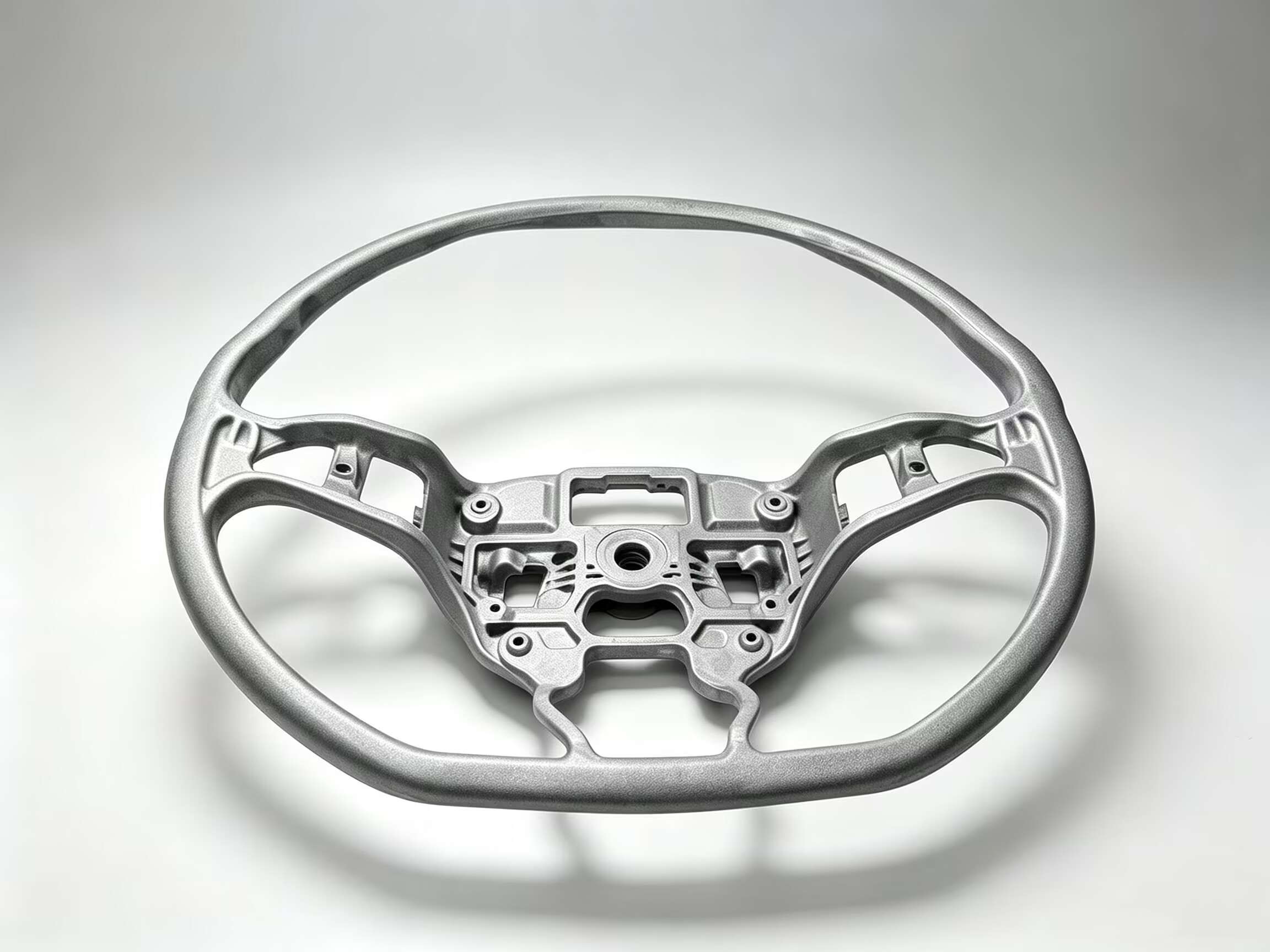
Magnesium-Druckgussformteile
Magnesium-Druckgussform – Kaltkammer-Hochdruckwerkzeug, entwickelt für die Magnesiumlegierungen AZ91D, AM60B und AS41B. Speziell für den Leichtbau in der Automobilindustrie, Gehäuse für die Luft- und Raumfahrt sowie tragbare Elektronik, wo jedes Gramm zählt. Ermöglicht die Herstellung von Bauteilen in Endform mit einem Gewicht von 1,8 g/cm³ – 33 % leichter als Aluminium und 75 % leichter als Stahl.
Erfahren Sie mehr
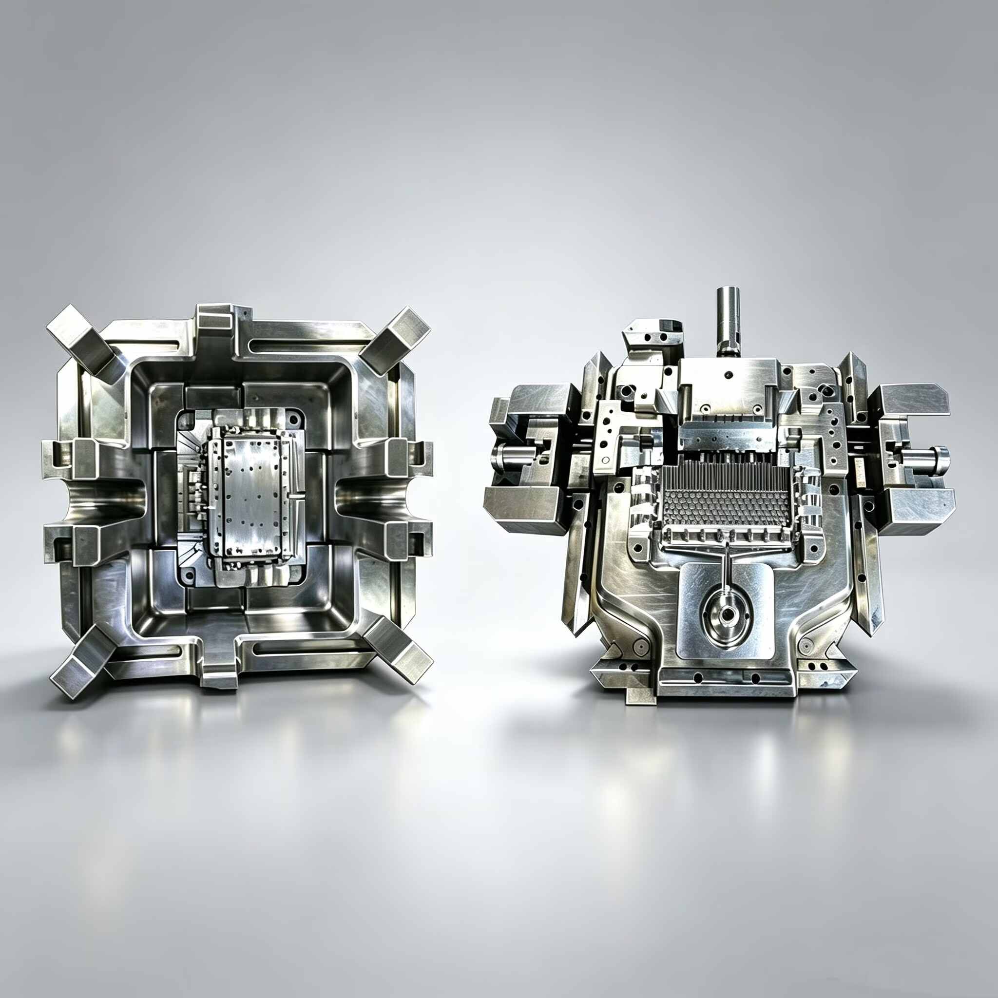
Aluminium-Druckgussform & Teile
Aluminium-Druckgussform – Kaltkammer-Hochdruckwerkzeug für die Legierungen A380, ADC12, A360 und AlSi10MnMg. Entwickelt für Antriebsstränge im Automobilbereich, Strukturbauteile für Fahrgestelle, LED-Beleuchtung und Gehäuse für Industrieanlagen. Standardmäßige Formlebensdauer: 300.000–500.000 Schüsse mit H13 ESR-Stahl, erweiterbar auf über 500.000 durch moderne PVD-Beschichtung und Vakuumwärmebehandlung.
Erfahren Sie mehr
Neueste Nachrichten
- 30th October 2026
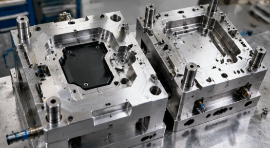
Low-Volume Injection Molding Cost: Complete 2026 Pricing & Tooling Breakdown
Low-volume injection molding gives you production-intent parts for design checks, pilot sales and bridge production. The budget covers the mold, part price and project services. This injection molding cost breakdown helps you review a quote.
How Do You Calculate Low-Volume Injection Molding Cost?
Use this equation: total project cost = tooling cost + (piece price x finished-part quantity) + project services. Services include DFM analysis, Moldflow, sampling, inspection, packaging, freight and engineering changes. The low volume injection molding price follows geometry, resin, cavity count, press size, cycle time and quantity.
What Does the Tooling Cost Include?
The low-volume injection molding tooling cost includes the mold base, steel, CNC machining, EDM, heat treatment, runners, cooling, ejection and trial molding. Sliders, lifters, threaded cores and inserts add fitting work. Ask the quote to list each item.
What Does the Part Price Include?
Your plastic injection molding cost per part follows resin and runner weight, scrap, machine time, labor, trimming, assembly, inspection and packing. The injection molding cost per unit falls as output rises. More cavities add balance and validation work. Ask for target cycle time and yield.
What Volume Fits a Low-Volume Injection Mold?
Volume describes the production plan, tool life and revision risk. A 500-part design check differs from a 20,000-part bridge run. Finished parts per run equal shots multiplied by cavity count, adjusted for samples and scrap. This matters when you compare prototype injection mold cost with bridge tooling cost.
Which Tooling Ranges Can You Use for Planning?
Directional 2026 ranges place a Class 105 aluminum tool around $2,000-$5,000+ and 500-10,000 shots. Class 103 P20 tooling runs around $5,000-$25,000+ and 100,000-500,000 shots. Class 101 hardened tooling can reach $50,000-$100,000+ and 1,000,000+ shots. Part size, steel, mold standard, finish and mechanism count set the quote. Compare aluminum injection mold cost and steel injection mold cost against tool life and forecast volume.
When Does a Bridge Tool Fit?
A bridge tool supplies parts for fit checks, customer samples or an early release. Aluminum can shorten machining time for limited shots. Record resin, gate, cooling and inspection data for the next tool.
Which Design Choices Change the Tool and Part Price?
Design choices set cost before machining. A rib, draft angle or parting-line change can remove a mechanism, shorten cooling or allow a smaller press. Connect each DFM change to a cost or risk.
How Do Undercuts and Tolerances Affect Cost?
Side holes, snap hooks, threads and inserts can require sliders, lifters, unscrewing cores or fixtures. Tight tolerances add EDM, grinding, fitting and inspection time. Mark seals, threads, datums and cosmetic zones on the drawing.
How Do Cooling, Gates and Ejection Affect Cycle Time?
Cooling often occupies 50%-80% of an injection cycle. Thick or uneven walls extend cycle time and machine use. Gates, runner balance and venting affect filling, weld lines and air traps. Ejectors and lifters affect release force and drag marks. Include these checks in DFM and Moldflow.
How Do Resin Choices Affect Cost?
Directional examples place PP at $1.50-$3.50/kg, ABS at $2.00-$4.50/kg and PC at $3.00-$6.50/kg. Grade, additives, drying, shrinkage and certification change price. Request the part-weight assumption and material lot record.
How Can You Compare Two Tooling Paths?
Use an injection mold cost calculator with the same assumptions for each supplier. List tooling, piece price, sampling, freight, scrap, maintenance and revisions separately. Late design review extends sampling.
What Is the Break-Even Quantity?
Use this formula: break-even quantity = (higher tooling cost – lower tooling cost) / (lower piece price – higher piece price). A $4,000 bridge tool at $2.40 per part totals $16,000 for 5,000 parts. An $18,000 production tool at $1.25 totals $24,250. Compare 1,000, 10,000 and 25,000 parts too.
Which Quote Details Should You Compare?
Compare steel, mold standard, cavities, shot life, runner, cycle time, sampling dates, inspection, packaging, freight, ownership and maintenance. Ask for steel-safe changes and a correction plan. These details show initial and later costs.
What Should You Request Before T1 Sampling?
Send the supplier 3D CAD, drawing, resin grade, color, part weight, projected area, forecast, first-release quantity, cosmetic zones, critical dimensions and delivery date.
What Should the T1 Sample Report Contain?
Request measurements, part weight, cycle time, resin lot, machine settings, defect photos, open issues and corrective actions. The process moves from product design and DFM to mold design, tooling, trials, pilot and mass production. Give each handoff an owner and release decision.
How Do You Check a Supplier’s Engineering Scope?
Ask who performs DFM analysis, Moldflow, mold design, machining, assembly, trials and low-volume injection molding support. Confirm the press, steel plan, inspection method and T1 sample date. Apply the same review to medical, electronics, automotive and industrial low-volume plastic parts.
How Can an Engineering-Led Supplier Control Low-Volume Cost?
Review how design feedback connects to tooling and sampling data. Check which engineering tasks happen before steel release and which records support the piece-price decision.
A Practical XINKEY MOULD Example
XINKEY MOULD describes 22 in-house designers, DFM and Moldflow, 19+ CNC centers and 90T-750T injection capacity. Its listed scope includes rapid prototype molds, low-volume trials, sliders, lifters, inserts, threading and 2K structures. Ask for the assigned engineer, DFM deliverable, press, T1 plan and inspection report. Review injection mold engineering solutions and custom plastic injection molds.
Review wall thickness, draft, steel, cycle time, cavity balance and release evidence. These details anchor a small batch injection molding cost review.
FAQ
Use these planning answers to frame a project-specific quote.
Q1: How Much Does a Low-Volume Injection Mold Cost in 2026?
A: A Class 105 aluminum tool often falls around $2,000-$5,000+, Class 103 P20 around $5,000-$25,000+, and Class 101 hardened tooling around $50,000-$100,000+. Geometry, cavities, finish and trial scope set the quote.
Q2: What Is the Cheapest Mold Material for a Small Batch?
A: Aluminum fits limited-shot validation. Choose by revision risk, resin wear, dimensions, shot plan and the next production step.
Q3: Does a Larger Cavity Count Lower the Cost per Part?
A: More cavities produce more parts per shot and can lower machine cost per part. They add runner balance, machining and cavity-specific inspection. Use break-even quantity to set the count.
Q4: How Does Cycle Time Affect Injection Molding Price?
A: Cooling, wall thickness, thermal balance and ejection set cycle time. Longer cycles use more press hours per order and raise piece price.
Q5: Can XINKEY MOULD Provide Low-Volume Injection Molding Support?
A: XINKEY MOULD lists rapid prototype molds, low-volume trials, DFM and Moldflow, precision sampling and support through mass production. Request the mold plan, press, T1 sample, inspection records and piece-price assumptions.
- 29th October 2026
What Is Considered Low-Volume Production? Batch Sizes, Quantities & Industry Benchmarks
What Counts as Low-Volume Production?
Low-volume production usually means about 10 to 10,000 parts in one planned run. Use that range to frame low-volume production quantities, then adjust it for industry, material, process, and qualification work. The same low-volume production volume can mean very different things in medical and consumer programs.
A Practical Quantity Range
Use these bands as planning references. They describe a product stage; applicable rules set legal and regulatory definitions.
Stage
Working quantity
Main purpose
Prototype
1 to 10
Form, fit, and early function
Low-volume production
10 to 10,000
Validation, launch supply, or specialized demand
Mass production
10,000 and above
Stable demand and dedicated capacity
The low-volume manufacturing batch size also depends on release timing. Five hundred units delivered once differs from five releases of 100. Forecast accuracy, storage, cash flow, and revision risk shape that choice.
Batch Size, Annual Volume, and Program Volume
Keep three figures on the purchase request: units per release, expected annual demand, and lifetime demand. A project may need 500 units for a first shipment and 2,000 across the year while the tool changes. That remains small-batch manufacturing with staged releases.
Which Industry Benchmarks Fit Your Batch Size?
Low-volume manufacturing benchmarks frame a quote and validation plan. Your forecast, regulatory plan, and supplier capacity review set the final range.
Planning Bands by Industry
Industry
Illustrative run
What sets the band
Medical and laboratory equipment
10 to 500
Traceability, qualification, and controlled design changes
Aerospace and defense components
10 to 1,000
Complex geometry and first-article work
Industrial equipment and automation
50 to 5,000
Project orders, replacement demand, and service parts
Automotive specialty and aftermarket parts
100 to 10,000
Platform life, tool life, and customer approval
Consumer electronics and smart hardware
500 to 10,000
Market pilots, cosmetic standards, and product revisions
Packaging and household products
1,000 to 10,000
Resin cost, cavity count, and unit economics
A 300-unit medical run can be a major validation build, while 5,000 electronics units can remain a market test. Product risk and approval work give quantity its meaning.
How Does Low-Volume Production Compare with Other Stages?
Purpose defines the stage. A prototype answers design questions, a pilot checks the process and work instructions, and a bridge run supplies customers while a higher-volume tool is completed.
Prototype, Pilot, and Bridge Production
Prototype parts can use a temporary process or substitute material. Pilot production uses the intended process, inspection method, packaging, and operator steps. Set the pilot production quantity from the test plan: 50 parts may cover an assembly study, while several thousand may support a launch build.
Bridge production carries approved material, drawing revision, and process settings into an early shipment. It gives you time to qualify a hardened tool or higher-cavity layout. Keep a clear record so the next tool uses those lessons.
When Mass Production Starts
Mass production starts when demand stays steady, revisions are controlled, quality data repeats, and unit economics support dedicated tooling. The threshold varies by product.
How Does Batch Size Affect Cost and Purchasing?
Batch size spreads fixed engineering and tooling costs across parts. It also sets inventory exposure and the number of design changes you can absorb.
Fixed Tooling and Unit Cost
Use this simple planning formula:
estimated unit cost = recurring part cost + (tooling and engineering cost / planned units)
Add freight, inspection, scrap, qualification, storage, and engineering changes when comparing quotes. These costs can outweigh a small piece-price difference.
The useful manufacturing quantity breakpoints for a quote may be 100, 500, 1,000, 5,000, and 10,000 units. Ask for each price at the same drawing revision, material grade, inspection scope, and delivery term.
Production Batch Size Planning
Production batch size planning starts with demand and ends with a release gate. Ask for minimum order, staged-release terms, tool ownership, cavity plan, shot count, packaging, and maintenance. A large order ties cash to a changing design; a very small order spreads tooling cost across too few parts.
When Does Low-Volume Injection Molding Fit?
Low-volume injection molding fits repeatable plastic parts in the hundreds or thousands when you need production-intent resin, stable cosmetics, and measured dimensions. Match tool structure to the forecast and design-change rate.
Tool Choice, Tool Life, and Cavity Count
Single-cavity or low-cavity tooling leaves room for early changes. Multi-cavity tooling lowers piece cost after geometry, resin, and assembly settle. Aluminum or soft steel suits an early run when tool life and resin conditions fit; hardened steel suits higher shot counts. Review tool life and cavity count against cycle time and demand.
Engineering Checks Before Steel Cutting
Start with DFM analysis. Check wall thickness, draft, parting line, shrinkage, undercuts, tolerances, cosmetic zones, and ejection. Uneven walls create sink or warpage; gate errors create flow marks, air traps, or weld lines.
Use Moldflow analysis for risks around gate position, runner balance, thin walls, cooling, or multi-cavity filling. Review sliders, lifters, inserts, threaded cores, mold strength, cooling, vents, and ejection before machining. T0 trials expose small details quickly.
What Should You Ask a Supplier Before Ordering?
The quote should end with records and owners. Price alone cannot show whether the batch will pass assembly or repeat across a longer run.
T1 Evidence and Quality Gate
Request T1 samples with resin lot, machine settings, mold temperature, pressure, cycle time, cavity ID, dimensions, cosmetic photos, and open actions. Set CTQs, part weight, flash and sink limits, and assembly tests before the run. Name the approver and correction date.
Procurement Questions
Ask for DFM timing, mold release, steel and heat-treatment details, T0 and T1 dates, correction rounds, pilot support, and the bridge production handoff. Compare two or three quotes against identical CAD data and material specifications.
When Should You Increase Production Volume?
Scale when the current tool, supplier, or release pattern reaches a measured limit. Consider a new tool when demand exceeds capacity, wear changes dimensions, cycle time misses the cost target, or a design freeze supports investment.
Carry the approved CAD revision, resin, Moldflow findings, T1 data, process window, and maintenance record into the next tool. This record anchors the next estimate.
Which Engineering Support Fits Your Low-Volume Production Plan?
Once the quantity plan reaches plastic tooling, XINKEY MOULD can connect the engineering handoffs in a low-volume injection molding run. The workflow covers DFM analysis, Moldflow analysis, mold structure, machining, cooling, venting, ejection, and trials.
Sliders, lifters, inserts, threaded cores, and runner systems can match the release size and change rate. T0 and T1 verification records the drawing revision, resin, and acceptance data for pilot or bridge production. Review the injection mold engineering solutions and custom plastic injection molds pages when requesting a quote. Include cavity count, steel, shot-life target, and T1 deliverables.
FAQ
Q1: What Is Considered Low-Volume Production?
A: A common planning range is 10 to 10,000 parts per run. Industry, process, material, and qualification work set the practical boundary.
Q2: How Do You Choose Low-Volume Production Quantities?
A: Combine the first-release need, annual forecast, validation plan, storage limit, revision risk, and supplier capacity.
Q3: Is 1,000 Units a Low-Volume Production Volume?
A: It can be. One thousand units may support a large medical validation program or an early consumer product launch.
Q4: What Should T1 Samples Include?
A: Request the resin lot, machine settings, cavity identification, dimensions, cosmetic photos, sample count, and open corrective actions.
Q5: When Does Low-Volume Injection Molding Make Sense?
A: It fits repeatable plastic parts in the hundreds or thousands when production-intent resin, dimensional control, and a path to bridge or higher-volume production matter.
For a project review, share the CAD file, resin, CTQs, first-release quantity, annual forecast, and target date. The quantity decision becomes much clearer when the tool plan and acceptance data sit in the same document.
- 29th October 2026
5 Common Reasons TPE Peels Off PC + ABS Electronic Housings — and the Mold Fixes
5 Common Reasons TPE Peels Off PC + ABS Electronic Housings — and the Mold Fixes
Why the bond fails at the interface, and which of those failures the tool can prevent
Dealing with a TPE overmold that lifts at the edge? Upload 3D CAD files for a DFM review and mold quote
A TPE grip can pass first article and still peel six months into the field. The failure rarely starts at the surface. It starts a few micrometres into the interface, where the bond either formed, half-formed, or never formed at all.
All five causes below look identical on a customer complaint: a lifted edge on a housing. They have different fixes, and only some of them belong to the mold. This article covers the five failure modes we see most often on PC + ABS electronic housings with a TPE-S or SEBS overmold, what each one looks like in a peel test, and the tool-side changes that remove it before steel is cut.
Why Is PC + ABS a Difficult Substrate for TPE?
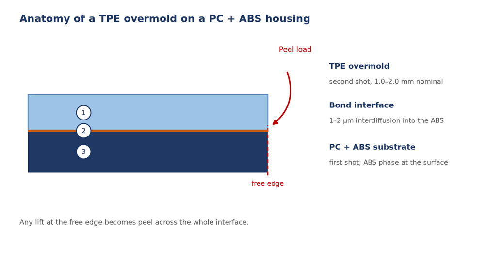
PC + ABS is a blend, not a single polymer. The ABS phase gives the surface enough chemical affinity for a TPE-S overmold to diffuse into it. The PC phase does not. Bond strength therefore depends on how much ABS sits at the surface where the second shot lands, and that fraction shifts with grade, flow history, and colour.
The second difficulty is thermal. PC + ABS needs a hot barrel and a hot tool. TPE-S needs a much lower melt temperature. The window in which the TPE arrives hot enough to diffuse into the substrate, but not so hot that it degrades the ABS phase, is narrow. Most of the five failures below are different ways of falling out of that window.
Figure 1. The bond is a 1–2 µm interdiffusion layer, not a glued surface. Load at the free edge stresses the whole interface.
The Five Failure Modes at a Glance
Failure mode
What you see
What actually happened
Primary owner
1. Interfacial contamination
Clean lift, glossy TPE underside
No bond formed
Process + tool
2. Cold interface
Low peel strength, no visible defect
No interdiffusion
Tool + process
3. Cold weld line
Peel starts at one point, then runs
Two fronts met and lost heat
Tool
4. Sharp edge or thin wall
Lift begins at the TPE boundary
Stress concentration at the edge
Tool
5. No mechanical interlock
Passes the peel test, fails in use
Adhesion carrying peel load
Tool + design
Figure 2. Five different weak points, one identical symptom.
Reason 1: The Bonding Surface Was Contaminated
What it looks like. The TPE lifts as a clean sheet. The underside is glossy, and the substrate shows no trace of polymer pulled away. That detail tells you which failure you have. A cohesive failure, where material tears on one side, means the bond was stronger than the material. An adhesive failure, with a clean interface, means there was no bond to break.
Why it happens. Mold release agent from the first shot, silicone from an adjacent process, cutting oil, dust from storage, or skin oil from manual insert loading all sit between the two melts. Gas does the same thing. An unvented first-shot cavity leaves a deposit in the bonding area that behaves like a release film. So does a hot insert that has been sitting and outgassing.
Mold fix. Remove external release agent from the first-shot tool and rely on draft and ejection instead. Vent the first-shot cavity at the last-fill point so gas leaves rather than plating out on the bonding surface. Keep ejector pins and lubrication points out of the bond area. Then write the handling rule into the work instruction: gloves, no stacking of freshly molded inserts, and a maximum dwell time before the second shot.
Reason 2: The Substrate Was Too Cold When the TPE Arrived
What it looks like. Peel strength is low, but the failure does not look contaminated. Under a microscope the interface shows little or no interdiffusion. The TPE sat on the surface instead of dissolving into it.
Why it happens. Bonding between TPE-S and the ABS phase is diffusion, and diffusion needs the substrate surface above its softening range. A first-shot insert that cools on a tray, a rotary tool whose second station runs colder than the first, or a thick metal insert acting as a heat sink will all drop the surface below that range before the TPE arrives.
Mold fix. Control the second station independently: separate temperature zones on the core and cavity side, and a controlled insert pocket instead of a bare steel seat. Where the geometry allows, insulate the insert seat to slow heat loss. Size the runner and gate so the melt reaches the bonding area hot, and confirm it in the flow simulation by reading melt temperature at the interface, not just at the gate.
Reason 3: A Cold Weld Line Formed in the Bond Area
What it looks like. Peel starts at one point and then runs along the boundary. The starting point is usually opposite the gate, behind a boss, or between two pins. A visible line often crosses the TPE at the same spot.
Why it happens. Any core, boss, hole, or rib in the TPE cavity splits the flow. When the streams rejoin, both fronts have already lost heat and picked up air. Two cold fronts meeting form a weld line with weak bonding to the substrate, and if the gas has nowhere to go, a burn or a short shot at the same location.
Mold fix. Move the gate so the flow front reaches the bonding area as a single front. Add vents at the last-fill point, and overflows where venting is not possible. Use the flow simulation to plot weld-line position and air traps on top of the bonding area. If a weld line lands inside it, change the gate before cutting steel.
Reason 4: The Edge Geometry Starts the Peel
Figure 3. A feather edge concentrates load at a single point. A dovetail moves that load into the geometry.
What it looks like. The lift begins at the boundary between TPE and exposed substrate, usually within the first few millimetres. The bond area itself is intact, which is why a peel test cut from the middle of the part can pass while the housing still fails in the field.
Why it happens. A sharp step, or a feather edge thinner than about 0.5 mm, is a stress concentrator. Under any peel or thermal load the stress at the tip is many times the nominal value, so a bond that is strong enough in the middle fails at the edge. Thin TPE sections make it worse. Below roughly 1 mm the melt loses heat quickly, packing is poor, and the bond at the edge becomes the weakest in the part.
Mold fix. Radius the transition and hold the TPE section at a thickness the material can fill and pack. 1.0 to 2.0 mm is a workable starting range, confirmed against the flow simulation. Where the design allows, move the parting line away from the sealing edge so flash or mismatch does not sit on the boundary that starts the peel.
Reason 5: Adhesion Is Carrying Load It Was Never Designed to Carry
What it looks like. The part passes the peel test and fails in use. After drop, after thermal cycling, after a screw boss is tightened, or after cleaning with a solvent.
Why it happens. TPE expands several times more than PC + ABS over the same temperature range. Every thermal cycle puts the interface in shear, and every assembly step adds a peel component at the edge. Adhesion alone has no answer to repeated shear. A mechanical lock does.
Mold fix. Build the interlock into the tool: through-holes the TPE fills, dovetail or T-slot grooves, undercuts on the substrate, or a tongue-and-groove at the boundary. These are mold features, not material changes, and they are only free if they were designed in. The rule is simple. The bond seals, and the geometry holds.
What the Mold Can Fix, and What the Process Still Owns
Buyers often ask for a tooling change to solve a process problem. The table below separates the two, so the fix lands on the right side of the purchase order.
Failure mode
Tool-side action
Still required in production
1. Interfacial contamination
Vent the first-shot cavity at last fill; keep ejectors and grease points out of the bond area
Clean inserts, gloves, no external release agent
2. Cold interface
Independent second-station temperature zone; controlled insert pocket
Transfer time, insert preheat, machine settings
3. Cold weld line
Gate position, vent and overflow layout
Verified shot parameters, regrind control
4. Sharp edge
Radius, wall thickness, parting-line placement
Fill and pack profile confirmed on the press
5. No interlock
Through-holes, dovetails, undercuts
Assembly and handling designed not to peel the edge
Figure 4. Gate, vent, per-station temperature and interlock: all decided before steel cutting.
XINKEY MOULD reviews these five modes as part of DFM, before tooling starts. That covers wall and edge geometry, gate and vent layout, per-station temperature zoning, and interlock features for TPE overmolds. Capability covers ±0.01 mm-level CNC machining, injection presses from 90T to 750T, and 2K tooling on a rotary table. Those figures describe company capability, not measured results for any specific housing.
How Should You Validate the Fix Before Mass Production?
A peel test that only reports force will hide the difference between the five modes. Record the failure type as well: adhesive, cohesive, or mixed. A cohesive break at high force is a good bond. A mixed break at the edge points to geometry. An adhesive break at low force points to contamination or a cold interface.
Run the test on parts from the first 100 shots, then repeat it after a thermal cycle. Section the edge and look at the interface under a microscope, where the interdiffusion layer is visible or it is not. Then repeat the peel after assembly and after cleaning with the solvent your customer will actually use.
Buyer Checklist for a TPE Overmold Project
Both resin grades, including the ABS fraction and any flame retardant in the PC + ABS
The TPE grade and hardness, and whether the bond is adhesion-only or mechanically locked
3D model and 2D drawing with the TPE wall thickness and edge geometry called out
Cosmetic and sealing requirements at the TPE boundary
Annual volume, expected mold life, and cavity target
Peel acceptance criteria: force, failure mode, and test method
Cleaning solvents and assembly loads the housing will see in service
FAQ
Why does TPE peel off PC + ABS but bond well to PP?
Polypropylene and TPE-S are both olefinic, so the interface diffuses easily. PC + ABS is a blend. Only the ABS phase is compatible with TPE-S, and the PC phase is not. Bond strength therefore depends on the ABS fraction at the surface, which is why two suppliers’ PC + ABS can behave differently in the same tool.
Can changing the TPE grade fix peeling?
Sometimes. A grade formulated for polar substrates will bond better to the ABS phase than a general-purpose grade. But if the failure is contamination, a cold interface, a weld line, or a sharp edge, a new grade only moves the failure point. Diagnose the mode first, then change material.
Does plasma or flame treatment help?
Both raise surface energy and improve wetting, and both are used in production. They also add a process step that has to be controlled and monitored, and they do not fix a weld line or a stress concentration. Treat them as a complement to tool geometry, not a replacement.
How thick should the TPE be?
Thick enough to fill and pack, thin enough to stay flexible. 1.0 to 2.0 mm covers most grips and seals. Below about 0.5 mm at the edge, the material cools before it can bond, and the edge becomes the peel initiation point.
Can peeling be fixed in an existing mold?
Partly. Gate position, venting, and temperature zoning can often be changed. Adding an interlock or a radius usually means cutting new steel, and sometimes a new insert. That is why the five modes are worth reviewing during DFM, before the first cut.
Request a DFM Review and Quote
Have a TPE overmold that lifts at the edge, or a housing about to go into tooling? Upload your 3D CAD files, both resin grades, annual volume, and the cleaning and assembly conditions the part will see through the Free Quote page. The service page accepts STEP, STP, IGES, IGS, XT, DWG, PDF, and ZIP files up to 30 MB. For direct contact, use the Contact Us page or email Contact-Xinkey@xinkeymould.com.
- 23rd October 2026
Low-Volume Injection Molding: On-Demand Production & Fast Tooling
Why does Low-Volume Injection Molding Fit Uncertain Demand?
Low-volume injection molding gives you a production path when demand moves. You can make saleable parts, validate a design, and learn from field use before committing to a large steel tool.
On-demand production lets you buy smaller releases, keeping cash and warehouse space tied to real orders. Aluminum tooling can bridge a prototype and stable production. The choice depends on geometry, resin, quantity, and change cost.
When does On-Demand Production Make Sense?
Use it for a new product with uncertain demand, irregular replacement orders, or planned design revisions. It suits medical, laboratory, smart hardware, and industrial products that need hundreds or a few thousand validated parts. The run can expose fit, assembly, and surface issues while tool changes remain manageable.
What does Fast Tooling Change?
Fast tooling compresses the time between a frozen CAD file and useful parts. A practical route combines a rapid tooling review, mold design, CNC machining, trial molding, and a T1 check. The goal is a controlled learning cycle. Aluminum tooling can suit early production and provide data for a later hardened mold.
How does the Process Control Tooling and Production Risk?
Low-volume injection molding production still needs production-grade thinking. A short run can hide a poor gate or unstable cooling layout, then repeat the problem as demand rises. Review the part, mold, and press together so each decision has a measurable reason.
What Happens in an Injection Molding DFM Review?
An injection molding DFM review checks wall thickness, draft, parting line, gate, venting, ejection, shrinkage, and press tonnage. Mold-flow simulation can show filling balance, air traps, weld lines, and cooling differences before steel is cut. This mold design for manufacturability step also flags undercuts that may need sliders, lifters, or inserts. Marked-up CAD views show the cost and schedule effect of each change.
How are Tooling and Samples Verified?
After machining, trial molding checks the cavity, runner, cooling, and ejection systems. Record T0 findings, correct root causes, and review T1 parts against the drawing. Ask for the inspection method, resin lot, and sample process conditions.
Which Quality Features Need a CTQ Plan?
Mark CTQ features where a dimensional shift affects sealing, fit, force, optics, or electrical safety. Link each CTQ to a gauge or CMM check, sampling frequency, and limit. This keeps a low-volume trial run useful for repeat orders and gives evidence beyond a visual sample.
Which Part Design Choices Affect Cost and Speed?
Part geometry sets much of your tooling cost before a purchase order. Design edits can shorten injection molding lead time, reduce secondary work, and simplify plastic injection mold maintenance.
How Much Draft Angle Do You Need?
Add a draft angle to faces that pull along the opening direction. Textured faces and deep ribs usually need more draft than smooth faces. Review the parting line with the ejection plan so the part stays on the moving side and leaves the cavity cleanly. This small check prevents drag marks, whitening, and stuck parts during sampling.
Why does Wall Thickness Matter?
Keep wall thickness as even as the function allows. A common starting range for many thermoplastics is about 1 to 3.5 mm, followed by a resin-specific review. Thick zones cool slowly and can create sink marks; thin zones can restrict filling. Use ribs, bosses, and gussets that support the part while keeping section mass compatible with the cooling cycle.
Where do Radii and Vents Help?
Use internal radii at corners to lower stress and match the cutting path of an end mill. Put vents near the end of melt flow so trapped air can leave. Good venting supports filling and reduces burn marks.
How should You Specify Surface Finish?
Choose the finish that matches function and viewing distance. A polished cavity adds hand work and schedule. A machined or light-texture finish may meet the requirement with a simpler tool. State the finish by area.
How should You Plan Quantity, Materials, and Tool Life?
Quantity planning connects your forecast to mold structure. Review the next 12 to 24 months, order pattern, and finished-goods cost before choosing cavity count or steel grade.
Is a Single-Cavity or Multi-Cavity Mold Better?
A single-cavity mold keeps early tooling and change work easier to control. A multi-cavity mold can lower the piece price when demand is steady, provided geometry and runner balance support even filling.
Family molds can combine related parts for a pilot production run, but each cavity needs its own inspection limits. Ask for a cycle-time and capacity comparison, then select cavities with demand in view.
Which Material Fits a Bridge Production Run?
Select resin by strength, heat, chemicals, color, and regulatory need. PP, ABS, PC, PA, POM, and filled grades differ in shrinkage and cooling. Share the final material early so gate, vent, cooling, and steel decisions match it.
When should You Move to a Hardened Tool?
Move when demand, wear, or dimensional stability justifies the capital. Aluminum tooling can carry early on-demand production and design learning. A hardened steel mold fits a repeat program with higher shot counts, tighter process windows, or long service expectations. Keep the CAD, inspection data, and approved process settings from the first tool so the next tool starts with evidence.
What should You Ask a Supplier Before Ordering?
Your supplier conversation should end with numbers, documents, and named owners. The checklist below helps you compare a quote by total project risk and tooling cost.
Which Questions Clarify the Real Schedule?
Ask for DFM timing, tool build days, first trial date, correction allowance, sample quantity, and the expected injection molding lead time. Confirm who approves material substitutions and how an engineering change affects the quote. A supplier that supports low-volume trial production should also explain how it will scale to small-batch production or bridge production after approval.
Which Records Support a Purchase Decision?
Request the DFM report, mold-flow findings when used, steel and heat-treatment records, CTQ dimensional reports, and the T1/T2 issue list. Ask how cooling, venting, ejection, and wear parts will be checked. These records support tool release.
Where Can Engineering Support Shorten the Route to Production?
For projects that need both rapid tooling and a low-volume injection molding production plan, XINKEY MOULD works from the product-design stage through DFM, mold design, machining, trial molding, and small-batch production. Its engineering workflow covers wall thickness, draft angle, gate and runner balance, flow analysis, cooling, venting, and ejection before tooling starts.
The team also handles sliders, lifters, inserts, threaded cores, and two-shot structures when the part needs them. Multi-stage machining checks and trial-molding verification create a traceable handoff into pilot production. If you need to compare a rapid prototype mold with a production-ready plastic injection mold, share the CAD file, resin, CTQ features, expected quantity, and target date so the quote reflects the actual decision.
FAQ
Q1: What is low-volume injection molding used for?
A: It produces saleable parts for design validation, market testing, replacement demand, and early production before a larger tooling investment.
Q2: How does aluminum tooling affect fast tooling?
A: Aluminum tooling supports quick machining and practical revisions for early runs. Tool life and resin choice still need a project-specific review.
Q3: What information should you send for an injection molding DFM review?
A: Send the 3D CAD file, 2D drawing, resin and color, annual and first-run quantity, CTQ dimensions, finish callouts, and target date.
Q4: How long is the injection molding lead time?
A: It depends on geometry, mold structure, material, inspection needs, and revision rounds. Ask for separate dates for DFM, tool completion, T1 samples, corrections, and shipment.
Q5: When does a multi-cavity mold make sense?
A: It fits steady demand where balanced filling and shared inspection controls can lower the part cost. A single-cavity tool often suits early learning and changing designs.
- 22nd October 2026
5 Benefits Of Rapid Tooling For Automotive Injection Molding
Car projects frequently shift. This usually happens once an initial physical part goes into a dashboard, console, lamp housing, or battery assembly. Rapid tooling for automotive injection molding offers a quick, manageable route. It takes you directly from CAD data to working parts.
These tools might rely on aluminum or soft steel. The exact metal depends on your target volume and chosen resin. The goal remains highly practical. You get to evaluate the piece and process. Plus, you can verify purchasing choices before paying for an expensive, long-lasting production tool.
What Is Rapid Tooling for Automotive Injection Molding?
It acts as a distinct mold-creation method. It fits automotive prototype production and medium-batch runs perfectly. A basic mold utilizes fewer cavities. It also features a very standard ejection setup.
Conversely, standard production molds require tough hardened steel. They need intricate slides, lifters, and balanced runners. Your final choice relies heavily on volume, geometry, resin, visual requirements, and strict delivery deadlines.
1. Faster Structural Changes Before Steel Commitment
The first physical sample exposes decisions that a screen can hide: a rib may interfere with a connector, a draft angle may hold the part on the wrong side, or a gate mark may land on a visible surface. A rapid prototype mold gives your design team a short feedback loop. You can review T1 samples, record the change, and update the part or mold while the project is still flexible.
How Does the Review Work?
Ask for DFM analysis before machining begins. The review should cover wall thickness, draft, parting line, undercuts, ejection, shrinkage, and the intended press.
The engineering record should also show which change affects tool cost, cycle time, or assembly fit. This makes a quote useful for purchasing because you can compare the cost of a revision with the cost of carrying a risky feature into production.
2. Earlier Validation of Automotive Plastic Parts
Automotive rapid injection molding lets you test structural features with a real molded part. Deep cavities, thin walls, ribs, bosses, and snap fits behave differently under filling, packing, cooling, and ejection. A digital model can guide the review, yet a physical sample still needs fit checks, load checks, surface review, and dimensional measurement.
Where Does Mold Flow Analysis Help?
Mold flow analysis maps gate position, runner balance, filling pattern, weld lines, air traps, shrinkage, and warpage and sink marks before steel is cut. The result is a mold design validation record that points to a specific action, such as moving a gate, changing a rib, adding a vent, or adjusting a cooling circuit.
For complex mold structures, this early work reduces the chance of discovering a slider, lifter, or insert problem during a late trial.
3. Better Control of Prototype Spending
Prototype tooling turns a large tooling decision into staged purchasing. You can order a defined quantity for fit, durability, and user testing, then decide whether the geometry merits a production tool. This fits projects that need low-volume injection molding for a pilot build, a customer trial, or a limited vehicle release.
What Should Purchasing Compare?
Compare the tool price with revision cost, resin usage, inspection time, machine size, and the value of the parts being tested. Ask whether the tool can be modified, whether wear parts are replaceable, and which dimensions will be measured on each sample.
A low entry price loses its value when the tool cannot support the next test or when every change requires a new build. A clear inspection plan also helps engineering, quality, and purchasing agree on the release decision.
4. Shorter Lead Times for Testing and Launch Decisions
Rapid tooling for automotive parts can move first shots into a working press in days or a few weeks, depending on geometry, material, and tool construction. CNC-machined aluminum or soft tooling often suits an early run. The supplier still needs time for design review, machining, assembly, trial molding, and corrections, so a realistic schedule matters more than a headline number.
Which Process Details Affect the Schedule?
Injection molding cycle time depends heavily on wall thickness, resin, mold temperature, and cooling layout. Well-planned mold cooling channels remove heat from thick areas and reduce the wait before ejection. Venting, runner balance, and a stable ejection system also affect the number of trial loops. When you request a quote, ask for milestones for DFM approval, steel release, first trial, dimensional report, and sample shipment.
5. A More Practical Mass Production Transition
Rapid tooling can use production-grade plastics, so the samples can represent the mechanical behavior, appearance, and assembly feel expected from the final part. The tool itself may have a shorter service life than a hardened production mold. That distinction should be written into the sourcing plan.
How Do You Plan the Handover?
Carry the approved CAD revision, resin grade, shrinkage data, gate location, cooling notes, and inspection results into the automotive injection molding tooling package.
A multi-cavity mold may need a new runner balance study and a different press condition. Treat the prototype run as process learning: record fill time, packing, cooling, ejection, and key dimensions. Those records shorten the mass production transition and give the production team a starting process window.
What Should You Look for in a Rapid Tooling Partner?
The practical value of a rapid tool comes from decisions made before cutting steel. XINKEY MOULD uses an engineering-first workflow that starts with DFM analysis and mold flow analysis, then moves through mold design, precision machining, trial molding, and verification.
Its team includes 22 in-house designers, with support for rapid T1 samples, low-volume injection molding, sliders, lifters, inserts, hot or cold runners, and cooling-system design. The automotive workflow includes an IATF-aligned process and PPAP documentation available on request.
For buyers comparing suppliers, the useful question is whether the same team can carry approved changes into production tooling. Its injection mold engineering solutions cover that design-to-sampling handoff and keep the release record tied to the mold revision.
FAQ
Q1: What is rapid tooling for automotive injection molding used for?
A: It produces early automotive plastic parts for fit checks, functional tests, pilot builds, and market or customer review before a long-life production mold is released.
Q2: When should you request DFM analysis?
A: Request DFM analysis before steel machining. Review wall thickness, draft, parting line, gates, ejection, cooling, shrinkage, and press requirements while design changes remain manageable.
Q3: Can rapid tooling support PPAP documentation?
A: The supplier can prepare PPAP documentation when the project quality plan calls for it. Confirm the required records, dimensional reports, material certificates, and process data before the first trial.
Q4: How fast can a rapid prototype mold deliver T1 samples?
A: A simple tool may reach T1 samples in days or a few weeks. Geometry, resin, tool material, cavity count, and the number of trial corrections set the actual schedule.
Q5: Does rapid tooling replace a production mold?
A: It supports prototype and bridge quantities. A hardened production mold is usually required for high shot counts, multi-cavity output, tight process control, and long service life.
- 15th October 2026
5 Strategic Benefits of Outsourcing Rapid Tooling
A launch date can slip long before the first molded part. The delay often starts with a wall thickness that traps heat, a weak draft angle, or a late gate decision. Outsourcing rapid tooling puts engineering, machining, trial molding, and measured samples on one project path.
A capable tooling supplier connects speed with part quality and a credible route to production through rapid tooling services.
Benefit 1, Shorten Your Time to Market
Rapid tooling compresses the work between a released CAD file and a tested molded part. Engineering review, material planning, mold design, and machine scheduling can start from the same controlled data set.
Run Design and Manufacturing Work in Parallel
An outside team can review draft, wall thickness, undercuts, parting lines, gate position, ejection, and cooling while your product team closes cosmetic details. That overlap may remove several handoffs. It also gives procurement one schedule covering tool design, machining, assembly, trial, inspection, and sample shipment.
Set a Clear Sample Milestone
Ask the supplier to quote a date for T1 samples and list the inputs that control it. Standard tools may reach T1 in two to four weeks. Unscrewing or two-material tools can take four to eight weeks. Complexity, steel choice, bought-in components, and CAD changes still affect time to market.
Benefit 2, Turn Tooling Cost into a Controlled Project Budget
Internal tooling requires design hours, CNC and EDM capacity, assembly skill, press time, metrology, and corrections. Outsourcing places those items inside a defined project scope for comparison against launch volume.
Compare the Full Cost of Ownership
Compare quotations by total project cost. Repeated sampling, steel welding, long cycles, and early wear all add expense. Ask each tooling supplier to state the mold steel, expected life, cavity count, runner type, replaceable wear parts, inspection scope, trial rounds, and change policy.
Match the Tool to Expected Volume
A rapid prototype mold can use a simpler layout and steel suited to design validation or an early market run. A production tool needs balanced cooling, durable sliding parts, controlled hardness, and maintenance access. Share annual volume and likely product revisions before the quote.
Benefit 3, Find Design Risks Before Steel Is Cut
Small CAD choices can create large tool changes. Thin ribs may fill poorly, thick bosses can sink, limited draft can mark the surface, and an undercut may require a slider or lifter. Early engineering review gives you time to change the part file while the change is still simple.
Review the Part through DFM
A useful DFM analysis marks wall thickness, draft, shutoffs, parting lines, ejection points, tolerances, surface requirements, and assembly interfaces. It should also explain why each item matters.
For example, keeping a concentric bore on one mold half reduces mold-shift and tolerance-stack risk. A purchasing team can then approve the tool scope with visible technical reasons.
Test Flow, Cooling, and Warpage Digitally
Mold flow analysis can compare gate positions, pressure, weld lines, air traps, shrinkage, cooling, and warpage before machining. Moving a gate 5 mm in a simulation is a short task. A change after steel cutting can require welding, machining, polishing, and another trial.
Benefit 4, Validate Materials with Production-Like Parts
A printed prototype answers fit and appearance questions. It rarely reproduces resin flow, fiber orientation, shrinkage, weld lines, sink, or ejection behavior from molding. Rapid injection molding gives you parts made with the intended resin and a process close to the planned production method.
Test the Resin in the Intended Process
Use molded samples to compare candidate resins for stiffness, impact, heat, chemical exposure, sealing, color, and surface finish. Process details matter. Phenolic materials, for example, require controlled mold heat and effective venting. Insert-molded parts need secure insert location under injection pressure. Two-material parts need a sound bonding interface and accurate tool alignment.
Use Measured Samples for Decisions
Define the sample plan before the tool trial. Record resin grade, drying condition, melt and mold temperatures, pressure, cycle time, and cavity number. Then inspect critical dimensions and run the product tests that decide release.
A nice-looking sample can still hide a weak process window. Measured evidence gives engineering and purchasing the same basis for approval.
Benefit 5, Create a Practical Bridge to Mass Production
The first acceptable shot proves that the tool can make a part. Pilot runs test repeatability across cavities, shifts, and material lots. Outsourcing rapid tooling delivers the planned value when one team carries the project through sampling and early production.
Stabilize the Process during Pilot Runs
Low-volume production and bridge production let you supply launch units while the team checks cycle time, scrap, dimensional drift, assembly fit, packaging, and maintenance needs. Engineers can tune cooling, venting, packing, and ejection with direct access to the tool. That continuity matters when a defect appears only after a longer run.
Protect Return on Tooling Investment
Earlier sales help recover the tool investment, though repeatable output drives the larger return. Review yield, labor content, resin use, cycle time, press tonnage, and wear-part access. A parting-line choice that lowers projected area may allow a smaller press. A hot runner may cut runner waste at high volume. Each decision should connect to your forecast and unit-cost target.
What Should You Expect from an Engineering-Led Tooling Partner?
The five benefits depend on one connected engineering record from DFM through trial molding. XINKEY MOULD assigns 22 in-house designers to product review, mold design, and mold flow analysis. Its documented process covers wall thickness, draft, parting lines, sliders, lifters, cooling, venting, ejection, and material selection before machining. High-precision CNC work reaches ±0.01 mm-level control, and molding equipment spans 90T to 750T for sampling and production handoff.
For a buyer, the useful point is continuity. The same project can move from a 24-hour DFM report to tooling, T1 inspection, pilot quantities, and injection mold manufacturing. That structure makes design changes, sample findings, and production settings easier to trace. You can request a project review with the CAD file, resin, annual volume, finish, tolerance, and target sample date.
FAQ
Q1: When Should You Outsource Rapid Tooling?
A: Outsource when your launch plan needs molded parts sooner than your internal engineering, machining, or press capacity allows. It also suits projects that need DFM, material trials, or a direct path into pilot production.
Q2: What Files Should You Send for a Rapid Tooling Quote?
A: Send a 3D CAD file, a dimensioned drawing, resin grade, surface requirements, critical tolerances, annual volume, target tool life, and the required T1 date. Add assembly data when mating parts control fit.
Q3: How Can You Compare Tooling Quotes Fairly?
A: Compare steel, cavities, runner system, mold standard, expected life, inspection scope, trial rounds, sample quantity, change terms, lead time, and shipping. A line-by-line comparison reveals what each price includes.
Q4: Can Rapid Tooling Use Production Resin?
A: Yes. A suitable mold can run production resin for functional, dimensional, and assembly tests. Confirm drying, processing temperature, shrinkage allowance, and any fiber or flame-retardant content before tool design.
Q5: Can a Rapid Tool Move into Mass Production?
A: Some tools can support continued production when their steel, cooling, cavity layout, wear parts, and press interface match the volume target. Ask the supplier to state the expected shot life and maintenance plan in the quote.
Unser Service

Projekt-Engineering & DFM
Wir nehmen Ihre Datei nicht einfach entgegen und legen sofort los. Bevor auch nur ein einziger Stahl bearbeitet wird, prüfen unsere Ingenieure Ihre Konstruktion, um potenzielle Kostenfaktoren frühzeitig zu erkennen. Von der ersten Kontaktaufnahme bis zur Auslieferung betreut ein fester Ingenieur Ihr Projekt.
Erfahren Sie mehr
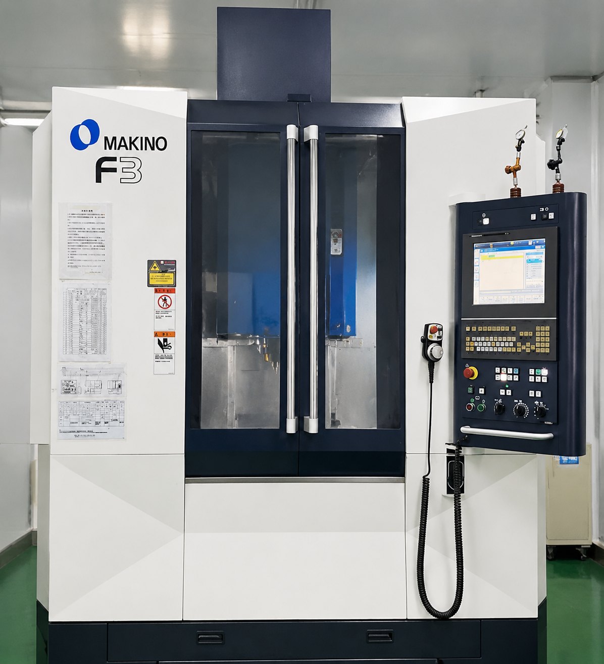
Präzisionsformenbearbeitung
→ CNC-Bearbeitung (±0,005 mm)
→ EDM – komplexe Kavitäten, die andere Verfahren nicht bearbeiten können
→ Drahterodieren – filigrane Profile, verzugsfrei
Erfahren Sie mehr

Formversuch & Produktion
→ Probeform und Erstschussprüfung
→ Kleinserienfertigung (100–50.000 Stück)
→ Vollständige Maßprüfung und Qualitätskontrollbericht
Erfahren Sie mehr

Globale Lieferung & Logistikunterstützung
Von der Fertigstellung der Form bis zur Ankunft der fertigen Kunststoffteile in Ihrem Lager koordinieren wir Fertigung, Verpackung, Zollabwicklung und Transport im Rahmen eines einzigen Projektmanagementsystems.
Erfahren Sie mehr



Kontaktieren Sie uns