
产品开发团队为何经常遇到模具问题——以及如何避免代价高昂的延误
29th 5 月 2026
 Aronna Zheng
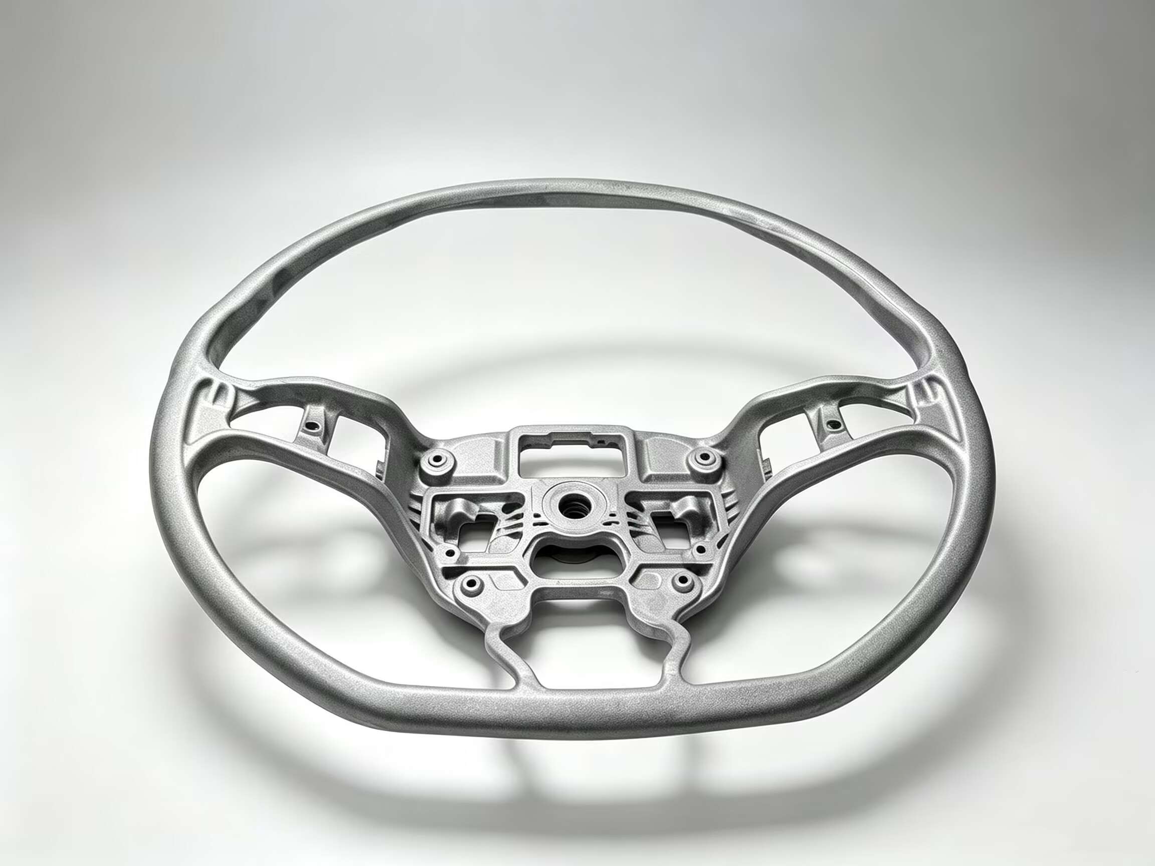
你有没有试过用拇指划过新的塑料部件,然后感觉到那条尖锐难看的凸起硌得皮肤生疼?那就是…… 分型线.
这本应是一个无缝过渡——但往往事与愿违。 瘢痕 仓促设计。
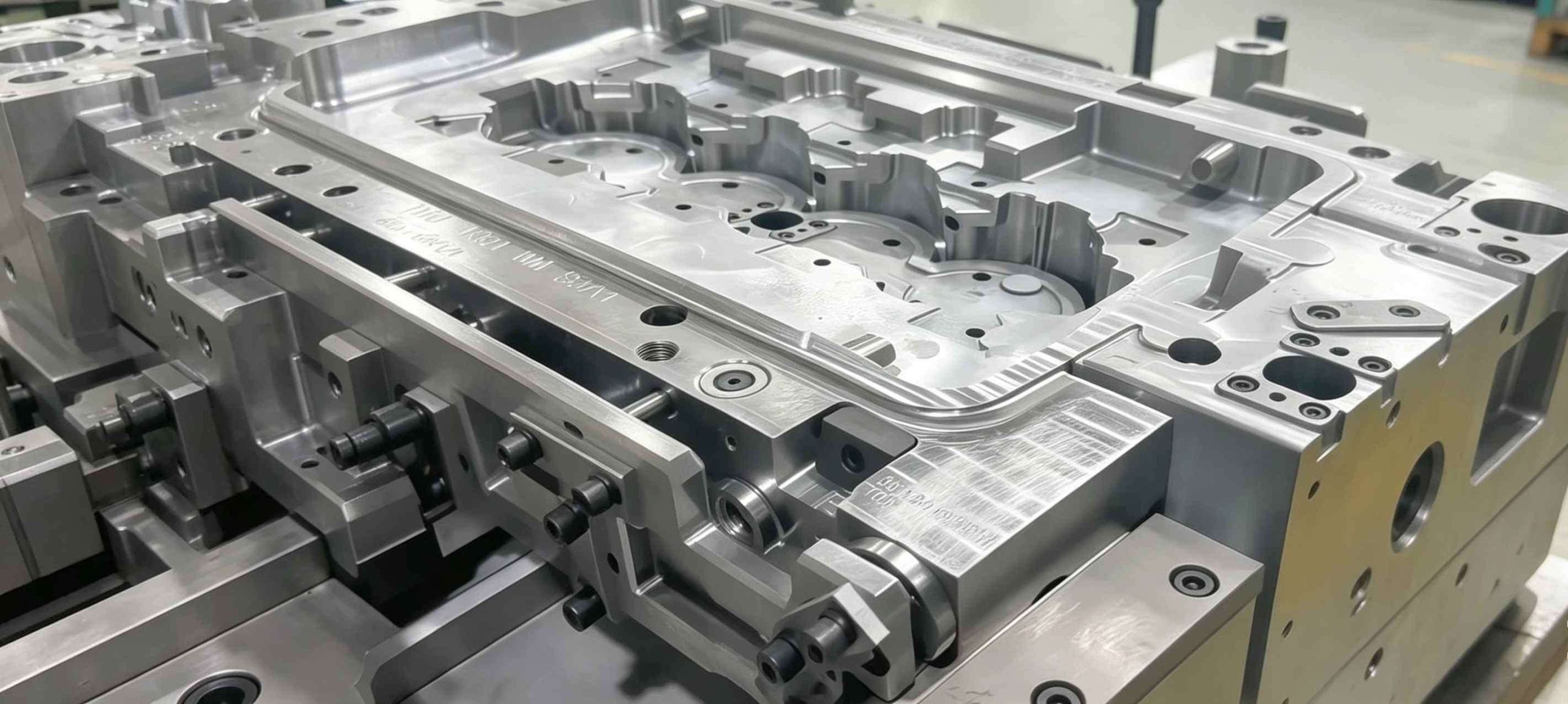
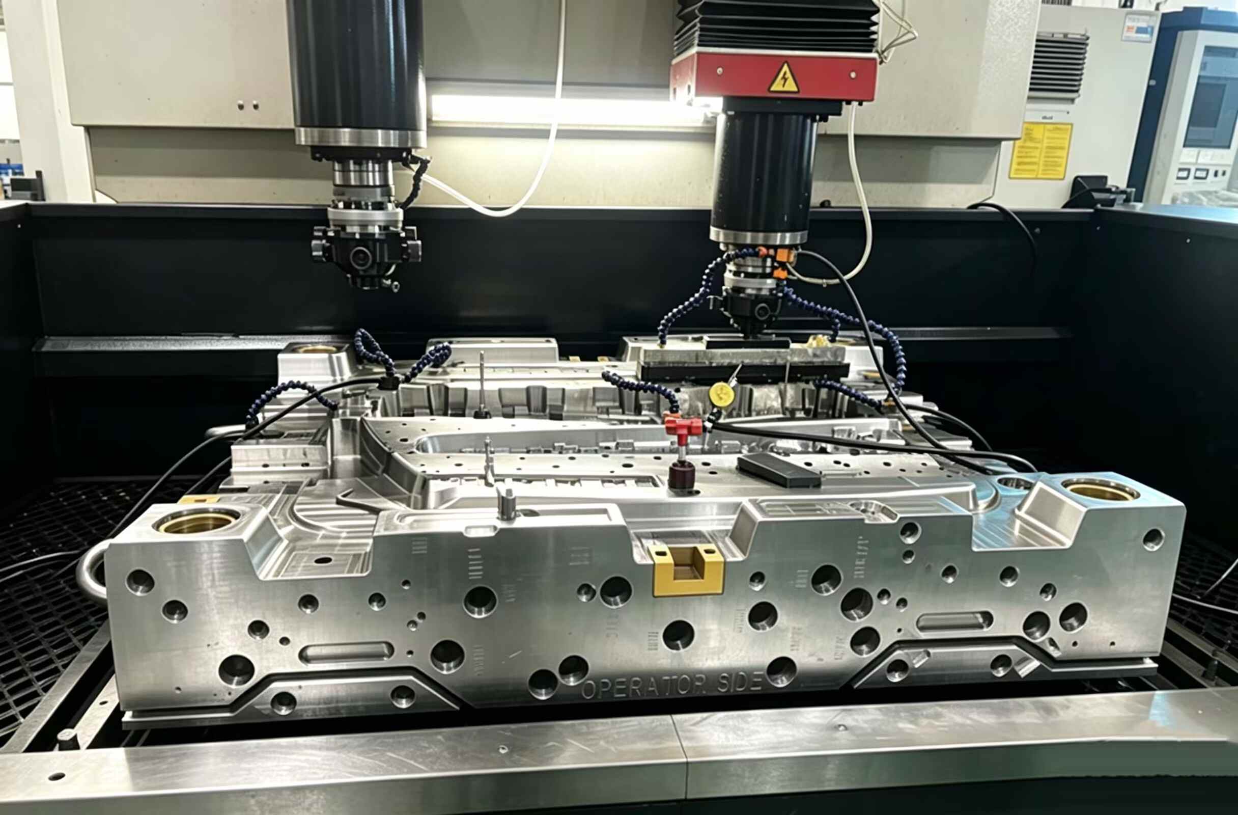
在二维CAD屏幕上,分型线看起来像一个简单的交点。但在车间里,它却是一个充满风险的战场——在这里, 芯腔相遇如果这两部分不能完美“吻合”,那么你的部分在印刷出来之前就已经受损了。
设计糟糕的分缝线不仅碍眼,而且还会…… 利润杀手:
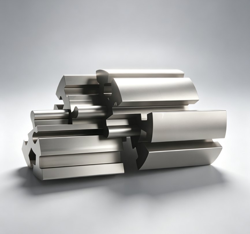
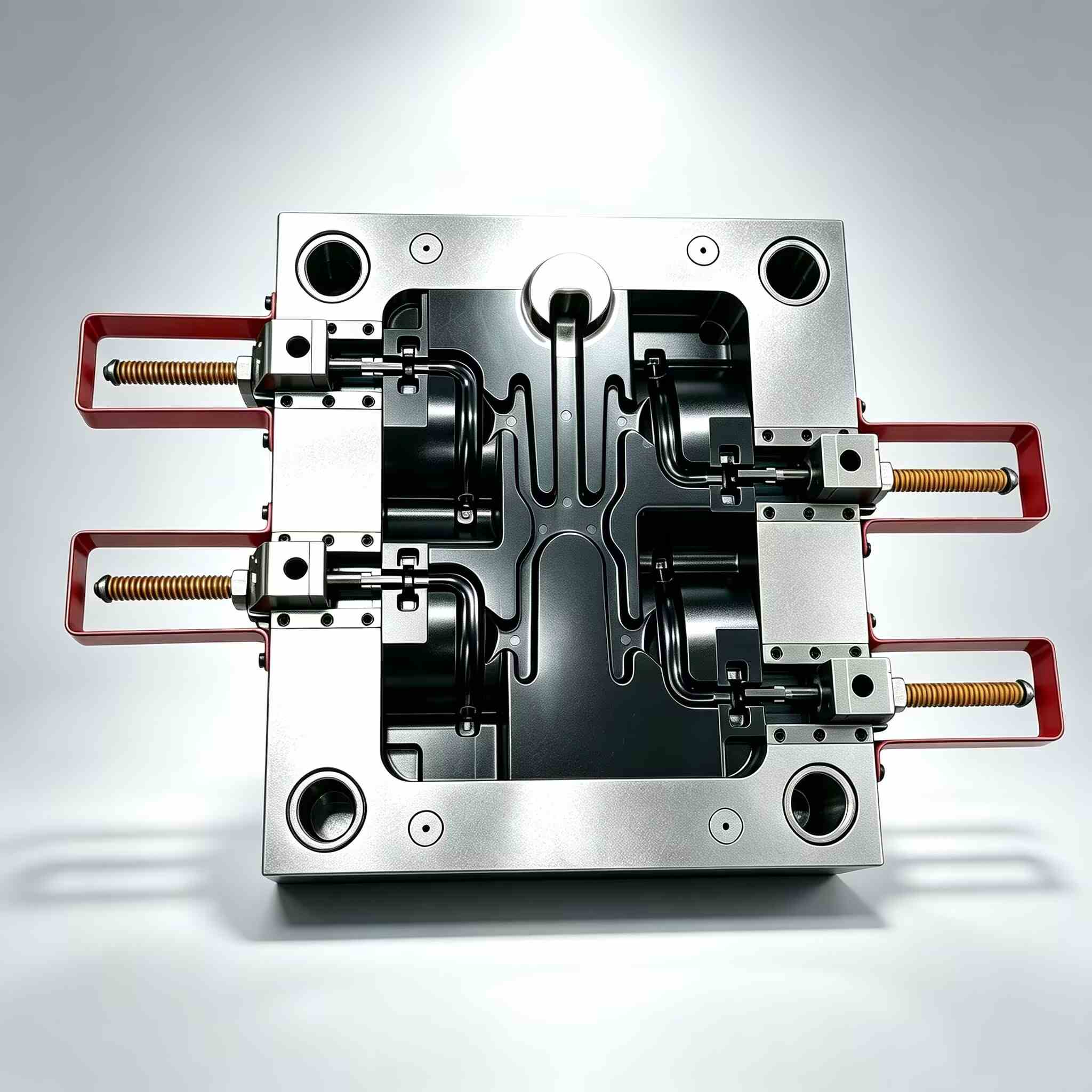
把分界线想象成…… 机械赤道 你那部分。
它决定了你的零件能否从模具中取出,还是会被困在模具里。
� “被困”的噩梦(Undercuts)
分型线哪怕偏差1毫米,也会造成…… 底切.
现在,你原本简单的模具突然需要:
➡️ 结果:模具成本可以 立即翻倍
� “敷衍了事”的表面问题
分界线不仅仅是一条边界——它是一种 高压密封.
复杂几何形状,例如:
……导致磨损加剧和密封失效。
留着它 平坦的留着它 简单的.
如果你的部件边缘有细细的、不想要的毛边——你遇到的就是这种情况 闪光.
在店里,我们称之为 “流血。”
注射成型过程中,熔融塑料处于极高压力下,会从缝隙中喷出。 任何差距.
• 钢材疲劳
• 对齐不良
• “吨位陷阱”
增加夹紧力并不能弥补设计缺陷。
吨位越大,造成的损害就越大(例如通风管道压碎、钢板变形)。
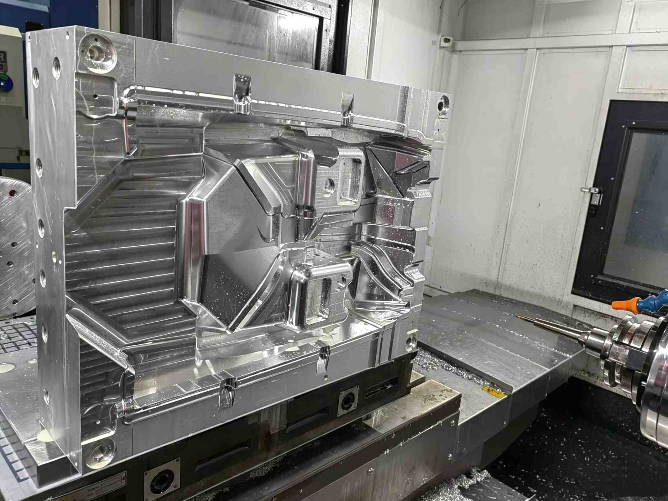
如果你在过程中看到闪光灯 首次T1试验:
� 这不是机器问题
� 这是 工具问题
修复 关闭对准而不是按键设置。
最好的告别语是…… 没人注意到.
像苹果或戴森这样的高端品牌都非常注重这个细节——你也应该如此。
✔ 跟随边缘
将分模线放置在尖锐的边缘或拐角处。
✔ 使用“分步”法
把它藏在里面:
✔ 纹理对比
➡️ 将缺陷转化为设计亮点
没有它,你就无法设计出合适的分型线。 吃水角度.
每面墙都必须从模具处逐渐变细。
更大的压电弧度 = 更容易弹出 + 更好的表面光洁度
设计师最常犯的错误之一:
设计完成后……就“把它扔过墙”交给模具制造商。
尽早与模具制造商接洽并询问:
几个小时 今天DFM讨论 可以节省:
分手线不仅仅是一条线——
这是设计与制造现实相遇的地方。
相关文章


联系我们