
剪线
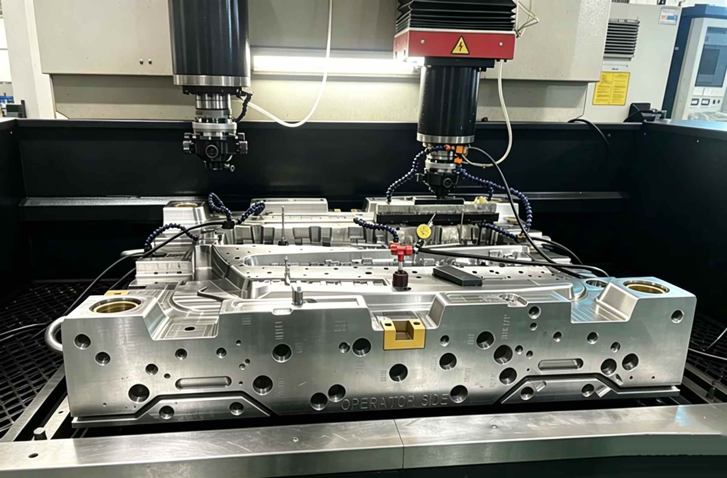
线切割放电加工 (Wire EDM) 通过在浸没于去离子水介质液中的工件和连续移动的黄铜或涂层线电极之间产生可控火花来切割导电材料。火花无需物理接触即可侵蚀材料——无需切削力、无需刀具压力、无需机械应力。这使得线切割放电加工特别适用于三类加工:硬度超过 HRC 55 且已进行热处理的硬化工具钢零件(使用硬质合金立铣刀会损坏这些零件);模芯、型腔镶件和量规所需的极高精度轮廓 (±0.003mm);以及任何铣削力都会导致变形的精细薄壁或小特征几何形状。在 XINKEY MOULD,线切割放电加工已集成到我们的模具制造流程中——硬化型腔板上的顶针孔、精密滑块导轨、脱料板轮廓以及冲压模具的切削刃,在热处理后均采用线切割放电加工至最终公差。我们使用标准黄铜丝(直径 0.25 毫米)进行一般加工,并使用涂层丝(直径 0.15-0.20 毫米)进行精细加工和高速切割。我们的线切割加工单元能够满足从单件特殊加工到刀片组批量生产的全需求。
- 公差低至±0.005毫米
- 表面光洁度 — Ra 0.4 µm 或更佳
- 适用于冲压模具和精密工具
- 切割硬化钢和硬质合金时无变形。
- 锥度切割范围最大可达±30°
- 产品详情
1. 本产品可以解决哪些问题?
模腔表面的重铸层和微裂纹
线切割放电加工固有地会产生一层薄薄的重铸层——金属熔化后在切割面上重新凝固——粗加工时通常为 2–5µm 厚,精加工时为 1–2µm 厚。在经历热循环的模腔表面(例如注塑成型、压铸),这层重铸层中含有微裂纹,这些微裂纹会在热应力作用下扩展,从而缩短模具寿命。XINKEY MOULD 通过程序控制多次精加工切削,每次切削的放电能量逐渐降低,将重铸层厚度减小到 1µm 以下,然后对模腔表面进行手工金刚石抛光,以彻底去除关键区域的残留层。
长时间无人看管的切割过程中电线断裂
对于大型工件,线切割放电加工通常需要无人值守地通宵运行。切割过程中断丝会浪费数小时的加工时间,并且需要重新穿线和重新定位——重新启动时还存在定位误差的风险。标准的线张力和冲洗设置对于较高的工件或冲洗不畅的几何形状来说通常过于激进。XINKEY MOULD 能够根据工件高度和切割几何形状优化线张力、冲洗压力和脉冲参数,采用断丝检测和自动穿线功能,并预先设置安全重入点,使机器无需操作员干预即可自主恢复。
尖锐内部轮廓的拐角精度损失
线切割放电加工 (Wire EDM) 会在尖锐的内角处自然形成圆角,这是因为线材本身具有直径 (Ø0.25mm) 以及过切火花间隙 (每侧 0.02–0.05mm)。对于设计有尖锐内角的特征,单次加工最多只能得到 R0.15mm 的圆角。XINKEY MOULD 提供一系列圆角控制策略:降低通过拐角的能量、补偿线材路径偏移,并在几何形状允许的情况下,设计拐角减薄结构,使配合的尖角部件能够完全贴合,而不会产生圆角干涉。
2. 典型应用
注塑模具型腔嵌件和型芯销
线切割型腔嵌件轮廓、芯销轮廓、脱料板开口和顶针孔——所有部件均在热处理后加工至 HRC 48–62。配合嵌件对之间的精度保持在 ±0.005mm,确保无飞边。材料:H13、D2、S136、M340 工具钢。
冲压模具和级进模具组件
用于钣金冲压模具的模板切削刃、冲头轮廓、脱料板和模钮孔。四轴锥度切削,用于加工模具后角——通常每侧0.5°–2°。材料:D2、SKD11、硬质合金(碳化钨牌号)。
精密量规、夹具和检测工具
用于制作通止规轮廓、三坐标测量机夹具板、装配夹具轮廓和设定标准件的加工件。线切割放电加工的精度可达±0.003mm,无需后续研磨即可获得规格级定位表面。适用材料:工具钢、不锈钢、硬质合金。
齿轮、花键和锯齿轮廓
定制正齿轮轮廓、内花键、同步带轮以及硬化轴和轮毂上的锯齿图案——直接根据 CAD 轮廓数据生产,无需成型工具或滚齿刀具。
医疗及微型组件
手术器械钳口轮廓、通道宽度小于 0.3 毫米的微流控模具嵌件以及采用生物相容性材料(316L 不锈钢、5 级钛)制成的种植体组件轮廓。使用细丝(Ø0.10–0.15 毫米)可加工内半径小至 0.10 毫米的微小特征。
3. 规格表
| 物品 | 细节 |
| 过程 | 线切割放电加工(线切割放电加工) |
| 线材类型 | 黄铜直径 0.25 毫米(标准);涂层线径 0.15–0.20 毫米(精细加工,高速) |
| 最大工件尺寸 | 500 × 400 × 250mm(具体尺寸取决于机器型号和几何形状) |
| 标准精度 | ±0.005毫米 |
| 可达到的精度 | ±0.003mm(采用优化的切割策略和环境温度控制) |
| 表面粗糙度 (Ra) | 两次精修可达到 Ra 0.8–1.2µm;四次及以上精修可达到 Ra 0.2–0.4µm |
| 锥形能力 | 最大角度±30°;四轴独立上下轮廓控制 |
| 最小内半径 | R0.10mm(配Ø0.15mm线径的导线);R0.15mm标准型(配Ø0.25mm线径的导线) |
| 材料能力 | 所有导电金属:工具钢(H13、D2、SKD11、S136)、硬质合金、不锈钢、钛、铜、黄铜、铝 |
| 硬度极限 | 无限制——可切割硬度高达 HRC 65 的全硬化钢(硬质合金可达 HRA 92) |
| 批量处理能力 | 从单件生产到批量生产;多个工件堆叠以生产相同型材 |
| 交货时间 | 单次植入:2-5天;批量植入:5-10天,具体取决于数量和植入方案的复杂程度。 |
| 质量控制 | 可根据要求进行三坐标测量机轮廓检测、表面粗糙度测量、边缘质量光学比较仪检测以及重铸层显微镜检测。 |
| 设计文件格式 | 2D DXF/DWG 用于轮廓几何形状;3D STEP/IGES 用于参考上下文 |
4. 项目流程与质量控制
第一阶段:面向制造的设计与布线路径规划
行动:审查线切割加工的零件轮廓:最小内半径与线径的关系、最大工件高度、锥度可行性、起始孔位置。生成线切割路径CAM:入口点、粗加工路径、精加工顺序、拐角控制参数。确定工件夹具方法。
质量控制重点:CAM仿真:线切割路径已验证,无碰撞,修剪切割顺序正确,拐角控制已激活。已估算每次粗加工和精加工的切割时间,以便安排生产计划。
第二阶段:工件准备和设置
行动:如果工件为封闭型材,则在焊丝入口处通过钻孔或小孔电火花加工加工一个起始孔(直径 1.0–2.0 毫米)。使用专用夹具或磁力卡盘将工件固定在机床工作台上。使用寻边和探针对准工件。将焊丝穿过起始孔。在介质槽中注入去离子水。
质量控制重点:工件对准:参考面上边缘定位精度为 0.005mm。使用垂直对准块进行导线垂直对准检查。介质水电导率 <10 µS/cm,温度 20 ±1°C。
第三阶段:粗加工
行动:使用针对材料类型和厚度优化的脉冲能量执行主轮廓粗加工。黄铜丝在工具钢上加工时,标准加工间隙为每侧 0.03–0.05 毫米。在整个切削过程中监测丝张力、冲洗情况和火花稳定性。
质量控制重点:过程监控:火花稳定性计读数在绿色区域内,无断丝。粗加工完成——轮廓尺寸与最终尺寸偏差在0.02mm以内。粗加工后表面粗糙度:Ra 2.5–3.5µm(典型值)。
第四阶段:精修以提高精度和表面光洁度
行动:执行预设的薄切工序(2-4道),逐步降低放电能量、降低线张力,并对每道工序进行偏移补偿。拐角处工序降低进给速度和能量。最后一道工序以最低能量进行,以获得最佳表面质量和最小重铸量。
质量控制重点:每次精加工后:在参考点进行尺寸检查。最终加工后:进行完整的三坐标测量,所有点的轮廓尺寸均在标称值的±0.005mm以内。表面粗糙度测量:达到Ra目标值。显微镜检查切割表面:火花纹路均匀,无线痕。
第五阶段:后处理和最终质量控制
行动:取出工件,清洁并去除入口/出口处的毛刺(如可触及)。对于模腔表面:按规定进行手工金刚石抛光,去除残留的重铸层。进行防锈处理。用保护性包装材料包装。
质量控制重点:最终三坐标测量报告:完整轮廓与CAD模型对比图及偏差图。表面粗糙度证书。关键拐角和边缘的光学比较仪照片。已进行防锈处理,包装安全可靠,便于运输。
5. 为什么选择新基模具
将线切割放电加工集成到模具制造工作流程中
在XINKEY MOULD,线切割并非外包给分包商的独立服务,而是我们模具制造流程中的核心内部能力。当您的注塑模具或压铸模具制造完成后,型腔镶件和型芯销会直接从热处理环节进入线切割工序进行最终轮廓切割。这避免了将线切割外包给第三方电火花加工车间时可能出现的精度损失、工期延误和沟通错误。
用于模具级表面处理的多层精加工程序
单次线切割会留下重铸层,且表面光洁度不适用于模腔。我们所有模具组件的标准配置为 2-4 次精切,将重铸层厚度降低至 1µm 以下,并直接从线材获得 Ra 0.2-0.8µm 的表面光洁度,从而最大限度地减少模具组装前所需的手工抛光时间。这样可以缩短整体交付周期,并确保模腔间表面质量的一致性。
通过三坐标测量机和偏差映射验证轮廓精度。
每套线切割模具镶件均附带一份三坐标测量机 (CMM) 轮廓测量报告,显示整个轮廓的实际尺寸与 CAD 设计的偏差。我们不宣称精度为 ±0.005 毫米——我们通过测量并向您展示数据来确保精度。对于多镶件型腔组,我们会测量并匹配镶件之间的轮廓,以确保无飞边闭合面。
DFM(设计制造)可在切割前发现角半径问题
线切割放电加工自然会将尖锐的内角圆化为线半径加上火花间隙。如果您的零件设计需要一个与之配合的尖角组件,我们会在开始线切割路径编程之前,在可制造性设计 (DFM) 中标记出来——建议使用角部倒角几何形状或可接受的最小半径——这样您在装配过程中就不会发现干涉问题。
6. 常见问题解答
Q1:线切割放电加工和传统铣削有什么区别?
传统铣削使用旋转的切削刀具与工件直接接触,产生切削力,这种切削力会使薄壁变形,并磨损硬化材料的刀具。线切割放电加工 (Wire EDM) 则利用移动的金属丝与工件之间的火花放电——没有切削力,没有刀具磨损,也没有机械应力。这意味着线切割放电加工可以加工完全硬化的钢材(硬度 HRC 60+),并能加工出铣削刀具难以加工的特征:例如锐利的内角、深而窄的槽以及厚度小于 0.3 毫米的壁厚。但缺点是,对于软材料上的简单几何形状,线切割放电加工的切削速度较慢,每小时成本也高于铣削加工。
Q2:线切割放电加工能否切割塑料或陶瓷等非导电材料?
不。线切割加工要求工件必须导电。金属(钢、硬质合金、铜、钛、铝)和导电陶瓷均适用。塑料、普通陶瓷、玻璃和复合材料不能进行线切割加工。如果您的零件不导电,我们将建议采用数控铣削或磨削作为替代工艺。
问题3:可实现的最小内角半径是多少?
使用标准直径 0.25 毫米的黄铜丝,最小内半径为 R0.15 毫米(线径 0.125 毫米 + 火花间隙约 0.025 毫米)。使用细直径 0.15 毫米的涂层线,我们可以达到 R0.10 毫米。对于需要真正锐利内角(接近 R0)的特征,需要进行设计减角或电火花加工后的手工锉削——我们会在可制造性设计 (DFM) 过程中标记这一点。
Q4:线切割放电加工是否会留下热影响区或重铸层?
是的——所有电火花加工表面都会形成一层薄薄的重铸层(金属重凝固层)。粗加工后,该层厚度为2-5µm,并可能存在微裂纹。经过2-4次低能量精加工后,重铸层厚度会降至1µm以下,微裂纹也会被最小化。对于注塑模具型腔表面,我们会通过手工金刚石抛光进一步去除重铸层。对于冲压模具的切削刃,这种薄的重铸层通常是可以接受的,不会影响模具性能。
Q5:线切割放电加工可以切割多大的零件?
工件最大尺寸约为 500 × 400 × 250 毫米,但实际尺寸限制取决于几何形状。高度超过 150 毫米的工件需要降低切削速度并仔细优化冲洗工艺。对于尺寸超过上述范围的大型模具板,我们可以考虑采用分段加工并配合装配销进行加工。
Q6:我需要 10 个相同的腔体嵌件——线切割放电加工可以批量生产吗?
是的。对于相同的型材,我们会将多个工件板堆叠起来,并作为一个整体进行线切割——所有镶件都使用完全相同的线切割路径,从而生产出几乎完全相同的型材,避免了因单独设置而产生的差异。这是多腔模具镶件组和冲压模具按钮组的标准做法。
Q7:线切割放电加工报价需要提供哪些信息?
请提供待切割轮廓的二维 DXF 或 DWG 文件,以及材料类型、厚度、数量、表面光洁度目标值 (Ra) 和任何锥度或四轴轮廓要求。三维参考文件 (STEP/IGES) 有助于理解切割路径,但 DXF 文件定义了切割路径。对于模具镶件加工,请提供配合组件的数据,以便我们验证镶件间的配合情况。
产品
最新消息
- 23rd 10 月 2026
Low-Volume Injection Molding: On-Demand Production & Fast Tooling
Why does Low-Volume Injection Molding Fit Uncertain Demand?
Low-volume injection molding gives you a production path when demand moves. You can make saleable parts, validate a design, and learn from field use before committing to a large steel tool.
On-demand production lets you buy smaller releases, keeping cash and warehouse space tied to real orders. Aluminum tooling can bridge a prototype and stable production. The choice depends on geometry, resin, quantity, and change cost.
When does On-Demand Production Make Sense?
Use it for a new product with uncertain demand, irregular replacement orders, or planned design revisions. It suits medical, laboratory, smart hardware, and industrial products that need hundreds or a few thousand validated parts. The run can expose fit, assembly, and surface issues while tool changes remain manageable.
What does Fast Tooling Change?
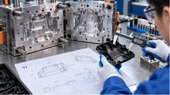
Fast tooling compresses the time between a frozen CAD file and useful parts. A practical route combines a rapid tooling review, mold design, CNC machining, trial molding, and a T1 check. The goal is a controlled learning cycle. Aluminum tooling can suit early production and provide data for a later hardened mold.
How does the Process Control Tooling and Production Risk?
Low-volume injection molding production still needs production-grade thinking. A short run can hide a poor gate or unstable cooling layout, then repeat the problem as demand rises. Review the part, mold, and press together so each decision has a measurable reason.
What Happens in an Injection Molding DFM Review?
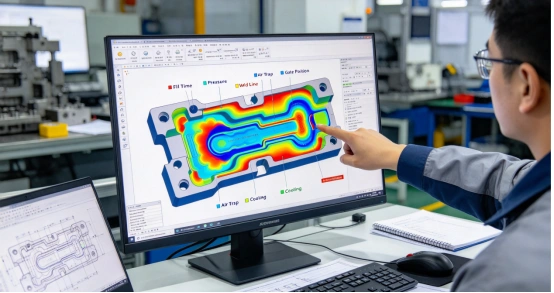
An injection molding DFM review checks wall thickness, draft, parting line, gate, venting, ejection, shrinkage, and press tonnage. Mold-flow simulation can show filling balance, air traps, weld lines, and cooling differences before steel is cut. This mold design for manufacturability step also flags undercuts that may need sliders, lifters, or inserts. Marked-up CAD views show the cost and schedule effect of each change.
How are Tooling and Samples Verified?
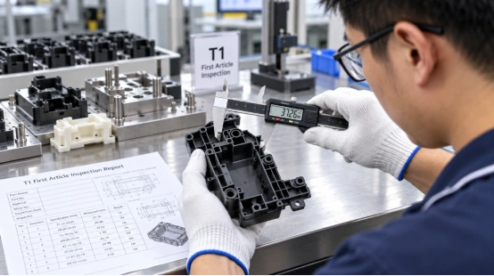
After machining, trial molding checks the cavity, runner, cooling, and ejection systems. Record T0 findings, correct root causes, and review T1 parts against the drawing. Ask for the inspection method, resin lot, and sample process conditions.
Which Quality Features Need a CTQ Plan?
Mark CTQ features where a dimensional shift affects sealing, fit, force, optics, or electrical safety. Link each CTQ to a gauge or CMM check, sampling frequency, and limit. This keeps a low-volume trial run useful for repeat orders and gives evidence beyond a visual sample.
Which Part Design Choices Affect Cost and Speed?
Part geometry sets much of your tooling cost before a purchase order. Design edits can shorten injection molding lead time, reduce secondary work, and simplify plastic injection mold maintenance.
How Much Draft Angle Do You Need?
Add a draft angle to faces that pull along the opening direction. Textured faces and deep ribs usually need more draft than smooth faces. Review the parting line with the ejection plan so the part stays on the moving side and leaves the cavity cleanly. This small check prevents drag marks, whitening, and stuck parts during sampling.
Why does Wall Thickness Matter?
Keep wall thickness as even as the function allows. A common starting range for many thermoplastics is about 1 to 3.5 mm, followed by a resin-specific review. Thick zones cool slowly and can create sink marks; thin zones can restrict filling. Use ribs, bosses, and gussets that support the part while keeping section mass compatible with the cooling cycle.
Where do Radii and Vents Help?
Use internal radii at corners to lower stress and match the cutting path of an end mill. Put vents near the end of melt flow so trapped air can leave. Good venting supports filling and reduces burn marks.
How should You Specify Surface Finish?
Choose the finish that matches function and viewing distance. A polished cavity adds hand work and schedule. A machined or light-texture finish may meet the requirement with a simpler tool. State the finish by area.
How should You Plan Quantity, Materials, and Tool Life?
Quantity planning connects your forecast to mold structure. Review the next 12 to 24 months, order pattern, and finished-goods cost before choosing cavity count or steel grade.
Is a Single-Cavity or Multi-Cavity Mold Better?
A single-cavity mold keeps early tooling and change work easier to control. A multi-cavity mold can lower the piece price when demand is steady, provided geometry and runner balance support even filling.
Family molds can combine related parts for a pilot production run, but each cavity needs its own inspection limits. Ask for a cycle-time and capacity comparison, then select cavities with demand in view.
Which Material Fits a Bridge Production Run?
Select resin by strength, heat, chemicals, color, and regulatory need. PP, ABS, PC, PA, POM, and filled grades differ in shrinkage and cooling. Share the final material early so gate, vent, cooling, and steel decisions match it.
When should You Move to a Hardened Tool?
Move when demand, wear, or dimensional stability justifies the capital. Aluminum tooling can carry early on-demand production and design learning. A hardened steel mold fits a repeat program with higher shot counts, tighter process windows, or long service expectations. Keep the CAD, inspection data, and approved process settings from the first tool so the next tool starts with evidence.
What should You Ask a Supplier Before Ordering?
Your supplier conversation should end with numbers, documents, and named owners. The checklist below helps you compare a quote by total project risk and tooling cost.
Which Questions Clarify the Real Schedule?
Ask for DFM timing, tool build days, first trial date, correction allowance, sample quantity, and the expected injection molding lead time. Confirm who approves material substitutions and how an engineering change affects the quote. A supplier that supports low-volume trial production should also explain how it will scale to small-batch production or bridge production after approval.
Which Records Support a Purchase Decision?
Request the DFM report, mold-flow findings when used, steel and heat-treatment records, CTQ dimensional reports, and the T1/T2 issue list. Ask how cooling, venting, ejection, and wear parts will be checked. These records support tool release.
Where Can Engineering Support Shorten the Route to Production?
For projects that need both rapid tooling and a low-volume injection molding production plan, XINKEY MOULD works from the product-design stage through DFM, mold design, machining, trial molding, and small-batch production. Its engineering workflow covers wall thickness, draft angle, gate and runner balance, flow analysis, cooling, venting, and ejection before tooling starts.
The team also handles sliders, lifters, inserts, threaded cores, and two-shot structures when the part needs them. Multi-stage machining checks and trial-molding verification create a traceable handoff into pilot production. If you need to compare a rapid prototype mold with a production-ready plastic injection mold, share the CAD file, resin, CTQ features, expected quantity, and target date so the quote reflects the actual decision.
FAQ
Q1: What is low-volume injection molding used for? A: It produces saleable parts for design validation, market testing, replacement demand, and early production before a larger tooling investment.
Q2: How does aluminum tooling affect fast tooling? A: Aluminum tooling supports quick machining and practical revisions for early runs. Tool life and resin choice still need a project-specific review.
Q3: What information should you send for an injection molding DFM review? A: Send the 3D CAD file, 2D drawing, resin and color, annual and first-run quantity, CTQ dimensions, finish callouts, and target date.
Q4: How long is the injection molding lead time? A: It depends on geometry, mold structure, material, inspection needs, and revision rounds. Ask for separate dates for DFM, tool completion, T1 samples, corrections, and shipment.
Q5: When does a multi-cavity mold make sense? A: It fits steady demand where balanced filling and shared inspection controls can lower the part cost. A single-cavity tool often suits early learning and changing designs.
- 22nd 10 月 2026
5 Benefits Of Rapid Tooling For Automotive Injection Molding
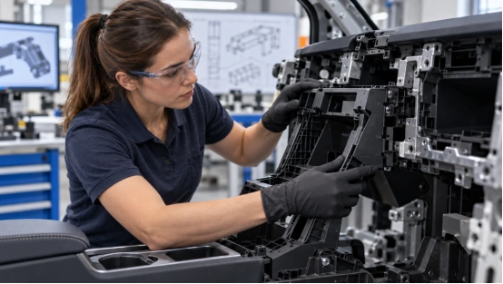
Car projects frequently shift. This usually happens once an initial physical part goes into a dashboard, console, lamp housing, or battery assembly. Rapid tooling for automotive injection molding offers a quick, manageable route. It takes you directly from CAD data to working parts.
These tools might rely on aluminum or soft steel. The exact metal depends on your target volume and chosen resin. The goal remains highly practical. You get to evaluate the piece and process. Plus, you can verify purchasing choices before paying for an expensive, long-lasting production tool.
What Is Rapid Tooling for Automotive Injection Molding?
It acts as a distinct mold-creation method. It fits automotive prototype production and medium-batch runs perfectly. A basic mold utilizes fewer cavities. It also features a very standard ejection setup.
Conversely, standard production molds require tough hardened steel. They need intricate slides, lifters, and balanced runners. Your final choice relies heavily on volume, geometry, resin, visual requirements, and strict delivery deadlines.
1. Faster Structural Changes Before Steel Commitment
The first physical sample exposes decisions that a screen can hide: a rib may interfere with a connector, a draft angle may hold the part on the wrong side, or a gate mark may land on a visible surface. A rapid prototype mold gives your design team a short feedback loop. You can review T1 samples, record the change, and update the part or mold while the project is still flexible.
How Does the Review Work?
Ask for DFM analysis before machining begins. The review should cover wall thickness, draft, parting line, undercuts, ejection, shrinkage, and the intended press.
The engineering record should also show which change affects tool cost, cycle time, or assembly fit. This makes a quote useful for purchasing because you can compare the cost of a revision with the cost of carrying a risky feature into production.
2. Earlier Validation of Automotive Plastic Parts
Automotive rapid injection molding lets you test structural features with a real molded part. Deep cavities, thin walls, ribs, bosses, and snap fits behave differently under filling, packing, cooling, and ejection. A digital model can guide the review, yet a physical sample still needs fit checks, load checks, surface review, and dimensional measurement.
Where Does Mold Flow Analysis Help?
Mold flow analysis maps gate position, runner balance, filling pattern, weld lines, air traps, shrinkage, and warpage and sink marks before steel is cut. The result is a mold design validation record that points to a specific action, such as moving a gate, changing a rib, adding a vent, or adjusting a cooling circuit.
For complex mold structures, this early work reduces the chance of discovering a slider, lifter, or insert problem during a late trial.
3. Better Control of Prototype Spending
Prototype tooling turns a large tooling decision into staged purchasing. You can order a defined quantity for fit, durability, and user testing, then decide whether the geometry merits a production tool. This fits projects that need low-volume injection molding for a pilot build, a customer trial, or a limited vehicle release.
What Should Purchasing Compare?
Compare the tool price with revision cost, resin usage, inspection time, machine size, and the value of the parts being tested. Ask whether the tool can be modified, whether wear parts are replaceable, and which dimensions will be measured on each sample.
A low entry price loses its value when the tool cannot support the next test or when every change requires a new build. A clear inspection plan also helps engineering, quality, and purchasing agree on the release decision.
4. Shorter Lead Times for Testing and Launch Decisions
Rapid tooling for automotive parts can move first shots into a working press in days or a few weeks, depending on geometry, material, and tool construction. CNC-machined aluminum or soft tooling often suits an early run. The supplier still needs time for design review, machining, assembly, trial molding, and corrections, so a realistic schedule matters more than a headline number.
Which Process Details Affect the Schedule?
Injection molding cycle time depends heavily on wall thickness, resin, mold temperature, and cooling layout. Well-planned mold cooling channels remove heat from thick areas and reduce the wait before ejection. Venting, runner balance, and a stable ejection system also affect the number of trial loops. When you request a quote, ask for milestones for DFM approval, steel release, first trial, dimensional report, and sample shipment.
5. A More Practical Mass Production Transition
Rapid tooling can use production-grade plastics, so the samples can represent the mechanical behavior, appearance, and assembly feel expected from the final part. The tool itself may have a shorter service life than a hardened production mold. That distinction should be written into the sourcing plan.
How Do You Plan the Handover?
Carry the approved CAD revision, resin grade, shrinkage data, gate location, cooling notes, and inspection results into the automotive injection molding tooling package.
A multi-cavity mold may need a new runner balance study and a different press condition. Treat the prototype run as process learning: record fill time, packing, cooling, ejection, and key dimensions. Those records shorten the mass production transition and give the production team a starting process window.
What Should You Look for in a Rapid Tooling Partner?
The practical value of a rapid tool comes from decisions made before cutting steel. XINKEY MOULD uses an engineering-first workflow that starts with DFM analysis and mold flow analysis, then moves through mold design, precision machining, trial molding, and verification.
Its team includes 22 in-house designers, with support for rapid T1 samples, low-volume injection molding, sliders, lifters, inserts, hot or cold runners, and cooling-system design. The automotive workflow includes an IATF-aligned process and PPAP documentation available on request.
For buyers comparing suppliers, the useful question is whether the same team can carry approved changes into production tooling. Its injection mold engineering solutions cover that design-to-sampling handoff and keep the release record tied to the mold revision.
FAQ
Q1: What is rapid tooling for automotive injection molding used for?A: It produces early automotive plastic parts for fit checks, functional tests, pilot builds, and market or customer review before a long-life production mold is released.
Q2: When should you request DFM analysis?A: Request DFM analysis before steel machining. Review wall thickness, draft, parting line, gates, ejection, cooling, shrinkage, and press requirements while design changes remain manageable.
Q3: Can rapid tooling support PPAP documentation?A: The supplier can prepare PPAP documentation when the project quality plan calls for it. Confirm the required records, dimensional reports, material certificates, and process data before the first trial.
Q4: How fast can a rapid prototype mold deliver T1 samples?A: A simple tool may reach T1 samples in days or a few weeks. Geometry, resin, tool material, cavity count, and the number of trial corrections set the actual schedule.
Q5: Does rapid tooling replace a production mold?A: It supports prototype and bridge quantities. A hardened production mold is usually required for high shot counts, multi-cavity output, tight process control, and long service life.
- 15th 10 月 2026
5 Strategic Benefits of Outsourcing Rapid Tooling
A launch date can slip long before the first molded part. The delay often starts with a wall thickness that traps heat, a weak draft angle, or a late gate decision. Outsourcing rapid tooling puts engineering, machining, trial molding, and measured samples on one project path.
A capable tooling supplier connects speed with part quality and a credible route to production through rapid tooling services.
Benefit 1, Shorten Your Time to Market
Rapid tooling compresses the work between a released CAD file and a tested molded part. Engineering review, material planning, mold design, and machine scheduling can start from the same controlled data set.
Run Design and Manufacturing Work in Parallel
An outside team can review draft, wall thickness, undercuts, parting lines, gate position, ejection, and cooling while your product team closes cosmetic details. That overlap may remove several handoffs. It also gives procurement one schedule covering tool design, machining, assembly, trial, inspection, and sample shipment.
Set a Clear Sample Milestone
Ask the supplier to quote a date for T1 samples and list the inputs that control it. Standard tools may reach T1 in two to four weeks. Unscrewing or two-material tools can take four to eight weeks. Complexity, steel choice, bought-in components, and CAD changes still affect time to market.
Benefit 2, Turn Tooling Cost into a Controlled Project Budget
Internal tooling requires design hours, CNC and EDM capacity, assembly skill, press time, metrology, and corrections. Outsourcing places those items inside a defined project scope for comparison against launch volume.
Compare the Full Cost of Ownership
Compare quotations by total project cost. Repeated sampling, steel welding, long cycles, and early wear all add expense. Ask each tooling supplier to state the mold steel, expected life, cavity count, runner type, replaceable wear parts, inspection scope, trial rounds, and change policy.
Match the Tool to Expected Volume
A rapid prototype mold can use a simpler layout and steel suited to design validation or an early market run. A production tool needs balanced cooling, durable sliding parts, controlled hardness, and maintenance access. Share annual volume and likely product revisions before the quote.
Benefit 3, Find Design Risks Before Steel Is Cut
Small CAD choices can create large tool changes. Thin ribs may fill poorly, thick bosses can sink, limited draft can mark the surface, and an undercut may require a slider or lifter. Early engineering review gives you time to change the part file while the change is still simple.
Review the Part through DFM
A useful DFM analysis marks wall thickness, draft, shutoffs, parting lines, ejection points, tolerances, surface requirements, and assembly interfaces. It should also explain why each item matters.
For example, keeping a concentric bore on one mold half reduces mold-shift and tolerance-stack risk. A purchasing team can then approve the tool scope with visible technical reasons.
Test Flow, Cooling, and Warpage Digitally
Mold flow analysis can compare gate positions, pressure, weld lines, air traps, shrinkage, cooling, and warpage before machining. Moving a gate 5 mm in a simulation is a short task. A change after steel cutting can require welding, machining, polishing, and another trial.
Benefit 4, Validate Materials with Production-Like Parts
A printed prototype answers fit and appearance questions. It rarely reproduces resin flow, fiber orientation, shrinkage, weld lines, sink, or ejection behavior from molding. Rapid injection molding gives you parts made with the intended resin and a process close to the planned production method.
Test the Resin in the Intended Process
Use molded samples to compare candidate resins for stiffness, impact, heat, chemical exposure, sealing, color, and surface finish. Process details matter. Phenolic materials, for example, require controlled mold heat and effective venting. Insert-molded parts need secure insert location under injection pressure. Two-material parts need a sound bonding interface and accurate tool alignment.
Use Measured Samples for Decisions
Define the sample plan before the tool trial. Record resin grade, drying condition, melt and mold temperatures, pressure, cycle time, and cavity number. Then inspect critical dimensions and run the product tests that decide release.
A nice-looking sample can still hide a weak process window. Measured evidence gives engineering and purchasing the same basis for approval.
Benefit 5, Create a Practical Bridge to Mass Production
The first acceptable shot proves that the tool can make a part. Pilot runs test repeatability across cavities, shifts, and material lots. Outsourcing rapid tooling delivers the planned value when one team carries the project through sampling and early production.
Stabilize the Process during Pilot Runs
Low-volume production and bridge production let you supply launch units while the team checks cycle time, scrap, dimensional drift, assembly fit, packaging, and maintenance needs. Engineers can tune cooling, venting, packing, and ejection with direct access to the tool. That continuity matters when a defect appears only after a longer run.
Protect Return on Tooling Investment
Earlier sales help recover the tool investment, though repeatable output drives the larger return. Review yield, labor content, resin use, cycle time, press tonnage, and wear-part access. A parting-line choice that lowers projected area may allow a smaller press. A hot runner may cut runner waste at high volume. Each decision should connect to your forecast and unit-cost target.
What Should You Expect from an Engineering-Led Tooling Partner?
The five benefits depend on one connected engineering record from DFM through trial molding. XINKEY MOULD assigns 22 in-house designers to product review, mold design, and mold flow analysis. Its documented process covers wall thickness, draft, parting lines, sliders, lifters, cooling, venting, ejection, and material selection before machining. High-precision CNC work reaches ±0.01 mm-level control, and molding equipment spans 90T to 750T for sampling and production handoff.
For a buyer, the useful point is continuity. The same project can move from a 24-hour DFM report to tooling, T1 inspection, pilot quantities, and injection mold manufacturing. That structure makes design changes, sample findings, and production settings easier to trace. You can request a project review with the CAD file, resin, annual volume, finish, tolerance, and target sample date.
FAQ
Q1: When Should You Outsource Rapid Tooling?
A: Outsource when your launch plan needs molded parts sooner than your internal engineering, machining, or press capacity allows. It also suits projects that need DFM, material trials, or a direct path into pilot production.
Q2: What Files Should You Send for a Rapid Tooling Quote?
A: Send a 3D CAD file, a dimensioned drawing, resin grade, surface requirements, critical tolerances, annual volume, target tool life, and the required T1 date. Add assembly data when mating parts control fit.
Q3: How Can You Compare Tooling Quotes Fairly?
A: Compare steel, cavities, runner system, mold standard, expected life, inspection scope, trial rounds, sample quantity, change terms, lead time, and shipping. A line-by-line comparison reveals what each price includes.
Q4: Can Rapid Tooling Use Production Resin?
A: Yes. A suitable mold can run production resin for functional, dimensional, and assembly tests. Confirm drying, processing temperature, shrinkage allowance, and any fiber or flame-retardant content before tool design.
Q5: Can a Rapid Tool Move into Mass Production?
A: Some tools can support continued production when their steel, cooling, cavity layout, wear parts, and press interface match the volume target. Ask the supplier to state the expected shot life and maintenance plan in the quote.
- 16th 10 月 2026
The Strategic Advantages of Short-Run Injection Molding for Complex NPI
Complex new product introduction (NPI) projects rarely fail because the CAD model looks wrong. They fail when a part reaches steel, trial molding exposes a gate or cooling issue, and the schedule has no room for another tooling loop.
Short-run injection molding gives you production-like parts early. You can check fit, function, finish, assembly, and customer response before a full-volume tool absorbs the budget.
What Does Short-Run Injection Molding Add to NPI?
Short-run injection molding uses a production-intent mold and a controlled quantity of parts for design validation, pilot production, or bridge production. The run can be sized around a test plan, such as 100 parts for assembly checks or several thousand parts for a market release. Molded parts and process data provide the evidence for the next tooling decision.
A Physical Test of the Product
Resin shrinkage, weld lines, ejection marks, and actual assembly loads appear in molded parts. A printed model cannot show how a thin wall fills or how a snap fit behaves after cooling. Early molded samples let your team record dimensional data and make a change while the tool remains practical to modify.
A Bridge Between Design and Volume
Bridge production gives you sellable or field-test units while the final multi-cavity tool is being completed. This matters for a new medical accessory, smart device housing, or industrial enclosure with a fixed launch date. The same material family, gate concept, and process window can carry the project into the next tool stage.
Which NPI Risks Can You Control before Full-Volume Tooling?
The largest NPI costs often come from late engineering decisions. A short run creates a checkpoint for the decisions that affect tooling cost, yield, and delivery.
Part Design and DFM Analysis
Start with DFM analysis before cutting steel. Review wall thickness, draft angles, ribs, bosses, undercuts, parting lines, and the projected area that drives press tonnage. A small change to a rib or draft can remove a difficult slide, simplify machining, and reduce a later mold revision.
Flow, Cooling, and Ejection
Moldflow analysis can compare gate positions, runner balance, filling patterns, air traps, and weld lines. Cooling channel layout matters because cooling often occupies about 70% of an injection cycle.
Uneven thermal balance creates sink marks and warpage. Venting gives trapped gas a path out, while a balanced ejector pin, sleeve, lifter, or air-ejection system protects cosmetic surfaces during release.
Complex Geometry and Tolerance
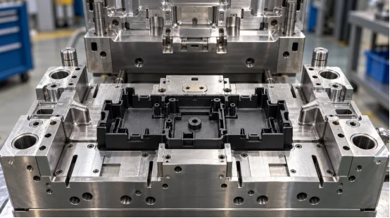
Sliders, lifters, inserts, threaded cores, and two-shot features add movement and tolerance stack-up. A short-run tool lets you inspect those interfaces under real pressure. Check core and cavity alignment, guide pins, runner balance, and the fit of mating features before you commit to a larger cavity count.
How Should You Compare Short-Run Tooling Cost with Production Tooling?
Price the decision across the whole NPI path. A low quote becomes expensive when it creates extra sampling, hand rework, scrap, or a rebuild. A practical sourcing review should include tool steel, machining, trial molding, material waste, engineering time, freight, and the cost of a delayed launch.
Use Volume and Risk Together
Choose a cavity count that matches the validation need. A single-cavity or low-cavity mold can provide fast feedback for a complex enclosure. A multi-cavity tool makes sense after dimensions, resin, and assembly have settled. For high-cycle projects, steel selection and heat treatment affect wear parts, maintenance, and stable output.
Set Acceptance Data Before the Run
Define critical dimensions, cosmetic zones, cycle time, part weight, flash limits, and assembly tests before ordering. Ask for T1 samples, a measurement report, and a short list of open issues. This gives procurement a clear release gate and gives engineering facts for the next tool decision.
What Does a Reliable Short-Run Process Look Like?
The process should connect design review, mold design, machining, trial molding, pilot production, and mass production. Each handoff needs an owner and a measurable output.
A Practical Sequence
Share the 3D data, resin, annual volume, key dimensions, and launch date.
Complete DFM analysis and review Moldflow findings with the design team.
Select the parting line, runner, cooling, venting, ejection, and mold steel.
Machine and assemble the tool, then run T0 or T1 samples.
Measure parts, test assemblies, and record process settings.
Correct the tool or part design, then release a controlled pilot production run.
This sequence keeps the evidence close to the decision. It also makes a handoff to a higher-cavity tool easier because the team has a record of what worked.
How Can an Engineering-Led Supplier Support Complex NPI?
XINKEY MOULD supports short-run injection molding as part of an injection mold engineering workflow. The team starts with DFM analysis, wall thickness and draft review, and Moldflow analysis before tooling. It then connects precision CNC machining, EDM, mold assembly, trial molding, and low-volume production support.
For complex NPI, the useful detail is the handoff: T1 samples are checked against design intent, cooling and venting are reviewed against defects, and slider, lifter, insert, or threaded-core behavior is tested before a volume decision.
The process also covers rapid prototype mold development, pilot production, and bridge production, so procurement can compare a tool plan with a real launch schedule. See the injection mold engineering solutions and custom injection mold products pages for the relevant service scope.
FAQ
Q1: When should you choose short-run injection molding for NPI?
A: Choose it when fit, function, finish, assembly, or market timing needs evidence from production-intent parts before full-volume tooling.
Q2: Can low-volume injection molding use the final production resin?
A: Yes. Use the approved resin grade when the tool, press, and process window support it, then record material lot and drying conditions with the samples.
Q3: How do T1 samples help a procurement decision?
A: T1 samples connect the quoted tool design with measured dimensions, defects, cycle data, and open engineering actions, giving procurement a clear release gate.
Q4: Does a complex injection mold require Moldflow analysis?
A: Moldflow analysis is useful when gates, thin walls, multiple cavities, cooling balance, air traps, or weld lines create meaningful process risk.
Q5: What should you request before pilot production?
A: Request an approved drawing, resin specification, dimensional report, cosmetic standard, process settings, open-issue list, and a correction plan with owners and dates.
- 9th 10 月2026
原型注塑成型 vs 3D 打印 vs CNC 加工
选择原型制作工艺取决于您需要零件解答的问题。例如,用于装配检查的外壳、卡扣式盖子和十件试生产所需的证据各不相同。本指南从交付周期、材料性能、精度、表面光洁度、数量和采购风险等方面对原型注塑成型、3D 打印和 CNC 加工进行了比较。
每种塑料原型制作方法都能生产出什么样的产品?
这三种方法制造零件的方式各不相同,因此零件所承载的证据也各不相同。注塑成型是将熔融的热塑性塑料注入型腔,并重复相同的循环。3D 打印是逐层添加材料。CNC 加工是从实心块体上去除材料。您的预期用途应该决定哪种方式最为重要。
原型注塑成型
原型注塑成型使用小批量模具(通常为铝或较软的工具钢)来制造计划生产所需的树脂零件。您可以检查成型零件的熔接线、缩痕、翘曲、卡扣力以及表面纹理。
3D打印
3D打印适用于日常几何形状的改变或一到五个快速零件的打印。FDM技术可使用ABS、PLA和聚碳酸酯等材料;树脂和粉末系统则可实现更精细的细节。层方向会影响强度、阶梯状纹理和热响应。使用相同标称聚合物的3D打印铰链的弯曲性能可能与注塑成型的铰链不同。
数控加工
CNC加工从ABS、POM、尼龙、PC或其他工程塑料块上切割零件。它能提供清晰的基准面和精确的尺寸,尤其适用于易于加工的特征。内部通道、深腔和薄肋会增加成本,因为刀具需要操作空间和支撑。加工后的零件还会保留塑料块的纹理和刀痕,这可能与模压成型的纹理有所不同。
图片:数控铣床主轴雕刻白色塑料原型零件.webp
哪种方法最适合您的数量和交货时间?
数量会影响成本曲线。在比较报价之前,请设定目标数量、样品日期和设计修改次数。
一至十部分
3D打印适合早期形状检查,因为无需专用模具。CNC加工适合需要精确孔径、平面基准或功能性螺纹的零件。当决策涉及模塑件的性能时,例如活动铰链或夹子,注塑成型原型则更为合适。
十到几百份
小批量注塑成型可以将模具成本分摊到可重复生产的零件上,并支持使用生产级材料。过渡模具可以在准备更长寿命模具的同时提供试制件或可销售的成品。CNC加工适用于厚重、刚性零件;3D打印则增加了去除支撑、打磨或定向检测等功能。
进度计划
文件准备和排程完成后即可开始3D打印。CNC加工时间取决于编程、材料、夹具和表面处理。标准的快速模具项目大约需要两到四周才能完成T1样品;滑块、嵌件、拆卸系统、特殊钢材或高要求的表面处理可能会将制作周期延长至四到八周。请与供应商确认各个阶段的里程碑。
材料和零件性能对比如何?
材料的选择应根据使用条件而定,例如冲击、高温、化学品腐蚀、弯曲、外观或电绝缘性能。使用替代树脂会导致关键性能问题无法解决。
生产级树脂证据
注塑成型工艺可让您在可控的条件下测试ABS外壳、PC冲击部件、PP活动铰链、PA填充部件以及各种填充型材料。树脂干燥、熔体温度、保压压力和冷却都会影响收缩率和翘曲度。PP具有耐化学性和柔韧性;填充型PA可增加刚度,但会增加模具磨损。
印刷和机械加工材料的限制
打印部件可能存在空隙、层间接缝或强度不均匀等问题。CNC加工部件使用预制材料,但切割过程可能会暴露应力或导致薄壁变形。对于热老化、化学腐蚀或重复组装等情况,测试样品应与最终使用的树脂和工艺相匹配。
哪种方法能获得合适的精度和表面光洁度?
精度取决于每个特征的具体情况。基准策略、收缩率、工具使用、检测方法和热历史都会对其产生影响。
准确性和细节
CNC加工能够对可加工的表面和孔保持严格的公差,因此非常适用于量规和配合研究。数字化构建直接形成复杂形状,最终打印件保留了构建表面;模具分型线并不决定其几何形状。
小孔和边缘可能需要后处理。注塑成型工艺稳定后,型腔几何形状会重复出现;DFM(面向制造的设计)评审必须考虑拔模斜度、分型线、浇口、顶出和树脂收缩等因素。
表面处理和外观
机加工表面会留下刀痕,可以进行抛光或纹理处理。印刷表面通常需要打磨或蒸汽处理。模腔在每次注塑成型后都能保持特定的抛光或纹理效果。浇口痕迹、熔接线、顶出痕迹和光泽度差异都应在图纸上标明,尤其是在外露部件上。
购买对比中应该包含哪些内容?
有用的报价将价格和时间与明确的范围挂钩。比较工程量、材料、检验、修改、交付方式和单价。
报价清单
请提供三维模型、带尺寸标注的二维图纸、树脂牌号、颜色、表面处理、数量、年度预测、关键公差、装配环境以及所需的样品日期。请询问模具材料、型腔数量、流道类型、模具寿命目标、试模、T1报告、纠错政策以及所有权条款。
对于数控加工,请列出原材料、基准方案、检测点和表面处理工艺。对于印刷,请具体说明工艺流程、方向、层高、后处理工艺和受力方向。
DFM 和审判记录
面向制造的设计 (DFM) 和 DFM 分析应在金属切削前标记壁厚、拔模斜度、加强筋、凸台、倒扣、浇口、排气孔和顶出等问题。在 T0 和 T1 阶段,记录短射、飞边、烧焦、缩痕、熔接线、粘连、翘曲和尺寸偏差。将每个问题与相应的操作和负责人关联起来。该记录为采购部门批准下一模具或修改零件提供了明确的依据。
工程合作伙伴如何将原型结果与生产联系起来?
当原型机暴露出模具或工艺问题时,交接环节至关重要。设计逻辑应贯穿整个评审过程,包括模具修正、试模以及小批量生产决策。
XINKEY MOULD 将此工作流程应用于塑料零件开发。其工程师在模具制造前会审查壁厚、拔模斜度、收缩率、浇口、流道、冷却、排气、顶出和模具强度。对于侧孔、螺纹或双材料特征,其范围包括滑块、顶杆、镶件、螺纹型芯、自动脱模装置和 2K 双色注塑结构。CNC、EDM 和线切割等加工方式支持模具制造,加工控制精度可达 ±0.01 mm(在特征和检测方法允许的情况下)。
作为一家塑料注塑模具制造商,它将试验结果应用于模具修正和小批量注塑成型,并将样品数据与生产联系起来。
常问问题
问题1:对于20个零件来说,原型注塑成型值得吗?
是的,如果您严格要求使用生产级树脂、模压成型的夹子、铰链或特定纹理。只需权衡一下工具的前期成本与自行加工或打印每个零件的成本即可。还要考虑您对可靠、稳定的性能有多看重。
Q2:3D打印可以取代注塑成型原型吗?
只能说部分如此。3D打印在处理基本形状、间隙和早期人体工程学检查方面表现相当不错。然而,注塑成型则展现了截然不同的细节。它能精确地展示型腔填充过程,突出真实的收缩和潜在的熔接线。此外,它还能演示实际的脱模过程和树脂的真实性能。
Q3:何时才是CNC加工的实用选择?
当您只需要少量刚性零件,且对基准面、孔或螺纹的精度要求极高时,它就能发挥出色作用。对于体积较大的几何体,它也是明智之选。打印厚截面耗时过长。此外,小批量生产也无法抵消定制模具的成本。
Q4:最终塑料材料用于哪个工艺?
注塑成型通常使用预先设计好的树脂。数控加工依赖于标准工程塑料坯料。而3D打印则仅限于适用于特定打印机的聚合物。因此,在得出任何最终性能结论之前,务必核实热性能、化学性能和强度规格。
Q5:何时应该从原型模具过渡到生产模具?
只有在设计完全稳定后才能进行过渡。您的 T1 样品也必须通过所有基本验收标准。此外,您的预计产量必须足以支持购买寿命更长的模具。请根据原型运行的可靠数据做出明智的选择,这些数据包括:记录的周期时间、实际废品率、实际维护需求和已验证的单位成本。
- 2026年10月2日
快速原型注塑成型:塑料零件开发实用指南
CAD模型看起来可能已经完成,但注塑成型的零件仍然存在一些问题。加强筋会下陷吗?卡扣能经受住组装吗?外壳会围绕按钮变形吗?快速原型注塑成型技术使用预先设计的树脂制造出实际的注塑零件,从而解答这些问题。
该方法适用于需要进行功能测试、试生产、客户样品或早期销售样机的塑料零件开发。速度优势在于:在金属切削开始之前,就已明确了刀具的选择范围并完成了必要的工程设计工作。
什么是快速注塑成型?
快速注塑成型使用快速制造的模具来生产可重复的塑料零件。许多团队也称之为原型注塑成型或快速模具制造。该工艺遵循与生产成型相同的基本流程:夹紧、注射、保压、冷却、开模和脱模。
它与生产工具的区别
注塑模具原型通常使用铝、P20、NAK80 或更硬的嵌件来制作耐磨部件。数量、树脂、表面光洁度和公差是选择嵌件的关键因素。铝材适用于小批量生产。P20 便于焊接和设计修改,而 NAK80 则适用于抛光表面。
生产工具可能包含多个型腔、硬化钢材、热流道、自动化操作和可更换的易损件。快速模具可确保成型过程与当前测试目标保持一致。
何时应该使用快速模具?
当打印或机械加工的原型无法解答下一个工程问题时,应使用快速模具。模塑树脂在焊缝、活动铰链、卡扣配合、凸台和纹理壁等部位的性能会有所不同。
功能验证和试运行
使用生产级材料测试刚度、耐化学性、热响应或装配力。ABS 适用于坚固的外壳,PC 适用于抗冲击或透明部件,PP 适用于活动铰链,PA 适用于承载重物的组件。填充 PA 和耐高温等级的 PA 会快速磨损软性模具。
小批量注塑成型适用于试生产和小批量产品发布。过渡模具可在模具长期使用期间提供可销售的产品,并为买家提供可衡量的周期、废品和检验数据。
开发流程是如何运作的?
一个有效的流程始于零件需求。共享3D模型、2D图纸、树脂等级、颜色、表面处理、数量、关键尺寸和装配环境。标记密封面和外观区域。诸如“所有地方公差要求严格”之类的模糊说明会增加成本并留下争议空间。
模具设计前进行可制造性设计
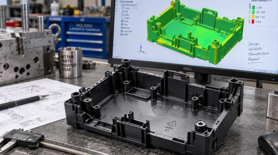
可制造性设计 (DFM) 检查壁厚、拔模斜度、倒扣、加强筋、凸台、分型线、浇口、排气孔和顶出。DFM 分析还应识别跨越分型线的尺寸以及需要滑块、升降器、嵌件、套筒或旋出机构的特征。
壁厚约为 1.5 至 2.5 毫米的部件适用于许多常见的热塑性塑料,但树脂供应商的产品范围和部件的功能是首要考虑因素。相邻壁的厚度应尽量接近。较厚的凸台底座冷却速度较慢,可能会导致对面出现明显的凹陷。拔模斜度有助于部件脱模;纹理表面通常比抛光表面需要更大的拔模斜度。
流动模拟可以测试浇口、流道平衡、熔接线、气穴、压力和热行为。它适用于薄壁、长流道、多腔模具和外观零件。每项发现都应指导相应的改进措施,例如移动浇口或修改冷却通道。
工具构建、试用和修正
CNC加工可形成大多数型芯和型腔。电火花加工可处理深槽、锋利的内部细节以及刀具无法精确加工的几何形状。线切割、研磨、装配和抛光等工序则可完成工具的最终加工。
T0 检查填充、开启、顶出和安全操作。团队记录短射、飞边、烧焦、缩痕、熔接线、翘曲、粘连和尺寸偏差。T1 样品应包含约定的树脂、工艺记录、尺寸报告和剩余步骤。即使是来自不稳定循环的漂亮样品,也仍然是未完成的结果。车间经常会吸取这样的教训。
哪些设计选择决定了零件质量?
零件质量取决于一系列相互关联的决策。浇口位置影响熔接线和包装。冷却影响循环时间和翘曲。顶出影响拖痕、泛白和变形。
闸门、冷却、排气和喷射
将浇口设置在熔体能够以可控压力填充型腔并压实较厚区域的位置。在多型腔模具中,平衡的流道至关重要,因为一个型腔过早填充会分散另一个型腔的压力。流道末端的排气孔可以排出滞留的空气,减少烧伤。
冷却通常占据注塑成型周期的大部分时间。型芯和型腔周围的冷却层需要均匀覆盖。局部过热会导致部分区域保持柔软,而邻近区域的塑料收缩,这可能导致脱模后扁平外壳发生扭曲。因此,顶针、顶套、脱料板、顶杆或气动顶出装置需要足够的接触面积,才能在不造成凹陷的情况下移动零件。
下单前应该检查哪些内容?
按范围比较报价。最低的模具费用报价意义不大,因为报价范围可能很广。mits树脂、试验、检验、变更或预期工具寿命。
实用采购清单
请各注塑模具制造商详细说明模具材料、硬度、型腔数量、流道类型、模具寿命、包含的试模次数、T1交货期、尺寸报告、维护计划和所有权条款。确认注塑机吨位和注射量。较大的注塑面积需要足够的锁模力来控制飞边。
比较不同数量的零件成本。冷流道适用于许多小批量生产,但每次注塑都会产生流道材料。热流道可以减少浪费,并可能缩短生产周期,但模具和维护成本更高。产量和树脂价格是选择流道的关键因素。
首次试模后,预留一次修正循环的时间。标准快速模具大约需要两到四周才能达到 T1 阶段。复杂的螺纹拆卸、嵌件或双材料结构可能需要四到八周。几何形状、钢材供应、表面处理和检验范围都可能导致交付日期变更,因此制定里程碑计划比一次性交付承诺更有用。
将原型结果转化为生产决策
试验报告应将每项缺陷与具体操作和责任人关联起来。这样的记录能将快速检测工具转化为切实可行的生产关卡。
XINKEY MOULD 通过早期可制造性设计 (DFM)、模流分析、快速原型模具开发、试模和过渡生产,为这一阶段提供支持。其工程范围涵盖滑块、顶杆、镶件、螺纹型芯、冷热流道、平衡顶出以及冷却布局,适用于需要比简单开合式模具更复杂功能的零件。精密加工包括数控加工 (CNC)、电火花加工 (EDM) 和线切割,加工控制精度可达 +/-0.01 毫米,具体取决于特征和检测方法。
团队可以将试验结果应用于模具修正和小批量零件生产,从而确保设计反馈、模具变更和工艺记录之间的关联性。对于采购方而言,这种连续性使得T1评审更易于审核,并为生产模具决策提供更可靠的成本和质量依据。
常问问题
问题1:快速原型模具生产T1样品的速度能有多快?
答:标准工具大约需要两到四周才能达到T1标准。滑块、旋出系统、嵌件、双材料结构、特殊钢材或要求高的表面处理可能会将工期延长至四到八周。
Q2:快速注塑模具一次可以生产多少个零件?
答:模具寿命取决于模具材料、树脂、压力、温度、几何形状和维护情况。报价前请确定所需的注塑次数,以便模具制造商选择合适的钢材并保护高磨损区域。
Q3:可以使用最终生产用的树脂吗?
答:是的,在很多项目中都是如此。使用指定的树脂能更好地检验其贴合性、强度、收缩率、热响应和表面质量。对于磨蚀性、腐蚀性或耐高温等级的树脂,可能需要使用钢制嵌件或钢制工具。
Q4:询价时需要发送哪些文件?
A:请提供 3D 模型、带尺寸标注的 2D 图纸、树脂等级、颜色、表面处理、数量、年度预测、关键公差、装配细节以及所需的样品日期。
Q5:何时应该过渡到生产模具?
答:当设计稳定、试验符合验收标准且预测产量支持使用长寿命模具时,即可考虑推进。决策时应参考原型运行中测得的周期时间、废品率、维护需求和单位成本。





联系我们