

5 Common Reasons TPE Peels Off PC + ABS Electronic Housings — and the Mold Fixes
-
 autor
- 29th October 2026
5 Common Reasons TPE Peels Off PC + ABS Electronic Housings — and the Mold Fixes
Why the bond fails at the interface, and which of those failures the tool can prevent
| Dealing with a TPE overmold that lifts at the edge? Faça o upload de arquivos CAD 3D para análise de DFM e orçamento de moldes. |
A TPE grip can pass first article and still peel six months into the field. The failure rarely starts at the surface. It starts a few micrometres into the interface, where the bond either formed, half-formed, or never formed at all.
All five causes below look identical on a customer complaint: a lifted edge on a housing. They have different fixes, and only some of them belong to the mold. This article covers the five failure modes we see most often on PC + ABS electronic housings with a TPE-S or SEBS overmold, what each one looks like in a peel test, and the tool-side changes that remove it before steel is cut.
Why Is PC + ABS a Difficult Substrate for TPE?
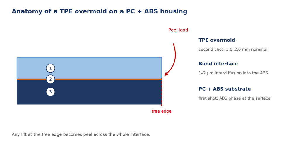
PC + ABS is a blend, not a single polymer. The ABS phase gives the surface enough chemical affinity for a TPE-S overmold to diffuse into it. The PC phase does not. Bond strength therefore depends on how much ABS sits at the surface where the second shot lands, and that fraction shifts with grade, flow history, and colour.
The second difficulty is thermal. PC + ABS needs a hot barrel and a hot tool. TPE-S needs a much lower melt temperature. The window in which the TPE arrives hot enough to diffuse into the substrate, but not so hot that it degrades the ABS phase, is narrow. Most of the five failures below are different ways of falling out of that window.
Figure 1. The bond is a 1–2 µm interdiffusion layer, not a glued surface. Load at the free edge stresses the whole interface.
The Five Failure Modes at a Glance
| Failure mode | What you see | What actually happened | Primary owner |
| 1. Interfacial contamination | Clean lift, glossy TPE underside | No bond formed | Process + tool |
| 2. Cold interface | Low peel strength, no visible defect | No interdiffusion | Tool + process |
| 3. Cold weld line | Peel starts at one point, then runs | Two fronts met and lost heat | Tool |
| 4. Sharp edge or thin wall | Lift begins at the TPE boundary | Stress concentration at the edge | Tool |
| 5. No mechanical interlock | Passes the peel test, fails in use | Adhesion carrying peel load | Tool + design |
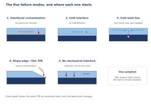
Figure 2. Five different weak points, one identical symptom.
Reason 1: The Bonding Surface Was Contaminated
What it looks like. The TPE lifts as a clean sheet. The underside is glossy, and the substrate shows no trace of polymer pulled away. That detail tells you which failure you have. A cohesive failure, where material tears on one side, means the bond was stronger than the material. An adhesive failure, with a clean interface, means there was no bond to break.
Why it happens. Mold release agent from the first shot, silicone from an adjacent process, cutting oil, dust from storage, or skin oil from manual insert loading all sit between the two melts. Gas does the same thing. An unvented first-shot cavity leaves a deposit in the bonding area that behaves like a release film. So does a hot insert that has been sitting and outgassing.
Mold fix. Remove external release agent from the first-shot tool and rely on draft and ejection instead. Vent the first-shot cavity at the last-fill point so gas leaves rather than plating out on the bonding surface. Keep ejector pins and lubrication points out of the bond area. Then write the handling rule into the work instruction: gloves, no stacking of freshly molded inserts, and a maximum dwell time before the second shot.
Reason 2: The Substrate Was Too Cold When the TPE Arrived
What it looks like. Peel strength is low, but the failure does not look contaminated. Under a microscope the interface shows little or no interdiffusion. The TPE sat on the surface instead of dissolving into it.
Why it happens. Bonding between TPE-S and the ABS phase is diffusion, and diffusion needs the substrate surface above its softening range. A first-shot insert that cools on a tray, a rotary tool whose second station runs colder than the first, or a thick metal insert acting as a heat sink will all drop the surface below that range before the TPE arrives.
Mold fix. Control the second station independently: separate temperature zones on the core and cavity side, and a controlled insert pocket instead of a bare steel seat. Where the geometry allows, insulate the insert seat to slow heat loss. Size the runner and gate so the melt reaches the bonding area hot, and confirm it in the flow simulation by reading melt temperature at the interface, not just at the gate.
Reason 3: A Cold Weld Line Formed in the Bond Area
What it looks like. Peel starts at one point and then runs along the boundary. The starting point is usually opposite the gate, behind a boss, or between two pins. A visible line often crosses the TPE at the same spot.
Why it happens. Any core, boss, hole, or rib in the TPE cavity splits the flow. When the streams rejoin, both fronts have already lost heat and picked up air. Two cold fronts meeting form a weld line with weak bonding to the substrate, and if the gas has nowhere to go, a burn or a short shot at the same location.
Mold fix. Move the gate so the flow front reaches the bonding area as a single front. Add vents at the last-fill point, and overflows where venting is not possible. Use the flow simulation to plot weld-line position and air traps on top of the bonding area. If a weld line lands inside it, change the gate before cutting steel.
Reason 4: The Edge Geometry Starts the Peel
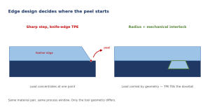
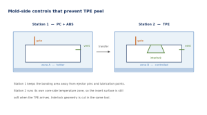
Figure 3. A feather edge concentrates load at a single point. A dovetail moves that load into the geometry.
What it looks like. The lift begins at the boundary between TPE and exposed substrate, usually within the first few millimetres. The bond area itself is intact, which is why a peel test cut from the middle of the part can pass while the housing still fails in the field.
Why it happens. A sharp step, or a feather edge thinner than about 0.5 mm, is a stress concentrator. Under any peel or thermal load the stress at the tip is many times the nominal value, so a bond that is strong enough in the middle fails at the edge. Thin TPE sections make it worse. Below roughly 1 mm the melt loses heat quickly, packing is poor, and the bond at the edge becomes the weakest in the part.
Mold fix. Radius the transition and hold the TPE section at a thickness the material can fill and pack. 1.0 to 2.0 mm is a workable starting range, confirmed against the flow simulation. Where the design allows, move the parting line away from the sealing edge so flash or mismatch does not sit on the boundary that starts the peel.
Reason 5: Adhesion Is Carrying Load It Was Never Designed to Carry
What it looks like. The part passes the peel test and fails in use. After drop, after thermal cycling, after a screw boss is tightened, or after cleaning with a solvent.
Why it happens. TPE expands several times more than PC + ABS over the same temperature range. Every thermal cycle puts the interface in shear, and every assembly step adds a peel component at the edge. Adhesion alone has no answer to repeated shear. A mechanical lock does.
Mold fix. Build the interlock into the tool: through-holes the TPE fills, dovetail or T-slot grooves, undercuts on the substrate, or a tongue-and-groove at the boundary. These are mold features, not material changes, and they are only free if they were designed in. The rule is simple. The bond seals, and the geometry holds.
What the Mold Can Fix, and What the Process Still Owns
Buyers often ask for a tooling change to solve a process problem. The table below separates the two, so the fix lands on the right side of the purchase order.
| Failure mode | Tool-side action | Still required in production |
| 1. Interfacial contamination | Vent the first-shot cavity at last fill; keep ejectors and grease points out of the bond area | Clean inserts, gloves, no external release agent |
| 2. Cold interface | Independent second-station temperature zone; controlled insert pocket | Transfer time, insert preheat, machine settings |
| 3. Cold weld line | Gate position, vent and overflow layout | Verified shot parameters, regrind control |
| 4. Sharp edge | Radius, wall thickness, parting-line placement | Fill and pack profile confirmed on the press |
| 5. No interlock | Through-holes, dovetails, undercuts | Assembly and handling designed not to peel the edge |
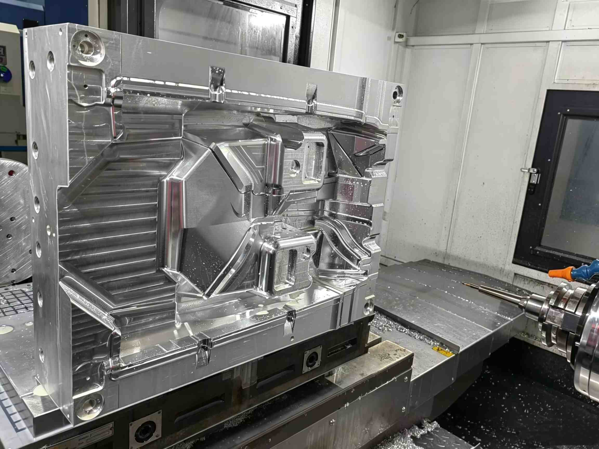
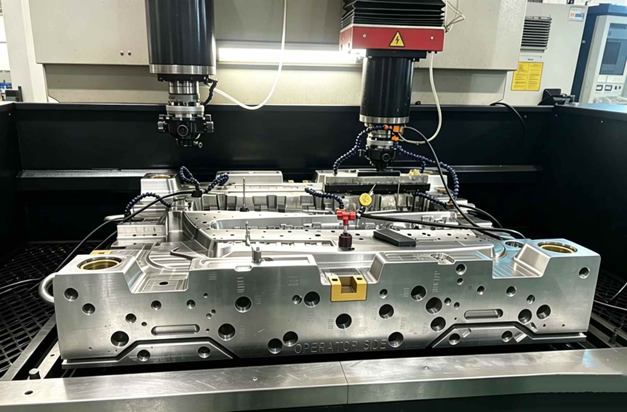
Figure 4. Gate, vent, per-station temperature and interlock: all decided before steel cutting.
XINKEY MOULD reviews these five modes as part of DFM, before tooling starts. That covers wall and edge geometry, gate and vent layout, per-station temperature zoning, and interlock features for TPE overmolds. Capability covers ±0.01 mm-level CNC machining, injection presses from 90T to 750T, and 2K tooling on a rotary table. Those figures describe company capability, not measured results for any specific housing.
How Should You Validate the Fix Before Mass Production?
A peel test that only reports force will hide the difference between the five modes. Record the failure type as well: adhesive, cohesive, or mixed. A cohesive break at high force is a good bond. A mixed break at the edge points to geometry. An adhesive break at low force points to contamination or a cold interface.
Run the test on parts from the first 100 shots, then repeat it after a thermal cycle. Section the edge and look at the interface under a microscope, where the interdiffusion layer is visible or it is not. Then repeat the peel after assembly and after cleaning with the solvent your customer will actually use.
Buyer Checklist for a TPE Overmold Project
- Both resin grades, including the ABS fraction and any flame retardant in the PC + ABS
- The TPE grade and hardness, and whether the bond is adhesion-only or mechanically locked
- 3D model and 2D drawing with the TPE wall thickness and edge geometry called out
- Cosmetic and sealing requirements at the TPE boundary
- Annual volume, expected mold life, and cavity target
- Peel acceptance criteria: force, failure mode, and test method
- Cleaning solvents and assembly loads the housing will see in service
Perguntas frequentes
Why does TPE peel off PC + ABS but bond well to PP?
Polypropylene and TPE-S are both olefinic, so the interface diffuses easily. PC + ABS is a blend. Only the ABS phase is compatible with TPE-S, and the PC phase is not. Bond strength therefore depends on the ABS fraction at the surface, which is why two suppliers’ PC + ABS can behave differently in the same tool.
Can changing the TPE grade fix peeling?
Sometimes. A grade formulated for polar substrates will bond better to the ABS phase than a general-purpose grade. But if the failure is contamination, a cold interface, a weld line, or a sharp edge, a new grade only moves the failure point. Diagnose the mode first, then change material.
Does plasma or flame treatment help?
Both raise surface energy and improve wetting, and both are used in production. They also add a process step that has to be controlled and monitored, and they do not fix a weld line or a stress concentration. Treat them as a complement to tool geometry, not a replacement.
How thick should the TPE be?
Thick enough to fill and pack, thin enough to stay flexible. 1.0 to 2.0 mm covers most grips and seals. Below about 0.5 mm at the edge, the material cools before it can bond, and the edge becomes the peel initiation point.
Can peeling be fixed in an existing mold?
Partly. Gate position, venting, and temperature zoning can often be changed. Adding an interlock or a radius usually means cutting new steel, and sometimes a new insert. That is why the five modes are worth reviewing during DFM, before the first cut.
Request a DFM Review and Quote
Have a TPE overmold that lifts at the edge, or a housing about to go into tooling? Upload your 3D CAD files, both resin grades, annual volume, and the cleaning and assembly conditions the part will see through the Free Quote pageA página de serviços aceita arquivos STEP, STP, IGES, IGS, XT, DWG, PDF e ZIP de até 30 MB. Para contato direto, utilize o Página de Contato ou envie um e-mail para Contact-Xinkey@xinkeymould.com.




Contacte-nos