The Art of the Parting Line: Why Mold Design is More Than Just Splitting a Part
-
 autore
- 17th March 2026
In the world of injection molding, the parting line is never just a random “split.” It is the high-stakes intersection where engineering constraints meet aesthetic demands. A well-designed parting surface isn’t just functional—it’s elegant, easy to machine, and built for a million-cycle lifespan.
Getting it right requires a blend of cold engineering logic and years of “boots-on-the-ground” shop experience.
First, a Quick Refresher:
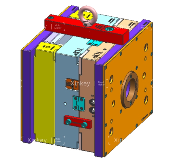
- The Parting Surface: This is the “handshake” between the A-side (cavity) and B-side (core). It’s the primary interface that defines the tool’s geometry.
- The Parting Line: This is the witness mark left on the final part. To an engineer, it’s a map of how the mold functioned; to a consumer, it should be as invisible as possible.
Our philosophy is simple: Optimize for demolding, simplify for machining, and design for and keep a sharp eye on the total cost of ownership.
Here is how we break down the parting line strategy.
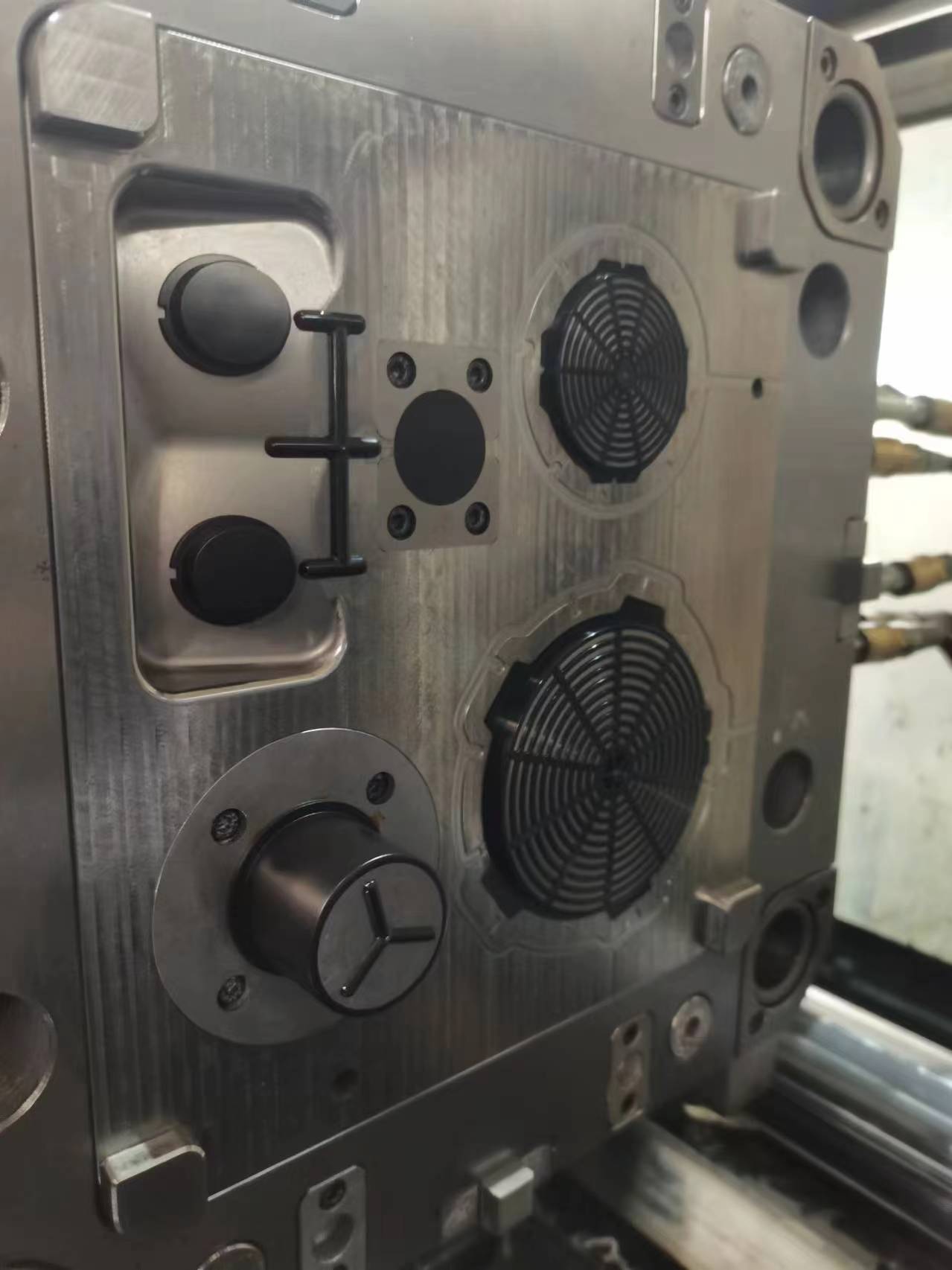
- Aesthetics & Precision: “The Invisible Witness”
In a perfect world, the parting line should be invisible. If the end user can catch a ridge with their fingernail or see a distracting flash, we’ve missed the mark on the DFM.
- Bury the Mark: We keep parting lines off primary cosmetic surfaces. We prioritize hiding them in transitions, ribs, or decorative grooves. When hiding the line isn’t an option, we’ll often bake a decorative step or a “shadow line” into the design to camouflage the mismatch.
- Concentrate Precision Features: Don’t split high-tolerance geometry—like mating steps or concentric bores—across both halves. Keep them on one side to avoid the inevitable headache of mold shift and tolerance stack-up.
Splitting them across the parting line introduces assembly errors and concentricity headaches.
- Protect Functional Zones: Never run a parting line through a sealing surface or a precision thread. It’s a recipe for leaks and mechanical failure.
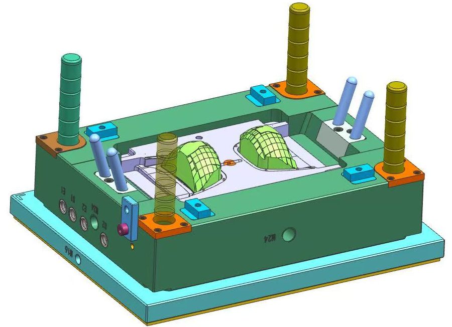
- The Demolding Priority: “The Clean Release”
A part that hangs up in the tool is more than a nuisance—it’s a production disaster..
- Hunt for the Widest Profile: We always split the mold at the part’s maximum cross-section. This ensures the part clears the steel without interference.
- Ensuring the B-Side “Hug”: Since the ejection hardware lives on the moving half, the part needs to stay there when the mold cracks open. We pull this off by carefully balancing the draft and texture—intentionally making the part “grab” the core so it clears the cavity every single time.
- Kill the Slides: Side-actions (sliders and lifters) add cost and complexity. We always look for ways to tweak the parting line to eliminate the need for side-pulls. If we must use them, we keep the travel distance short and the action on the B-side.
- Manufacturability: “The Breathable Mold”
A mold that can’t breathe will fail. We use the parting line as the tool’s lungs.
- Natural Venting: We strategically place the parting line at the end of the melt flow. This allows trapped air to escape naturally, preventing the dreaded “dieseling” or gas burns that ruin parts.
- Managing Thin Geometry: Fighting wall thickness variation in thin parts often requires switching to a conical or interlocking “stepped” parting plane. This locks the tool geometry in place, keeping the nominal wall consistent and fighting the urge for the part to potato-chip (warp) during cooldown.
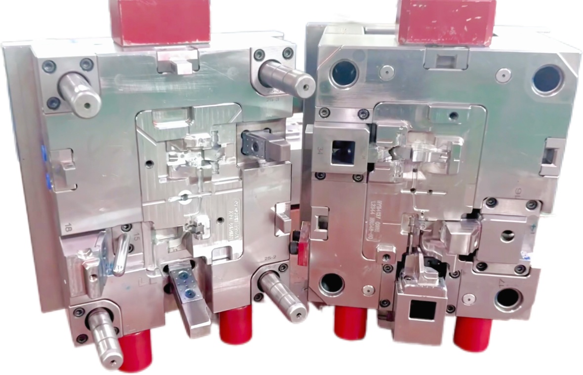
- Tooling & CNC: Keep it Machinable
Complexity is the enemy of the mold maker.
- Avoid the “Rollercoaster”: Whenever possible, we use flat parting planes. Twisted, multi-level parting surfaces might look cool in CAD, but they are a nightmare to CNC and even worse to “spot” (hand-fit) during assembly.
- No “Thin Steel” Conditions: We avoid sharp corners or thin blades of steel near the parting line. These areas are prone to “chipping” or early wear, leading to flash and expensive repairs down the road.
- Economics: “Fighting the Press”
The way we split the part directly affects the cost per piece.
- Minimize the Footprint: We align the parting line to minimize the part’s projected area relative to the clamping direction. Lower projected area means lower required tonnage—meaning we can run your part on a smaller, cheaper press.
- Standardize and Simplify: One main parting line is always better than three. The simpler the tool, the lower the maintenance cost and the higher the reliability.
The Bottom
At the end of the day, a parting line isn’t just a mark on a part—it’s a signature of the engineering quality behind it. Whether you are looking for medical-grade precision or high-volume consumer goods, how you split your mold defines your success.


Contattaci