
Diseño de deslizadores para moldes de inyección: estructura, función y mejores prácticas
-
 autor
autor
- 25 de abril de 2026
Introducción
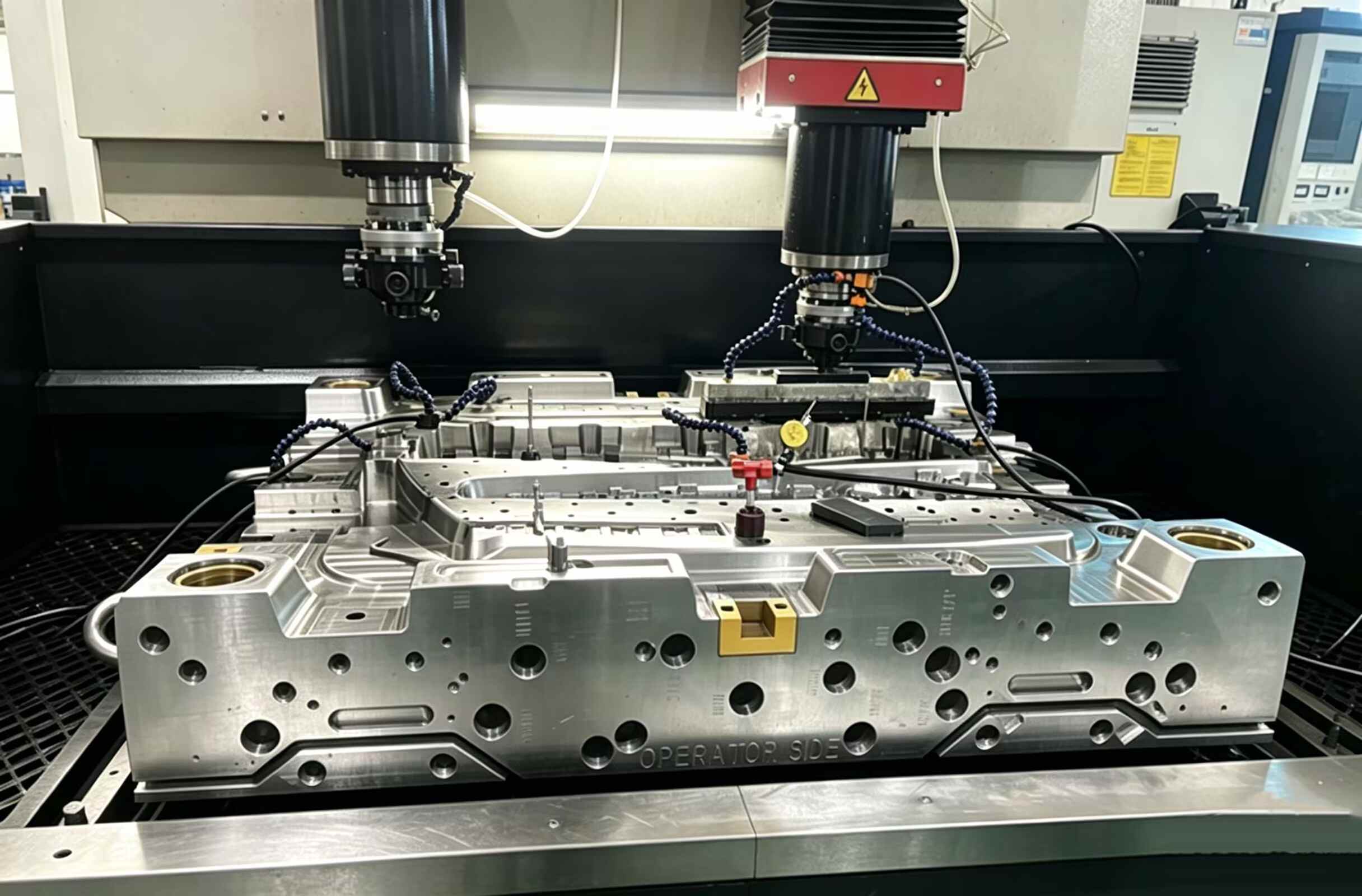
Los deslizadores (también llamados actuadores laterales o núcleos laterales) son componentes del molde que se mueven perpendicularmente —o en ángulo— a la dirección de apertura del molde. Se utilizan para formar y liberar socavaduras externas que, de otro modo, impedirían la eyección directa. Para los ingenieros de moldes que trabajan con piezas de plástico complejas, comprender el diseño de los deslizadores es fundamental.
¿Qué es un deslizador de moldes?
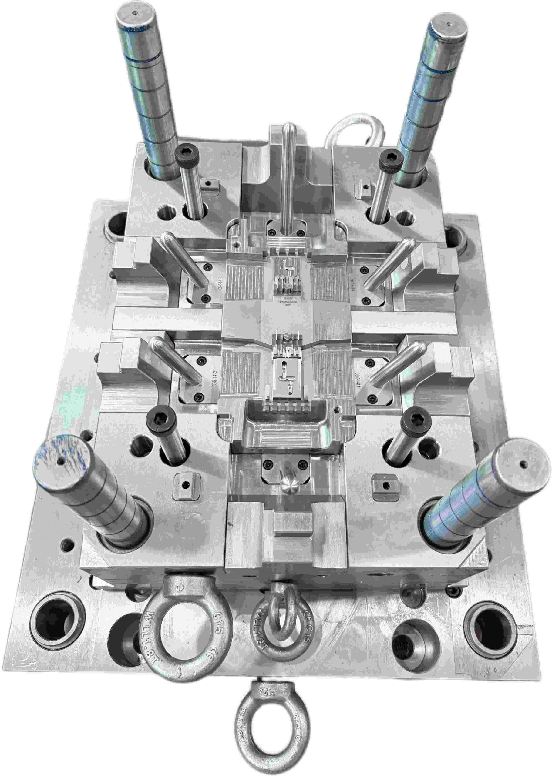
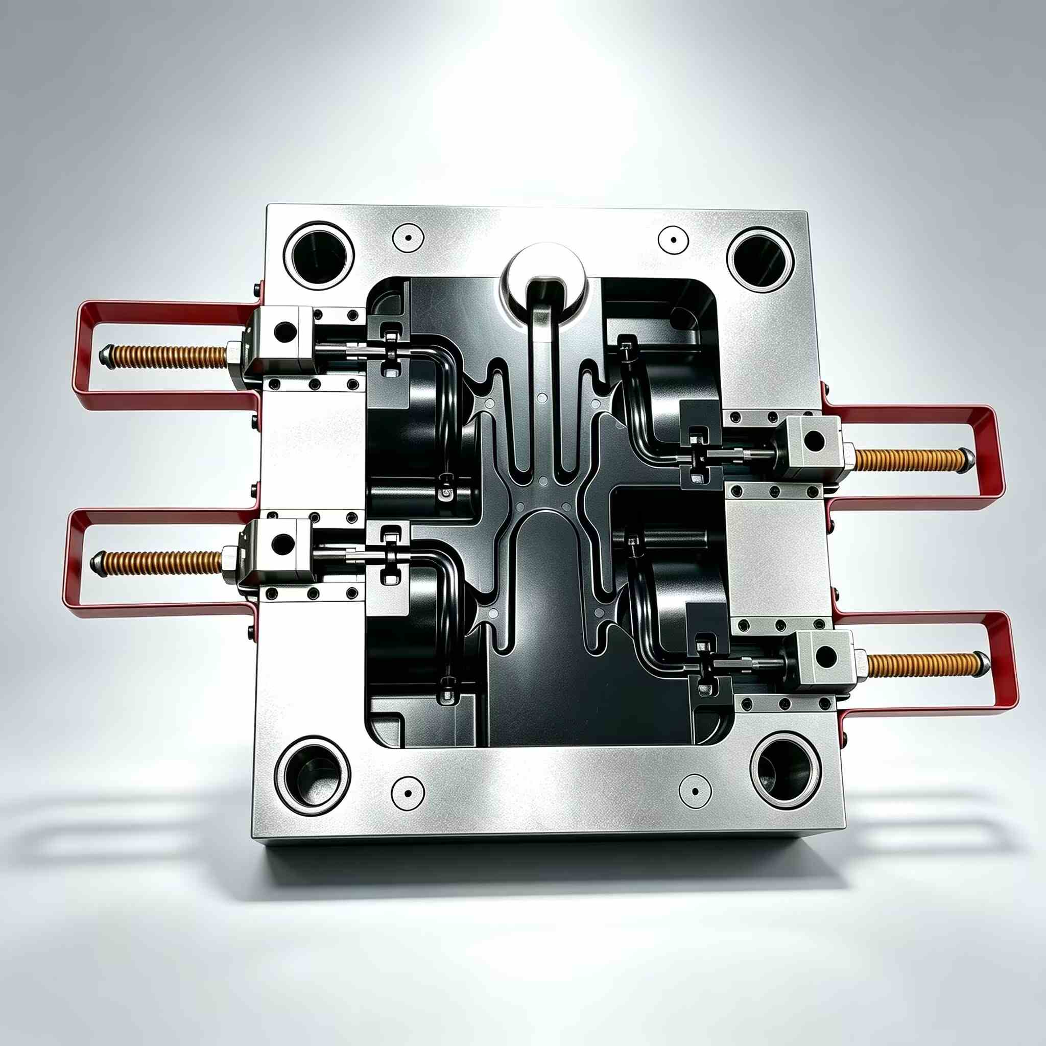
Un deslizador es un componente móvil del molde que se desplaza lateralmente durante la carrera de apertura para liberar las socavaduras externas de la pieza moldeada. Generalmente, se acciona mediante un pasador angular (también llamado pasador de leva o pasador de cuerno) montado en la mitad fija del molde.
Al abrirse el molde, el pasador angular empuja el deslizador hacia afuera. Durante el cierre del molde, el deslizador regresa a su posición de trabajo, listo para el siguiente ciclo.
Para garantizar la estabilidad durante la inyección, el deslizador se bloquea mediante un tope (cuña de bloqueo). Sin este soporte, la alta presión en la cavidad —que a menudo alcanza cientos de toneladas— puede desplazar el deslizador, provocando rebabas o variaciones dimensionales.
Para la construcción de moldes estándar, se suelen utilizar aceros para herramientas pretemplados, como el P20, para el cuerpo del deslizador. Sin embargo, en aplicaciones de mayor volumen, el P20 por sí solo no es suficiente. A menudo se añaden insertos endurecidos o placas de desgaste en las zonas de mayor contacto para reducir la fricción, mejorar la resistencia al desgaste y prolongar significativamente la vida útil de la herramienta.
El deslizador se guía mediante guías o pilares de guía para mantener la alineación durante todo su recorrido. La distancia de recorrido debe ser al menos igual a la profundidad de socavado más un margen de seguridad de 2 a 3 mm.
¿Por qué son necesarios los controles deslizantes?
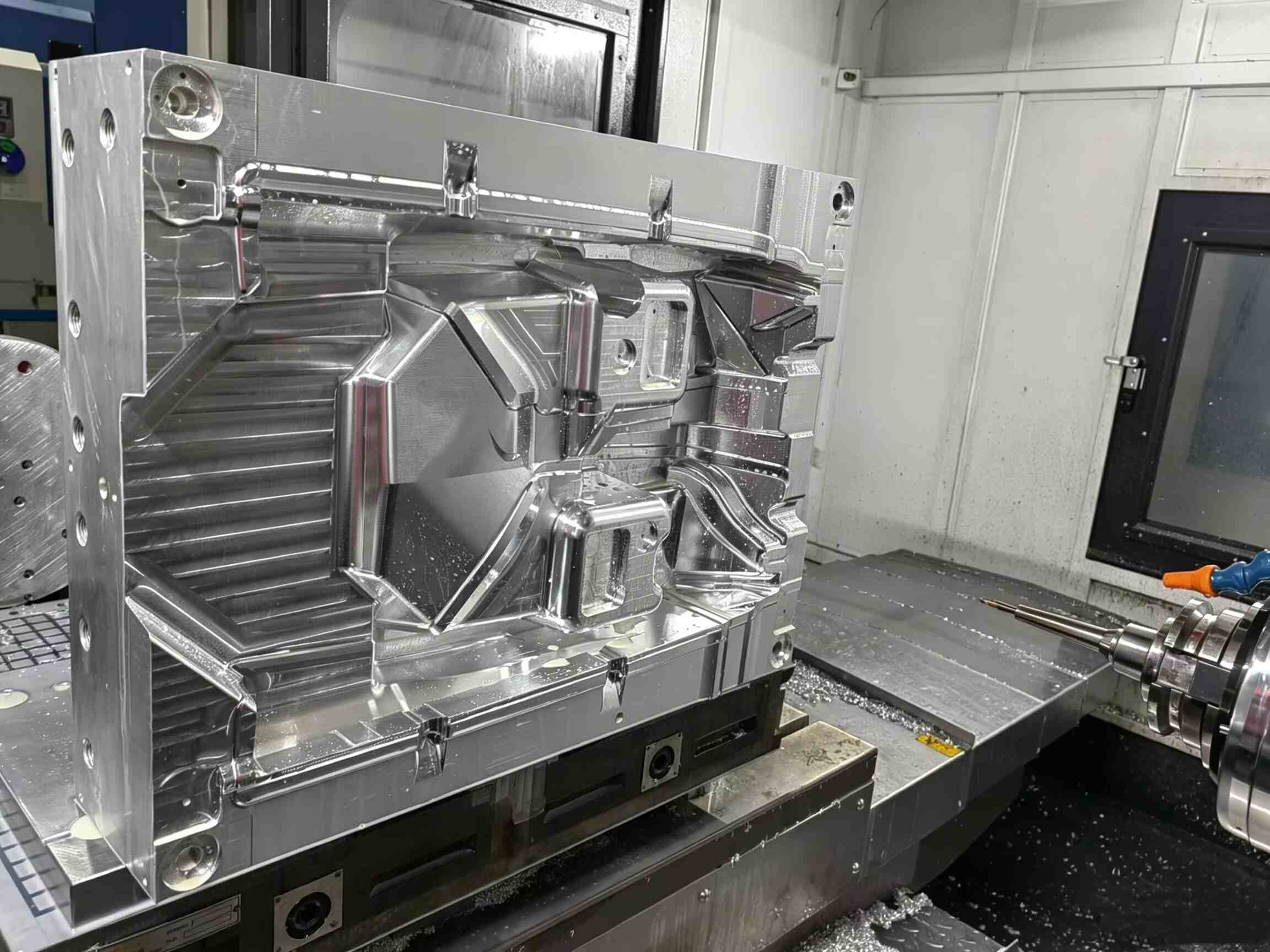
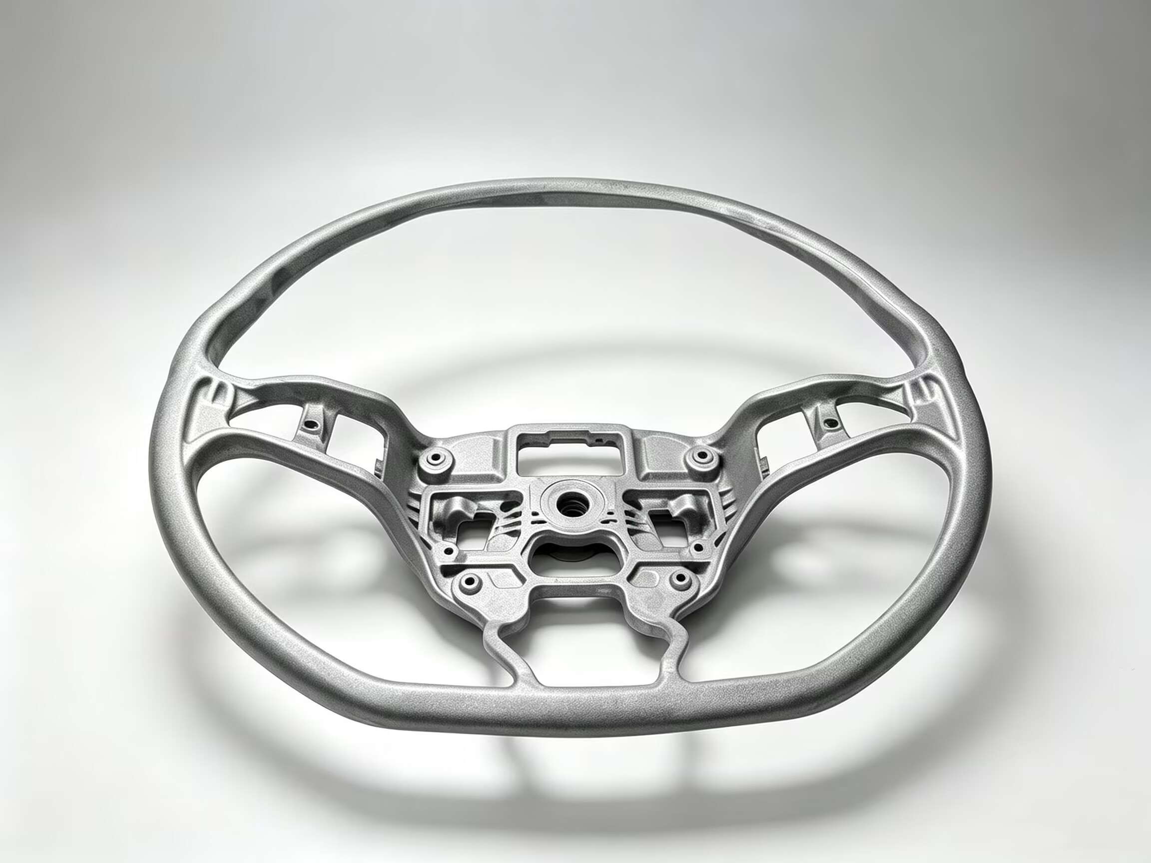
Muchas piezas de plástico incluyen características como orificios laterales, roscas, ganchos, clips o geometrías rebajadas en las superficies externas. Estas características crean socavados que impiden la expulsión en línea recta del molde.
Sin un sistema de accionamiento lateral, como un deslizador, la pieza quedaría bloqueada mecánicamente en la cavidad. Cualquier intento de expulsarla directamente conllevaría el riesgo de dañar la pieza, desgastar el molde o incluso detener la producción.
En la práctica, el deslizador actúa como un mecanismo de liberación obligatorio: debe retraerse por completo antes de que se active el sistema de expulsión. Si la sincronización es incorrecta, la pieza puede quedar atrapada, lo que podría ocasionar daños y tiempos de inactividad no planificados.
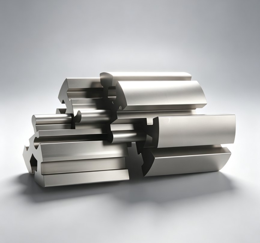
En comparación con los elevadores internos, los deslizadores suelen ser más robustos para socavados externos. Se accionan mediante el movimiento de apertura del molde y se bloquean mecánicamente contra la presión de inyección mediante el bloque de talón, lo que los hace adecuados para entornos de producción de alto volumen donde se requieren millones de ciclos.
Una ventaja clave de los deslizadores es su capacidad de distribución de carga. El bloque del talón y las superficies de guía distribuyen las fuerzas de inyección sobre una mayor superficie de contacto, lo que reduce la deflexión y el desgaste en comparación con los sistemas de elevación mecánicos más pequeños.
Problemas comunes con los controles deslizantes
1. Dolor y convulsión
El desgaste por fricción en las superficies deslizantes se produce cuando estas operan con lubricación insuficiente, lo que provoca la acumulación de metal y, finalmente, el agarrotamiento. Esto es especialmente común en moldes que utilizan materiales abrasivos como el nailon reforzado con fibra de vidrio o el polipropileno reforzado con minerales. Una vez que comienza el desgaste por fricción, tiende a acelerarse rápidamente y, en última instancia, puede provocar el bloqueo de las superficies deslizantes y el desmontaje del molde para su reparación.
2. Carga excesiva en el pasador angular
Cuando el ángulo de inclinación supera aproximadamente los 25°, la carga lateral aumenta significativamente. Esto acelera el desgaste de las guías, los bloques de talón y el propio ángulo de inclinación.
Los ángulos más pronunciados también aumentan la fuerza necesaria durante la apertura del molde, lo que ejerce una tensión adicional sobre todo el mecanismo con el tiempo.
3. Flash en superficies apagadas
La aparición de un destello en la superficie de cierre del deslizador indica un asentamiento incorrecto. Las causas comunes incluyen tacos de talón desgastados, precarga insuficiente o una ligera deformación del pasador angular.
Si no se soluciona a tiempo, la acumulación de rebabas puede acelerar el desgaste tanto del deslizador como de las superficies de contacto.
4. Desalineación temporal
Una sincronización incorrecta del deslizador puede provocar defectos graves. Si el deslizador se mueve antes de que la pieza se haya liberado por completo, puede arrastrarla lateralmente, lo que provoca rozaduras en la superficie, deformaciones o distorsiones dimensionales.
Soluciones de diseño y mejores prácticas
- Mantenga la geometría del pasador angular entre 15° y 22° para equilibrar las fuerzas y reducir la carga lateral.
- Mecaniza ranuras de lubricación específicas en las placas de desgaste y asegúrate de que la grasa llegue a todas las superficies de deslizamiento.
- Utilice materiales autolubricantes como Casquillos de bronce AMPCO, bujes Oilite o insertos de desgaste de material compuesto..
- Implementar un sistema de retorno con resorte para garantizar el asentamiento completo del deslizador antes del cierre del molde.
- Ángulos de bloqueo del bloque del talón de diseño 2–3° más inclinado que el pasador angular para garantizar un cierre seguro bajo presión.
- Agregar un sistema de retorno del eyector temprano De esta forma, los pasadores eyectores se retraen antes del movimiento del deslizador para evitar interferencias mecánicas.
Consejo profesional
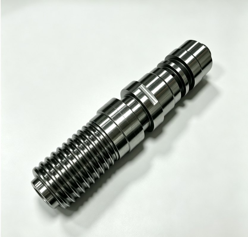
Un deslizador bien diseñado debe sentirse como un mecanismo de precisión: suave en su movimiento, firme al bloquearse y consistente desde el primer disparo hasta el último.
Un buen rendimiento rara vez se basa en la complejidad. Proviene de aspectos fundamentales: seleccionar los materiales de desgaste adecuados, garantizar una lubricación correcta y diseñar un sistema de retorno mecánico fiable. Cuando estos aspectos básicos son correctos, el molde funciona con una intervención mínima.
Sin embargo, el deslizador más rentable suele ser el que nunca se fabrica. Siempre evalúe si un pequeño cambio en el diseño de la pieza puede eliminar por completo el socavado. Simplificar la geometría generalmente conlleva un menor costo, una mayor fiabilidad y un mantenimiento más sencillo.


Contacta con nosotros