
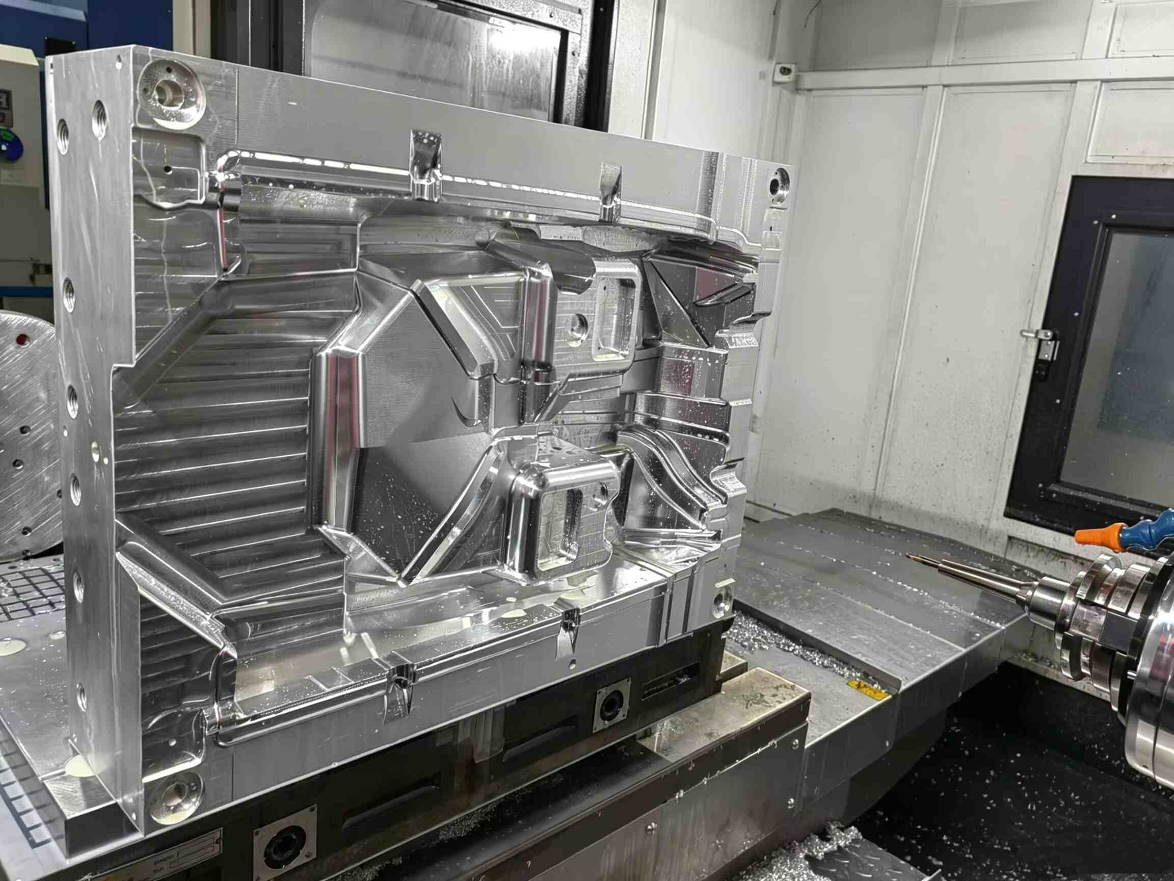
لماذا تُعدّ التجاويف الداخلية مشكلة خطيرة في قولبة الحقن؟
-
 أرونا تشنغ
- 15 أبريل 2026
لنكن صريحين: التجاويف الداخلية تشكل كابوساً لمصممي القوالب. على عكس الميزات الخارجية، لا يمكن التعامل معها باستخدام المنزلقات القياسية.
إذا لم يتم تصميم الشكل الهندسي بشكل صحيح، فإن العواقب ستكون وخيمة:
- أجزاء عالقة بشكل دائم على القلب
- تلف السطح أو الخدوش
- انكسار قضيب الرافعة
- توقف الإنتاج المكلف
عند التعامل مع المقاطع الداخلية أو الرؤساء، رافعة القوالب يصبح الحل الميكانيكي الأكثر موثوقية.
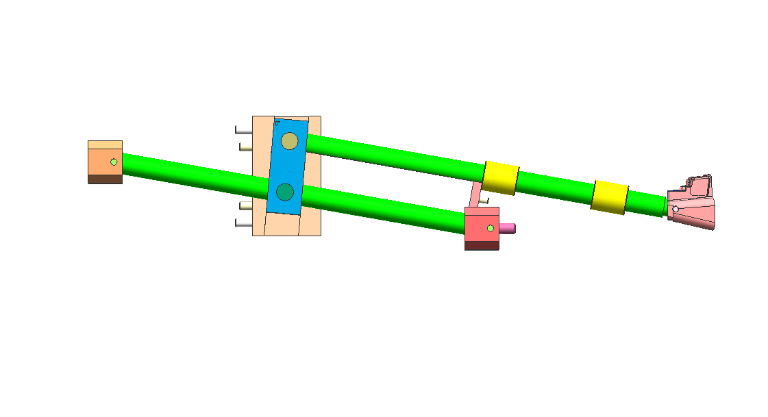
كيف يعمل رافع القوالب: مبدأ "الخطوة الجانبية"
لا يتحرك رافع القالب مثل المنزلق التقليدي. بدلاً من ذلك، يتم تشغيله بواسطة نظام القذف.
أثناء دورة القذف:
- يتحرك الرافعة للأعلى مع لوحة القذف
- وفي الوقت نفسه، يتبع ذلك مسار مائل
- وهذا ينتج عنه مزيج الحركة الرأسية والجانبية
هذه الحركة الجانبية - والتي تسمى غالبًا "التحرك الجانبي"هذا ما يُحرر الجزء السفلي من الشعر.
قاعدة التصميم الرئيسية
اسمح دائمًا مسافة حركة إضافية لا تقل عن 2 مم أبعد من عمق القطع السفلي.
أي شيء أقل من ذلك يزيد من خطر:
- علامات السحب
- خدوش سطحية
- إصدار غير مكتمل
الخطأ الأكثر شيوعًا: زاوية الرافعة غير الصحيحة
من أكبر أخطاء التصميم هو جعل زاوية الرافعة شديدة الانحدار لتوفير المساحة.
زاوية الرافعة الموصى بها
- النطاق الأمثل: 5° – 11°
منطقة خطرة
- فوق 15 درجة مئوية: خطر كبير للالتصاق والفشل
عند الزوايا الأكثر حدة:
- تزداد القوة الجانبية بشكل ملحوظ
- تصبح الحركة الرأسية مقيدة
- قد يتعطل الرافعة أو قد ينثني القضيب
عندما تكون الزوايا الحادة أمراً لا مفر منه
إذا كان تصميمك يفرض زاوية أكبر، فضع في اعتبارك ما يلي:
- قاعدة رافعة مفصلية
- تصميم رافعة على شكل حرف T
تساعد هذه العوامل على تقليل الضغط على قضيب الرافعة وتحسين المتانة.
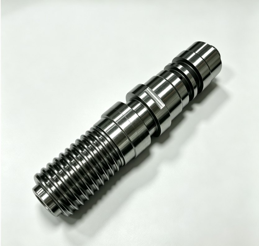
اختيار المواد: منع التآكل والاهتراء
تعمل أنظمة الرفع وفقًا لما يلي:
- ضغط عالٍ
- درجة حرارة عالية
- التلامس المعدني المستمر
قد يؤدي اختيار المادة الخاطئة إلى أمرٌ مُثيرٌ للغضب، حيث تلتحم الأسطح ببعضها وتفشل.
المواد الموصى بها
- فولاذ الأدوات H13
- فولاذ 718H مُقسّى مسبقًا
دليل الصلابة
- هدف: 50-54 HRC
- حافظ على قوة عضلات الرافعة أعلى قليلاً من قوة عضلات الجذع.
خيار عالي الأداء
للحصول على أوقات دورة أسرع:
- يستخدم حشوات من نحاس البريليوم
فوائد:
- تبديد أسرع للحرارة
- تقليل وقت التبريد
- زيادة كفاءة الإنتاج
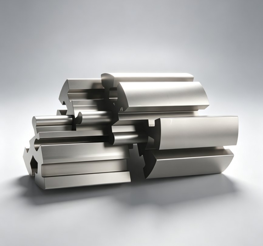
3 نصائح من الخبراء لتصميم رافعة مضادة للرصاص
1. إضافة دليل "الذيل"
احرص دائمًا على دعم الجزء السفلي من قضيب الرافعة باستخدام كتلة توجيه.
بدون دعم:
- يهتز القضيب
- يؤدي الاهتزاز إلى الوميض والتآكل
2. استخدم أخاديد الزيت
الاحتكاك هو عدو أي مكون متحرك.
أفضل الممارسات:
- أضف أخاديد تشحيم إلى الأسطح المنزلقة
استثناء:
- القوالب الطبية ← استخدم طلاء DLC بدلاً من الزيت
3. التحكم في خط الفصل (PL)
يجب أن يتطابق سطح إغلاق الرافعة تمامًا مع القلب.
حتى فجوة 0.01 مم قد يسبب ما يلي:
- خطوط شهود مرئية
- جودة سطح رديئة
الرافعة مقابل المنزلق: أيهما يجب أن تستخدم؟
يعتمد الاختيار بين الرافعة والمنزلق كلياً على موقع القطع السفلي.
استخدم شريط التمرير عندما:
- القطع السفلي خارجي
- توجد مساحة كافية للمناورة الجانبية
استخدم الرافعة عندما:
- القطع السفلي داخلي
- المساحة محدودة
- الأنظمة الهيدروليكية غير عملية
الخاتمة
تعتبر رافعة القوالب واحدة من أكثر الحلول فعالية للتجاويف الداخلية - ولكن فقط عند تصميمها بشكل صحيح.
من خلال التحكم في:
- زاوية
- تصريح السفر
- اختيار المواد
- الدعم الهيكلي
يمكنك تحويل ميزة عالية المخاطر إلى آلية موثوقة وقابلة للتكرار وهذا ما يضمن استمرار خط الإنتاج بسلاسة.
هل تحتاج إلى مساعدة في تحسين تصميم القالب أو حل مشكلة التجاويف المعقدة؟
يزور www.xinkeymould.com للحصول على دعم الخبراء وتحسين أداء أدواتك.


اتصل بنا