

Oltre l'onda: come eliminare i segni di flusso e preservare la finitura della superficie
-
 autore
- 18 maggio 2026
Segni di flusso nello stampaggio a iniezione | Cause, risoluzione dei problemi e metodi di prevenzione per migliorare la qualità estetica dei componenti
Siamo onesti: niente rovina una produzione più velocemente dei segni di flusso.
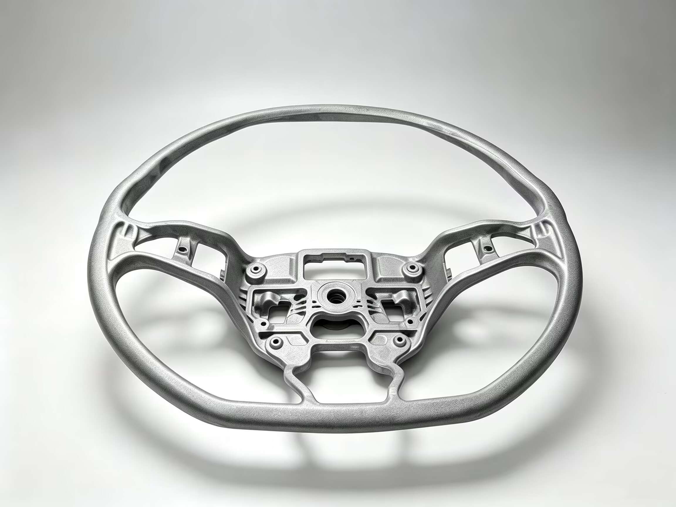
Si può avere un componente che rispetta tutte le specifiche dimensionali e si adatta perfettamente, ma se la superficie è ricoperta di linee ondulate o striature antiestetiche, finirà dritto nel cestino degli scarti. In settori come quello automobilistico o dell'elettronica di consumo, dove l'aspetto estetico è fondamentale, questi motivi fantasmatici sono un vero e proprio difetto inaccettabile.
La parte più frustrante? I segni di flusso sono solitamente puramente estetici. Il pezzo è strutturalmente integro, eppure agli occhi del cliente viene comunque considerato un "prodotto da scartare". Se sei stanco di vedere i tuoi margini di profitto svanire in un mucchio di scarti estetici, devi capire esattamente perché il fronte di fusione ha difficoltà all'interno dello stampo.
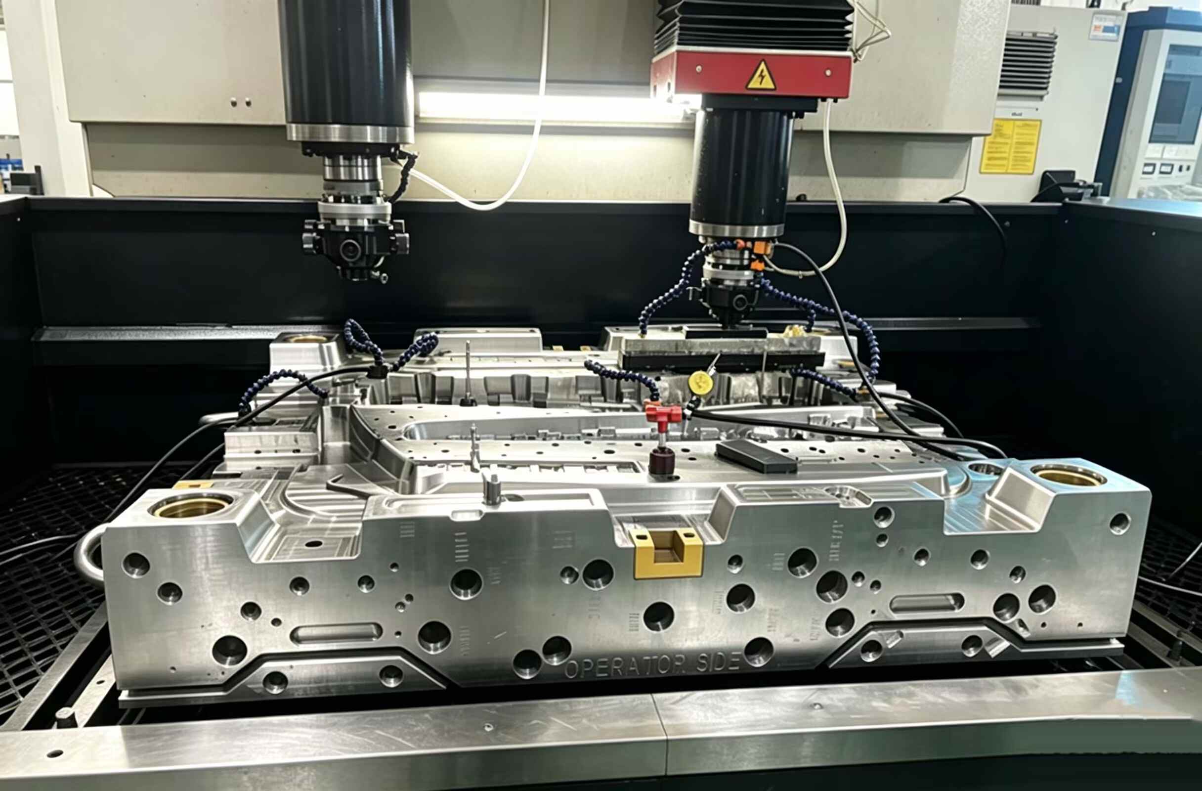
Cosa succede realmente all'interno della cavità?
In sostanza, un segno di flusso è una registrazione permanente di un fronte di fusione "esitante".
Pensate al fronte di fusione quando colpisce l'utensile: quello strato esterno è in una corsa costante contro l'acciaio freddo dello stampo. Se il flusso è troppo lento o il calore non è sufficiente a supportarlo, quel bordo anteriore non scorrerà, ma si fermerà.
Quando la resina più calda che si trova dietro finalmente avanza, lascia una cicatrice permanente sulla superficie. Quella linea ondulata o quel disegno ad anello che vedi è essenzialmente una mappa visiva di un flusso che ha lottato per ogni centimetro.
Non si tratta solo di un difetto estetico; è una prova inconfutabile che dimostra come il materiale stia soccombendo alla temperatura dell'utensile.
Secondo la nostra esperienza, questi segni si riscontrano quasi sempre negli stessi pochi punti critici.
Posizioni comuni dei segni di flusso
Nella maggior parte dei casi, i segni di flusso compaiono in prossimità di:
- aree di accesso
- Transizioni da parete sottile a parete spessa
- angoli acuti
- Percorsi di flusso lunghi
- Zone con improvvisi cambiamenti di direzione del flusso
Che aspetto possono avere i segni di flusso
A seconda del materiale e della struttura dello stampo, il difetto può presentarsi come segue:
- Linee ondulate
- Anelli Halo
- Striature simili a serpenti
- differenze di gloss
- segni d'ombra
Sulle parti lucide o di colore scuro, i segni di flusso sono generalmente più facili da notare.
Perché si formano i segni di flusso?
Nel processo di pressatura, tutto dipende da un delicato equilibrio tra il flusso del materiale fuso e il raffreddamento dello stampo. Nel momento stesso in cui la resina inizia a trascinarsi o a raffreddarsi prima del previsto, la differenza sarà immediatamente visibile nella finitura superficiale.
1. Il colpevole: velocità di iniezione lenta
Solitamente, la prima cosa che controlliamo è la velocità di riempimento.
Se l'iniezione è troppo lenta, è come perdere una corsa contro il tempo. Il bordo anteriore della plastica inizia a bloccarsi e a indurirsi, mentre il materiale più caldo dietro di esso cerca ancora di farsi strada in avanti.
Questo crea un effetto "balbettio" sul fronte di flusso, lasciando quelle caratteristiche increspature ondulate impresse sulla superficie del pezzo.
Ciò è particolarmente comune in:
- Componenti a parete sottile
- Grandi superfici piane
- stampi a flusso lungo
Soluzione
- Aumentare gradualmente la velocità di iniezione.
- Utilizzare un controllo dell'iniezione multistadio
- Mantenere una pressione di riempimento stabile
Un processo di riempimento più rapido e fluido riduce spesso in modo significativo le tracce di flusso visibili.
2. La temperatura di fusione è troppo bassa
Se la temperatura del materiale è insufficiente, la viscosità della resina aumenta e la resistenza al flusso diventa maggiore. Il fuso non riesce a mantenere una superficie liscia mentre attraversa la cavità.
La bassa temperatura di fusione spesso causa:
- Fronti di flusso irregolari
- Striature superficiali
- Scarsa uniformità della lucentezza
Soluzione
- Aumentare con cautela la temperatura della canna
- Verificare la temperatura di fusione effettiva anziché limitarsi a impostare la macchina.
- Attenersi all'intervallo di lavorazione raccomandato dal fornitore della resina.
Materiali diversi reagiscono in modo diverso al calore. Le materie plastiche tecniche richiedono in genere un controllo della temperatura più rigoroso rispetto alle resine comuni.
3. La temperatura dello stampo è troppo bassa
Una superficie dello stampo fredda fa sì che il materiale fuso si congeli rapidamente non appena entra in contatto con la parete della cavità. Lo strato superficiale si forma troppo presto, interrompendo il flusso regolare della resina.
Questo problema si presenta comunemente nella produzione invernale o negli stampi con uno scarso bilanciamento del raffreddamento.
Soluzione
- Aumentare la temperatura della muffa
- Migliorare la uniformità della temperatura tra le sezioni della cavità
- Se necessario, utilizzare dei regolatori di temperatura dello stampo.
Per i componenti cosmetici, la stabilità della temperatura dello stampo è spesso più importante della velocità del ciclo.
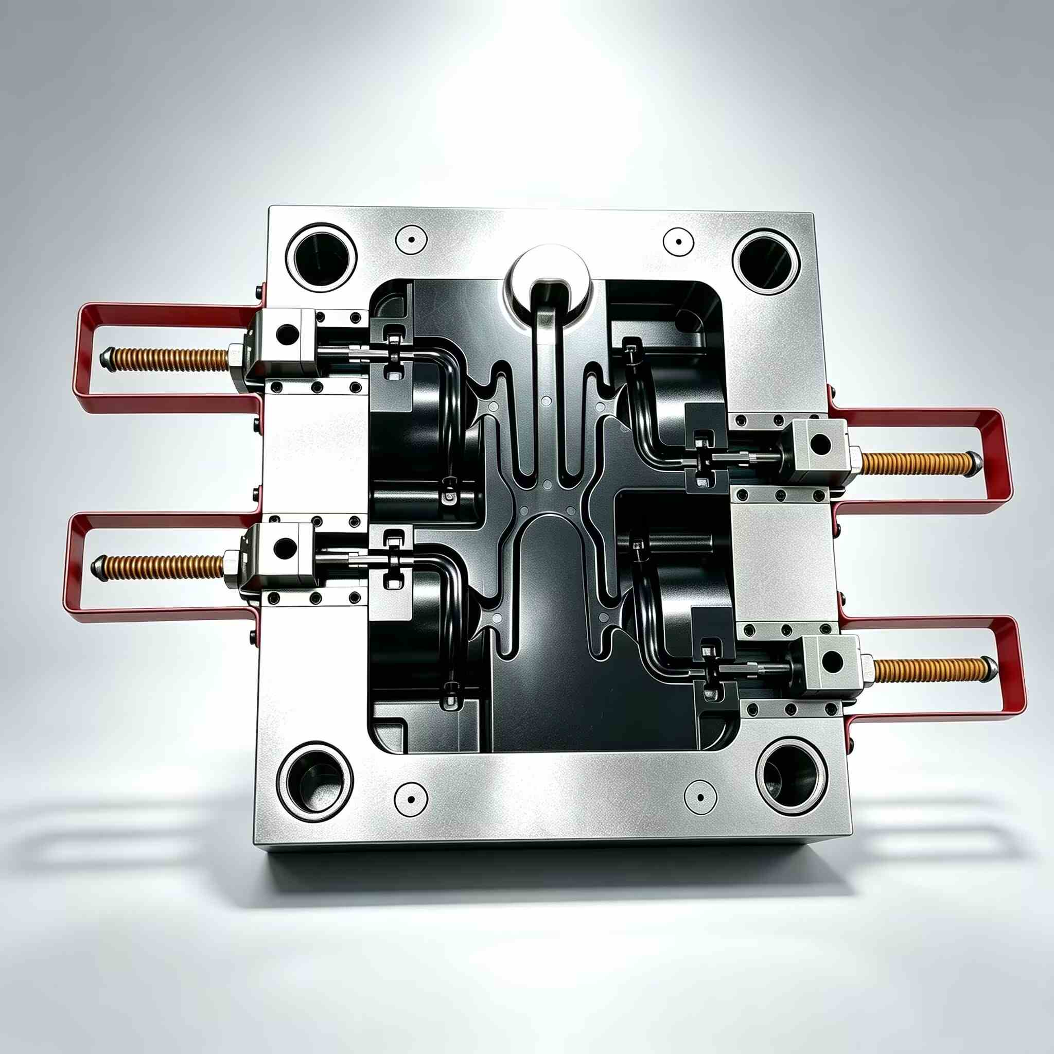
4. Problemi di progettazione dei cancelli
Il cancello è essenzialmente la "gola" del tuo strumento.
Se è troppo stretto o posizionato nel punto sbagliato, la resina non scorrerà nella cavità, ma si incepperà, creando un flusso caotico e instabile. Peggio ancora, i canali di iniezione sottodimensionati agiscono come ugelli ad alta pressione che "maltrattano" il materiale con un eccessivo stress di taglio, lasciando quelle antiestetiche striature che rovinano la finitura superficiale.
Problemi comuni relativi al test Gate
- Cancello troppo piccolo
- Posizione del cancello errata
- Cancello singolo su ampie parti
- Espansione improvvisa del flusso dopo la paratoia
Soluzione
- Se possibile, aumentare le dimensioni del cancello.
- Riposizionare la paratoia per migliorare l'equilibrio del flusso.
- Utilizzare più porte per parti più grandi
- Ottimizza la disposizione dei runner
Una corretta progettazione del punto di iniezione migliora sia la stabilità del riempimento che la qualità estetica.
5. Lo spessore della parete cambia troppo rapidamente
Quando il materiale fuso fluisce da una sezione sottile a un'area più spessa, la velocità di flusso cambia bruscamente. Questa transizione può alterare l'aspetto della superficie e lasciare linee di flusso visibili.
Anche i bruschi cambiamenti di spessore delle pareti aumentano l'irregolarità del raffreddamento.
Soluzione
- Mantenere uno spessore uniforme della parete
- Utilizzare transizioni graduali anziché bruschi aumenti di spessore.
- Aggiungere raggi adeguati alle aree di flusso
Una buona progettazione dei componenti riduce molti difetti di stampaggio ancor prima che inizi la produzione.
6. Scarsa ventilazione all'interno dello stampo
Il gas intrappolato all'interno della cavità può interferire con il flusso del materiale fuso. Quando l'aria viene compressa, il fronte di stampaggio può esitare o cambiare leggermente direzione, lasciando dietro di sé difetti superficiali.
Sebbene i problemi di ventilazione siano più comunemente associati a segni di bruciatura, possono anche contribuire alla formazione di segni di flusso.
Soluzione
- Pulire le prese d'aria ostruite
- Aggiungere ulteriori aperture di ventilazione dove necessario.
- Migliorare la fuoriuscita di gas in prossimità delle aree di fine riempimento
Una ventilazione adeguata favorisce un flusso di materiale più uniforme all'interno della cavità.
7. Problemi di umidità del materiale o della resina
Alcuni tecnopolimeri assorbono rapidamente l'umidità dall'aria. Il materiale umido può causare un comportamento instabile del fuso durante lo stampaggio a iniezione, compromettendo la qualità della superficie.
Rapporti di rimacinazione incoerenti o resina contaminata possono inoltre aumentare i difetti di flusso.
Soluzione
- Asciugare correttamente i materiali igroscopici
- Monitorare i livelli di umidità
- Mantenere la coerenza dei lotti di materiale
- Ridurre il rischio di contaminazione durante la manipolazione
Una qualità stabile del materiale è essenziale per ottenere risultati di stampaggio stabili.
Come risolvere i problemi relativi ai segni di flusso in modo efficiente
Quando compaiono i segni di flusso, evitare di modificare più parametri contemporaneamente. Le regolazioni casuali solitamente rendono più difficile la risoluzione dei problemi.
Un approccio migliore consiste nel verificare il processo passo dopo passo:
- Confermare la temperatura di fusione
- Verificare l'equilibrio della temperatura dello stampo
- Aumentare gradualmente la velocità di iniezione.
- Verificare le condizioni del cancello e del binario.
- Ispezionare le aree di ventilazione
- Revisione del progetto dello spessore della parete
- Valutare le condizioni della resina
Le registrazioni dei processi provenienti da precedenti cicli di produzione stabili possono anche aiutare a identificare più rapidamente le modifiche.
Come prevenire i segni di flusso durante la progettazione dello stampo
Prevenire è sempre più economico che correggere. Molti problemi relativi alle striature di flusso iniziano già durante la progettazione del pezzo o lo sviluppo dello stampo.
Pratiche di progettazione raccomandate
- Utilizzare sistemi di scorrimento bilanciati
- Mantenere uno spessore uniforme della parete
- Evitare una lunghezza eccessiva del flusso
- Progettare posizioni di ventilazione adeguate
- Ottimizzare la posizione del cancello in anticipo
- Durante l'analisi del flusso dello stampo, tenere in considerazione i requisiti estetici.
Quando l'estetica è imprescindibile, bisogna anticipare i problemi. Eseguire una simulazione del flusso di stampaggio nelle fasi iniziali non è solo un lusso, ma è il modo migliore per individuare questi problemi superficiali prima ancora di tagliare l'acciaio.
Credetemi, è sempre più economico ritoccare un progetto su uno schermo che saldare e rilavorare un utensile indurito una volta che è già a terra.
La realtà: non accontentarti di semplici graffi
È facile liquidare un segno di flusso come "solo un problema estetico", ma è un gioco pericoloso. Quei motivi ondulati sono solitamente la prova inconfutabile di un processo fondamentalmente fuori sincrono.
Che si tratti di una discrepanza di temperatura o di un punto di iniezione troppo stretto, lasciare che questi "fantasmi" infestino i vostri pezzi è un modo sicuro per azzerare i margini di profitto con una montagna di scarti.
La verità è che non si può risolvere un problema di superficie semplicemente regolando una manopola a caso sulla pressa. La vera qualità è una questione di tutto o niente: è necessario che la progettazione dello stampo, il bilanciamento del riempimento e il calore lavorino in armonia.
Basta con le supposizioni, individuate la vera causa principale e smettetela una volta per tutte di "spegnere le fiamme".
È così che si ritorna a una produzione stabile e redditizia.


Contattaci