
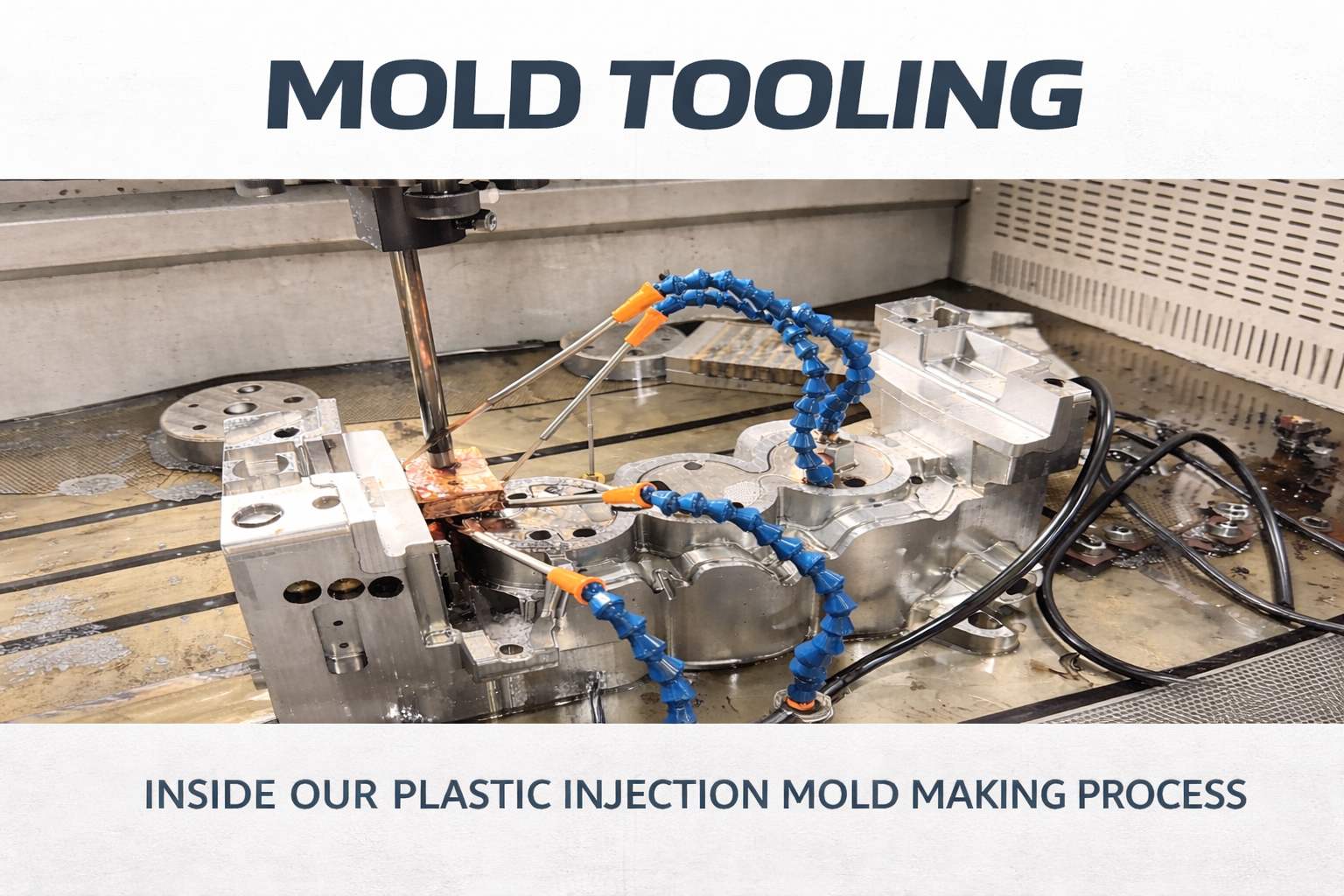
Pourquoi le système d'alimentation directe reste un outil de travail incontournable
-
 auteur
- 4 avril 2026
Pourquoi le système d'alimentation directe reste un outil de travail incontournable
À l'ère des systèmes à canaux chauds complexes et des vannes d'injection, la vanne d'injection directe (ou « grande vanne ») est souvent perçue comme une méthode « traditionnelle ». Mais ne vous laissez pas tromper par sa simplicité : elle reste un incontournable dans tous les ateliers de moulage sérieux, et ce n'est pas sans raison.
Pourquoi il règne toujours en maître dans l'atelier
Le principe fondamental ici est l'efficacité par la simplicité.
Comme le polymère fondu s'écoule directement de la buse dans la cavité, sans passer par un système de canaux, la perte de pression est quasi nulle. Cela fait une énorme différence lors du traitement de résines à haute viscosité comme PC ou PMMA, où la résistance à l'écoulement représente un défi constant.
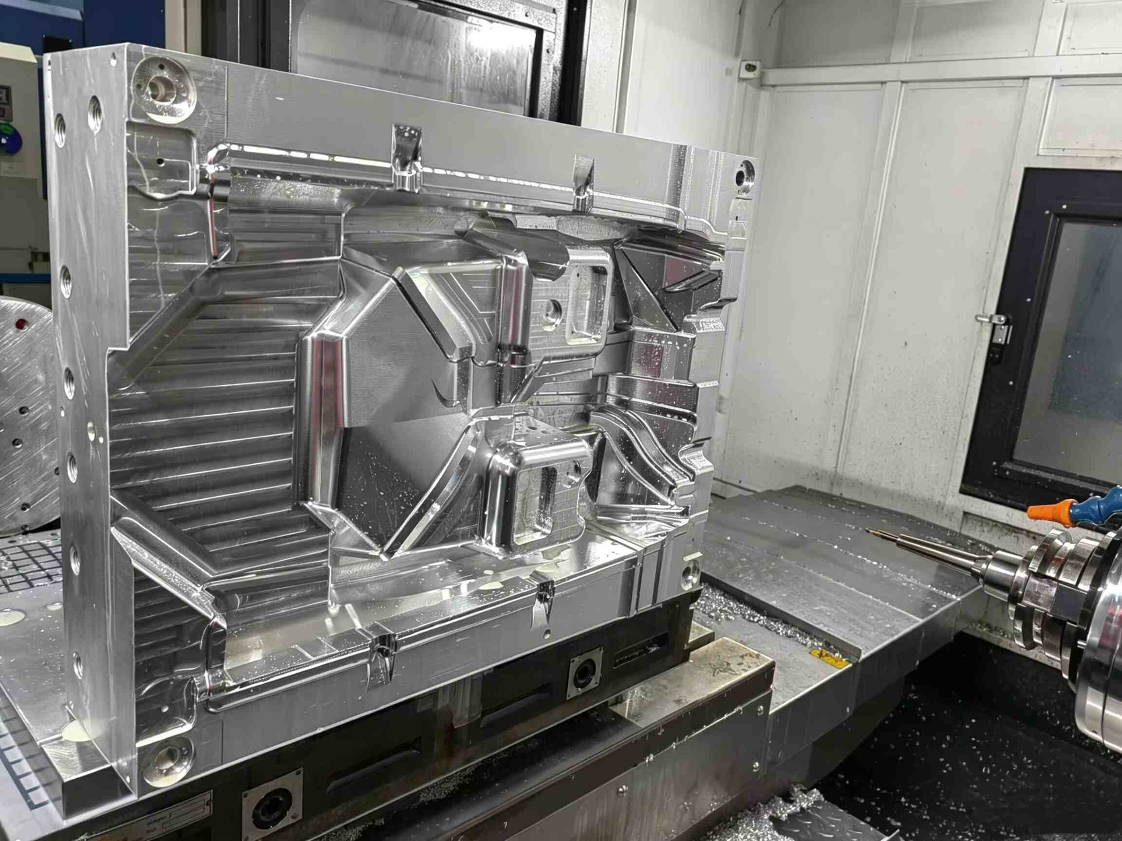
Pour les pièces embouties de grande taille et à forte profondeur — telles que les conteneurs industriels ou les boîtiers robustes —, c'est souvent la solution la plus fiable pour éliminer les problèmes de manque d'emboutissage.
Parce que cela ne nécessite qu'une norme structure de moule à deux plaques, cela contribue également à maintenir :
- coûts d'outillage faibles
- Conception de moule simple
- Production plus prévisible
Le constat de la réalité : cicatrices et stress résiduel
Bien sûr, chaque conception comporte des compromis.
L'inconvénient le plus visible est le cicatrice de porte— un moignon épais et saillant qui nécessite généralement un ébarbage secondaire (découpe manuelle ou par commande numérique). Cela le rend inadapté pour :
- Surfaces très brillantes
- Surfaces cosmétiques « A »
- Composants transparents
Cependant, le problème majeur se cache sous la surface : déséquilibre thermique.
La zone de la grille retient la chaleur beaucoup plus longtemps que le reste de la pièce, ce qui peut facilement entraîner contrainte résiduelle.
Si la configuration du système de refroidissement n'est pas bien optimisée :
- Certaines pièces peuvent se déformer
- Des fissures peuvent apparaître lors du refroidissement après moulage.
Pour les pièces cylindriques ou tubulaires, une attention particulière est nécessaire pour lignes de soudure circulaires. Le centrage par le centre peut introduire des points faibles structurels cachés qui ne deviennent apparents que sous charge.
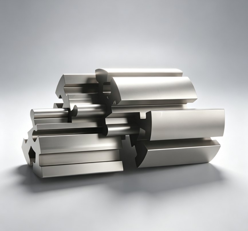
Spécifications techniques : Déterminer les dimensions exactes
En atelier, ces dimensions ne sont jamais devinées ; elles sont calculées en fonction des propriétés des matériaux et des spécifications de la machine.
1. Diamètre de la petite extrémité (d)
Cela doit correspondre au diamètre de la buse de la machine :
d = d_buse + (0,5 ~ 1,0) mm
Plage typique : 2.5 – 4.0 mm
- Trop petit → pression d'injection élevée
- Trop grand → enfilage et coupe difficile
2. Cône de la carotte de coulée (α)
Un tirage correct est essentiel pour le démoulage :
- PP / PE (matériaux à écoulement facile) : 2° – 3°
- PC (matériaux à haute viscosité) : 3° – 6°
Une conicité insuffisante peut entraîner le collage du canal d'injection, augmentant ainsi le temps de cycle et le risque de défauts.
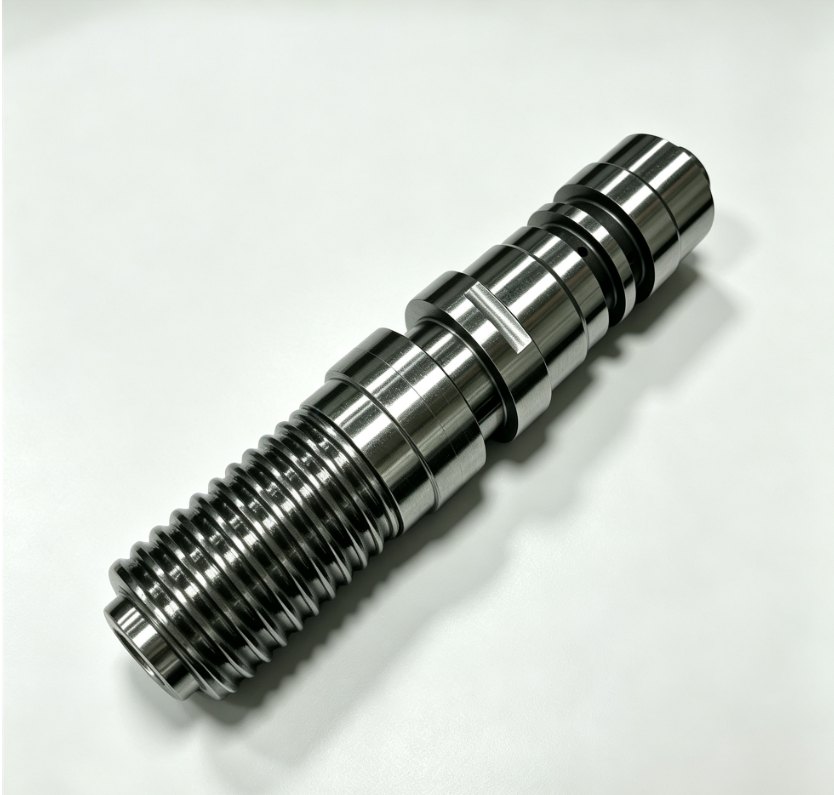
3. Longueur de la carotte (L)
Principe de conception : plus court, mieux c'est
- Recommandé: < 60 mm
Des carottes plus longues entraînent :
- perte de pression accrue
- Plus de matière de limaces froides
- Efficacité réduite du processus
Analyse professionnelle : Le rôle de l'écoulement des moisissures
Lors de l'analyse Mold Flow sur les conceptions à injection directe, l'attention se porte au-delà du simple comportement de remplissage.
Principaux domaines à surveiller :
- Distribution de la température
- Concentration de chaleur près de la porte
- rétrécissement volumétrique
Si une accumulation excessive de chaleur est détectée au centre, des ajustements doivent être apportés :
- disposition des canaux de refroidissement
- Profil de pression d'emballage
Cela contribue à prévenir des défauts tels que marques de retrait et la concentration des contraintes internes.
En résumé
Quand faut-il utiliser un canal d'injection direct ?
Il est idéal pour :
- Pièces à parois épaisses
- Composants industriels
- Applications où l'esthétique n'est pas essentielle
- Volumes de production faibles à moyens
Toutefois, pour les projets nécessitant :
- Automatisation à grande vitesse
- Post-traitement minimal
- finitions cosmétiques haut de gamme
Il est préférable d'envisager des alternatives telles que :
- Sous-portes
- Systèmes à canaux chauds
Dernière réflexion
À [Nom de votre entreprise]Chaque projet est évalué individuellement afin de garantir que la conception de la porte corresponde aux exigences de performance de la pièce, et non pas seulement à ce qui est le plus facile à fabriquer.


Nous contacter